Recent Posts

What are Flowlines in Oil and Gas? Differences between Flowlines and Pipelines

Pipeline engineers must have heard the term “flowlines” frequently. In the oil and gas industry, Flowlines transport fluids between a wellhead and a gathering station like RMS or MSV or treatment facility and vice versa. In a larger well field, multiple flowlines connect individual wells to a manifold. The flow from the manifold is then transferred by a gathering line to a pre-processing stage or to a transportation facility or vessel. Flowlines can run over land or subsea well-field. Flowlines may be buried or at grade on the surface of land or seafloor. The pipelines that collect the flow from multiple flowlines are known as gathering lines.

Flowlines are to a specific well and hence they are located at the well site. It may be a metallic or nonmetallic pipe or a hose. Most flowlines are usually very short. However, they can run for kilometers in onshore applications. Once the flowlines have brought the fluid to manifold or other pieces of process equipment, gathering lines are used. Flowlines are constructed onshore and may be lowered to the seafloor, and have terminal connectors that make an installation at the wellhead easier.

Considerations for Flowline Design

In general, the following guidelines are followed for flowline design:

1. Temperature and Pressure of Flowlines:

The operating temperature for flowlines is usually less. However, the design pressure is very high. The design pressure can range up to 238 bar. The design temperature of flowlines is normally decided based on the environmental conditions as usually process temperature is low (In the range of 60 Deg C).
The design pressure selected must be more than the maximum pressure that can be produced at any instant of the full flowline life cycle.

2. Flowline Design Code:

The normal design code followed for flow lines is ASME B31.4 or ASME B31.8. Click here to find the differences between ASME B31.4 and ASME B31.8.

3. Mechanical Strength:

Depending on the process requirement, flowline sizes vary. The wall thickness of these flowlines is determined using the Barlow formula with a design factor of 0.72. at all locations including road crossings. The Barlow formula assumes a metallic pipe. Carbon steel flowlines are typically installed above ground and this imposes additional bending and thermal (expansion) stresses not taken into account by the Barlow formula. To ensure that code allowable stresses are not exceeded due to these additional stresses on flowlines, support span, expansion loop size & spacing between limit stops, etc should be designed and checked by pipeline stress engineers.

4. Flowline Routing:

For laying new flowlines, designated flowline corridors or streets are followed to minimize land use. For these purposes, flowline town maps showing clearly designated flowline routes are developed for each field, and flowlines are planned to follow these routes only. Opportunities for inspectable bulk lines and headers should always be explored.

In planning flowline routes, inspection/maintenance access must be considered. Flowline crossovers wherever required should be provided. The number of road crossings shall be minimized. Space must be maintained for future flowlines. usually, a minimum clearance of 250 mm is required between adjacent flowlines to allow inspection by an external MFL tool. A marker plate to identify the flowline shall be provided every 200 m and at the crossings (before and after the crossing). Welding is not permitted on the coated flowlines.

For GRP or Composite pipe flowlines, the following requirements should be considered:

  • Route Survey
  • Topographical data
  • Proximity to occupied buildings.
  • Location and classes of Wadis, sand dunes, road crossings, types and density of traffic, etc as applicable.
  • Environmental impact.
  • The manufacturer recommended a bend radius.
  • Flowline length optimization.

5. Flow-line Materials:

In general, a standard line pipe (API 5L) is used as metallic flowline material. The usual grades that contribute to metallic flowline materials are API 5L Grade B. grade X42, X52, and grade X60.

6. Flowline Expansion loops:

Expansion or contraction will occur when the temperature of the flowline material is different from that at the time of installation, or due to pressure and end-cap effects at changes in direction. Suitable expansion loops must be considered while designing flowlines. To prevent preferential expansion in one direction, anchors should be provided to ensure that each expansion loop absorbs only the thrust for which it has been designed.

7. Flowline Hook-ups:

Hook-up refers to the piping required to tie-in the flowline to the wellhead and to production facilities. Hook-up piping is designed to ANSI B31.3.

8. Flowline Installation:

  • All flowlines must be properly supported following the pipe support span to maintain less than 15 mm sagging. For flowlines carrying two-phase flow, it’s better to maintain the sagging below 3 mm. So accordingly the span shall be reduced. Support shall also be provided while crossing existing buried lines.
  • Buried sections of pipelines crossing existing pipelines and other services should be arranged with a ramp or standard road crossing so that access is retained at those services. Where a flowline passes by an electricity pylon, access should be maintained by the use of a ramp or standard road crossing.
  • To absorb expansion stresses at road crossings, it is recommended that carbon steel lines follow the configuration that allows thermal (expansion) stresses to be channeled into the loops on either side of the crossing rather than into the pipe crossing.
  • Use of low radius bends at crossings (except when used in a loop configuration) is not advised as the gooseneck formed interferes with inspection and repair.
  • New flowlines shall be subjected to strength and leak tightness tests after construction. Flowlines are normally hydro-tested at a pressure of 1.25 times the design pressure.
  • GRP flowlines shall always be buried. Special attention should be paid to supporting and anchoring where GRP is installed on supports in on-plot locations.

9. Commissioning of Flowlines:

When the flowline has been successfully hydro-tested, hooked up at both ends, and is ready for operational duty, it is commissioned following specific commissioning procedures.

What is a Pipeline?

A system of pipes and other components used for the transportation of fluids, between plants/facilities. A pipeline extends from pig trap to pig trap (including the pig traps), or, if no pig trap is fitted, to the first off-take isolation valve within the plant boundaries or a more inward valve if so nominated. Pipelines are designed and constructed following ASME B31.4, ASME B31.8, or ISO 14692 codes.

Difference between a Pipeline and Flowline

Both pipelines and flowlines are designed based on ASME B31.4 or B31.8 codes. However, there are some specific differences between a flowline and a pipeline.

  • All flowlines are part of pipelines. However, the pipelines that run in between a wellhead and RMS or MSV, or treatment facility are termed flowlines.
  • In a complete pipeline system, pipe flowlines cover a small part of the pipeline system. Hence, the flow line is a special pipeline with its length limited to the oil field area. On the other hand, pipelines run for kilometers and sometimes cross different countries.
  • Flowlines carry unprocessed crude oil whereas pipelines carry partially processed or fully processed fluids.

What is a Subsea Flowline?

Pipelines that carry fluids in between a subsea wellhead and a surface facility or manifold are called subsea flowlines. They consist of rigid or flexible pipes and in general, carry untreated oil and gas mixtures.

Online Video Courses related to Pipeline Engineering

If you wish to explore more about pipeline engineering, you can opt for the following video courses

What is a Coalescer? Its Types, Working, and Applications

Coalescer is a piece of important industrial equipment for the oil and gas industry used for liquid-liquid or liquid-gas separation from hydrocarbons. A coalescer uses its baffles or electric current to coalesce the small particles or droplets of hydrocarbons into larger ones and then separate them. This is also sometimes known as coalescing filter or filter coalescer. In this article, we will explore more about Coalescers or Coalescing Filters, their types, working, functions, and applications.

What is a Coalescer?

A coalescing filter or coalescer is an industrial device that separates fluid mixtures into individual components. Industrial process fluids contain various impurities like sulfur, ethane, carbon dioxide (CO2), water vapor, methane, etc. To maintain the quality of the final product, these impurities must be removed from the mixture. Coalescer plays an important role in separating these impurities from the mixture using the principle of coalescence.

What does it mean to Coalescence?

The term Coalescence means coming together or agglomerate. In the coalescence process, fluid molecules agglomerate to form a larger whole which is then separated as particulate components. This process is the reverse of the emulsification process.

What is the Function of a Coalescer?

The primary function of a coalescer is to separate mixtures or emulsions into their individual components using various methods. They can separate mixtures from homogenous or heterogeneous mixtures. A coalescing filter can be used independently or as a component of a larger separating unit. Coalescers are widely used as oil-treating equipment.

How does a Coalescer Work?

A coalescer or coalescing filter or filter coalescer consists of several baffle walls or screens located at different points inside the device. The mixture to be separated is then applied to the filter. The baffles of the separation device screen out the components by trapping them in different sections.

The screening mechanism works using the molecular weight and density of individual components. For example, in water-oil separation (liquid-liquid coalescer), the baffle walls present inside the coalescer separate the heavier oil molecules in one direction to a drain point. At the same time, the water vapor molecules diffuse through the filter element to agglomerate which is then drained out of the system gravitationally.

Similarly, in the case of gas-water separation, When the gas stream with water droplets is fed through the coalescer inlet, they diffuse through the filter element, and exit via an outlet port as dehydrated gas. The heavier water molecules coalesce to form larger water molecules and fall to the bottom of the tank for drainage.

Types of Coalescers

Depending on the working mechanism, there are two primary types of coalescers; Electrostatic Coalescers and Mechanical Coalescers.

Electrostatic Coalescers

Electrostatic Coalescers use AC or DC current or both. The water-in-oil emulsion is subjected to a high-voltage electrical field. If a non-conductive liquid (oil in the case of a water-oil mixture) containing a dispersed conductive liquid (water) is subjected to an electrostatic field, the conductive particles combine. There are three physical phenomena that may occur:

  1. The droplets tend to align themselves with the lines of electric force after becoming polarized by the electric current. In such a situation, the positive and negative poles of the droplets may be brought adjacent to each other. The electrical attraction between them brings the droplets together and causes them to agglomerate.
  2. Due to an induced charge, the droplets may be attracted to an electrode. Due to inertia in an AC field, small water droplets vibrate over a larger distance promoting coalescence. In a DC field, the droplets tend to collect on the electrodes, forming larger and larger drops and finally they fall by gravitational force.
  3. The film of the emulsifier surrounding the water droplets gets distorted and weakened by the electric field. When subjected to an alternating current field, the water droplets dispersed in oil will be elongated along the force lines during the first half cycle. During the low-voltage portion, when they are relaxed, the surface tension will pull the droplets back toward the spherical shape. In the next half of the alternating cycle, a similar effect is obtained. The weakened film is thus more easily broken when droplets collide, making coalescence more likely.

Using any one of the mechanisms, the electric field forces the droplets to move about rapidly in random directions, which in turn greatly increases the collision potential with another droplet to cause coalescence.

An AC current in the 50 – 60 Hz range is usually used for this purpose. Electrostatic coalescers find extensive applications for separating water-fuel emulsions in offshore oil and gas production facilities.

Mechanical Coalescers

As mentioned earlier, mechanical coalescers work by employing a series of filter elements or barriers for separation. In a mechanical coalescer, the water droplets are intercepted by the barriers. On the other hand, the oil gets thinned by the baffle fibers while passed through them. In the process, the water separates out from the oil. A plate coalescer is a typical example of a mechanical coalescer.

Plate Coalescers:

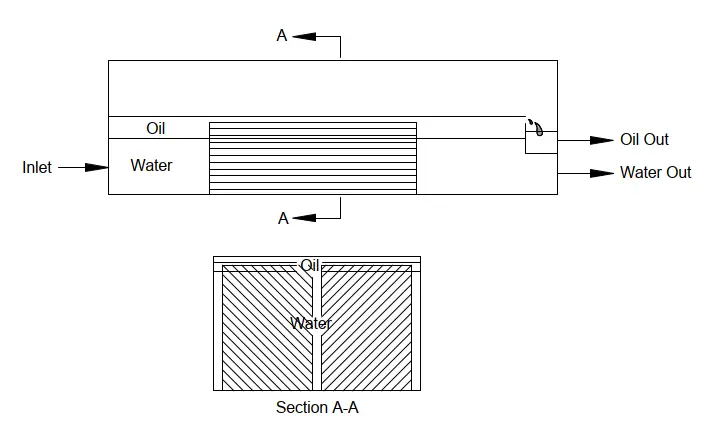
Plate coalescers are available in various configurations. These are commonly known as parallel plate interceptors (PPI), cross-flow separators, or corrugated plate interceptors (CPI). The working principle of all plate coalescers depends on gravity separation to allow the oil droplets to rise to a plate surface where coalescence and capture occur.

As shown in Fig. 1, flow is split by a number of parallel plates spaced 0.5–2 inches apart. The plates are sometimes inclined horizontally. It promotes oil droplet coalescence into films which guide the oil to the top for entrapment into channels, thereby preventing remixing with the water. The plates provide a surface for the oil droplets to collect and for solid particles to settle.

Schematic of a plate type Coalescer
Fig. 1: Schematic of a plate-type Coalescer

Plate separators are recommended when:

  • There is a steady water flow rate.
  • Size and weight are not constraints.
  • Solid contaminants are not significant in the waste stream, and sand content is less than 110 ppm.
  • To periodically clean the plate packs, Utilities and equipment are available.
  • Influent oil content is high and oil concentration must be reduced to 150 mg/l for effective second-stage treatment in a downstream unit.

Plate separators are not recommended when:

  • Size and weight are the primary considerations.
  • Influent droplet sizes are below 30 mm.
  • Sand particle diameters are less than 25 mm, and solids removal is a primary objective.

Depending on which product the coalescer separates out, coalescing filters are categorized into various types like:

  • gas coalescer
  • oil coalescer
  • natural gas coalescer filter
  • fuel coalescer
  • condensate fileter coalescer, etc

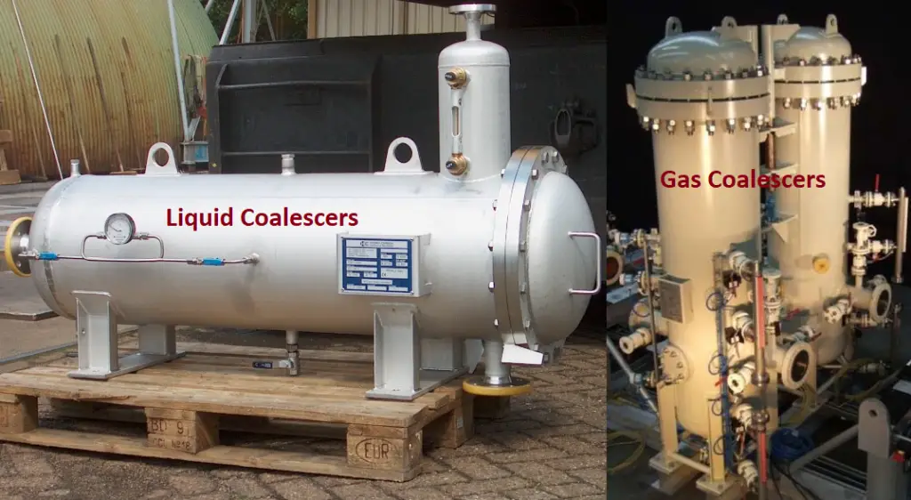
Fig. 2 below shows a typical example of liquid and gas coalescers used in the oil and gas industry.

Typical Example of liquid and gas coalescers
Fig. 2: Typical Example of liquid and gas coalescers

Applications of Coalescers

Coalescers or Coalescing filter separators are employed for a wide range of applications in the downstream oil and gas, petrochemical, and chemical industries for liquid-liquid or liquid-gas separation.

Downstream Operations: In downstream oil and gas, coalescers find applications for refining the products. At natural gas refineries, coalescing filters are used to de-humify natural gas to ensure product quality and purity. Also, in a gas-oil coalescer system, coalescers purify the natural gas by eliminating condensate and several natural liquids.

Again, coalescers have the capability to prevent the corrosion of compressors, amine/glycol absorbers, turbines, and membrane filtration systems by removing corrosive contaminants like sulfur, water vapor, etc.

For recovering lube oil from a compressor, Coalescing filters are installed at the compressor inlet. Fluids that are fed into the compressor inlet usually have a particulate matter, aerosols, dissolved hydrocarbon liquids, and slugs. To improve compressor performance and recover the oil these are extracted using a coalescer placed upstream of the compressor.

Petrochemical Industries: For phase removal of water vapor, amine solutions, and sulfur from petrochemical feedstock prior to storage, Liquid-liquid coalescers can be used.

Coalescer Design

A coalescer has a vertical or horizontal configuration. The parameters that affect the design of a coalescer are process requirements, safety, and economics. The following parameters must be decided prior to coalescer design:

  1. The minimum, average, and peak flow rates of Gas and liquids.
  2. Operating and designing temperatures and pressures.
  3. Feed stream surging or slugging tendencies.
  4. Density, viscosity, and compressibility of the fluids.
  5. The required degree of separation

What is the difference between a Filter and a Coalescer?

The main difference between a filter and a coalescer is that a filter normally separates a solid particle from gas or liquid whereas a coalescer provides the separation of two phases.

What is an Oil Coalescer?

An oil coalescer is a filtration system that removes gasoline, diesel, non-emulsified oil, and fuels from a waste stream. Closely spaced oil-attracting media is used in the oil coalescers to promote agglomeration of larger oil particles, which then flow up the surface.

Introduction to Reboiler Control

Reboiler Control is very effective to a distillation column as it prevents the distillation column from disturbances occurring in the heating medium. Reboiler controls include reboiler temperature control, reboiler level control, reboiler duty control, reboiler steam flow control, etc.

The most suitable variable for regulating a column is boil-up. Boil-Up is controlled to achieve the desired product quality normally in the bottom section.

When the boil-up rate is kept constant, the reboiler control valve is usually manipulated by a heating medium flow controller. When the boil-up is regulated to achieve desired product purity, the reboiler control valve is directly or indirectly manipulated by a tray temperature, a product analyzer, or the base level. Indirect manipulation is performed by a cascade controller that varies the set point of the heating medium flow controller. The flow controller, in turn, manipulates the reboiler control valve.

Reboiling with a Condensing Fluid

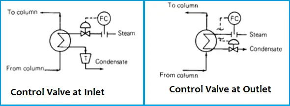
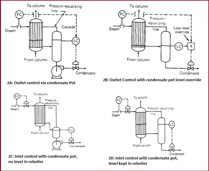
Example of this type of reboiler is steam reboiler and refrigeration reboilers. The control valve may be located either at the inlet line or at the condensate outlet line as shown in Fig. 1.

Fig. 1: Position of Control Valve at Reboiler System

When the control valve is located at the inlet of the reboiler, the heat transfer rate is controlled by changing the reboiler condensing pressure & therefore condensing temperature. When a higher boil-up is needed the valve opens and increases the reboiler pressure which increases the reboiler temperature difference, which in turn increases the boil-up rate.

When the condensate flow rate is manipulated, vapor always condenses essentially at the supply header pressure. Heat transfer rate is changed by partially flooding the reboiler with condensate & thereby varying the surface area available in the reboiler for condensation.

Location of Control Valve (Upstream Vs Downstream of reboiler)

The location of the control valve has a major impact on the efficiency, performance of the whole column. There are several pros and cons for each location which are as follows,

1. Controlling the inlet valve immediately changes the vapor flow which in turn changes reboiler pressure & the heat transfer rate. On the other hand condensate outlet valve has no direct influence on vapor flow rate. Condensate flow determines the condensate level & this level changes slowly. Because of this slow response, manipulation of reboiler vapor flow is a far better means of control than condensate flow control.

2. The condensate outlet control scheme, sometimes the control valve in the condensate line can’t handle the amount of condensate the reboiler can generate, a maximum vapor flow may be reached with condensate still covering a portion of tubes and the pressure difference between the reboiler and the condensate system is small a condensate pot with pump may be needed to overcome the problem.

The converse of this problem can also be troublesome when the reboiler is unable to condense vapor as fast as the condensate valve removes the liquid, the liquid seal in the reboiler may be lost & vapor will pass into the condensate system which results in a dramatic loss of heat transfer also causes hammering in the condensate system. This problem can be overcome by the above control scheme (Fig. 2-A) without a pump. The other best arrangement is as shown in Fig. 2-B

Condensate pots in Reboiler
Fig. 2: Condensate pots in Reboiler

Here the flow controller (Fig. 2B) normally controls the condensate valve, with the level override cutting in whenever the level falls too low.

3. The condensate outlet scheme permits reboiler operation at a higher pressure because it eliminates the pressure drop at the inlet control valve. It is a major advantage when refrigerant vapor is the heating medium. As refrigeration compressor interstage pressures are often set to  “ride’’ on the reboiler condensing pressure. The higher the pressure the lower the refrigerant compressor power consumption.

4. In a steam-heated reboiler, the vapor inlet control scheme minimizes the reboiler tube wall temperature. This reduces reboiler fouling (process side) and lowers thermal stresses at the reboiler heads.

If fouling becomes a serious concern, it is often desirable to keep the reboiler wall temperature as low as possible. The arrangement in Fig. 2C fully utilizes the reboiler area to automatically minimize the condensation temperature.

5. A smaller control valve is required with the condensate outlet scheme.

6. The vapor inlet scheme may be troublesome when the excess surface area is available at the reboiler. During initial operation, the inlet control valve closes to reduce condensing temperature (Q=UA ΔTlm) UA is large, where Q is heat duty, U is overall heat transfer coefficient, A is reboiler area, ΔTlm is log mean temperature difference) & condensing pressure. If condensing pressure falls below condensate header pressure(e.g. with steam reboiler using 15 to 35-PSIG steam), it will be impossible to remove the condensate. The condensate that is not removed will be built up into the reboiler and floods some of the tube surfaces. The point at which condensate will start building up can be calculated. With condensate tubes partially flooded any further variations in steam flow to the reboiler will affect both the delta T in the reboiler and the fraction of tube surface until a new equilibrium is reached. These two often interact, giving rise to slow, sometimes erratic responses. The steam trap will offer a little assistance with control of the condensate level. Further, if the reboiler load changes are sudden, the above-manipulated equilibrium will be difficult to establish or sustain as well as the hunting of the control valve happens.

To overcome this problem a submerged condensate pot is often installed instead of the stream trap as described earlier. An alternative remedy is replacing the steam trap with a level condensate pot (refer to Fig. 2D). By varying the level control set point the surface in the reboiler can be adjusted so that the reboiler operates at a pressure high enough to ensure condensate removal at all times without a pump.

Note: The bottom of this drum is located below the bottom of the condensing side of the reboiler otherwise, “dry’’ reboiler operation at high rates will not be possible and reboiler capacity will be reduced.

7. Steam traps are considered generally troublesome because they are prone to plug or stick open. The use of a steam trap is considered a disadvantage. The vapor inlet scheme in Fig-6 can overcome this problem.

8. In the vapor control scheme, during the reboiler turn down flow rate across the valve changes from non-critical to critical. As the boil-up falls, so does the absolute pressure downstream of the valve. When the ratio of u/s & d/s pressure exceeds a critical value, critical flow is established through the valve.

To prevent this problem, it’s best to design the system to operate over its normal range in one flow or another. A level condensate seal pot can keep up the d/s pressure during turn-down conditions. Alternatively installing a pressure regulator u/s of the flow controller can lower the pressure u/s of the inlet valve.

Various Reboiler Controls
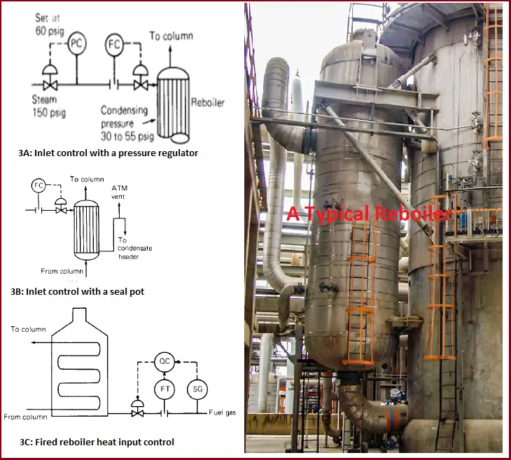
Fig. 3: Various Reboiler Controls

9. With the condensate outlet scheme (Fig. 3A), condensate accumulation in horizontal shells at turned-down conditions can flood most of the exchanger baffle windows and restrict vapor passage through the window. This may result in liquid hammering.

Based on the above points it has been observed that the vapor inlet scheme is more effective in reducing disturbances in the steam supply than the condensate outlet scheme.

10. The condensate outlet scheme can destabilize thermosiphon reboiler operation.

11. Corrosion due to the condensate level maintained in the reboiler often occurs with the condensate outlet scheme. The layer of rust on the steam side of the reboiler clearly indicated the level at which the condensate ran.

Loop Seal

In some low-pressure steam reboiler, the condensate pot is replaced by a loop seal (see below figure). Increasing the steam flow rate to the reboiler raises the pressure in the shell of the reboiler, which in turn lowers the liquid level in the reboiler & exposes more tube area. The behaviors of this system are similar to that of the condensate outlet scheme. The height of the liquid in the loop is typically 5 to 10 ft. This arrangement (Fig. 3B) can be troublesome when the reboiler heat load or the steam mains pressure tends to fluctuate, and it is usually best to avoid it.

Reboiling with Sensible Heat:

Sometimes hot oil or hot gas is used for reboiling purposes. Heat input is regulated by changing the heating medium flow through the reboiler, which in turn varies both the heat transfer coefficient and the temperature difference across the reboiler. The reboiler responses depend on whether the heat transfer coefficient variation or variation is a dominant factor affecting heat input. Generally, at high reboiler ΔT, the heat transfer coefficient effect dominates while the ΔT effect becomes more dominant at low reboiler ΔT.

Direct-fired reboiler:

This type of reboiler (Fig. 3C) is basically used in refineries. Usually, these are fires with a mixture of gases vented from various units supplemented by natural gas. The problem that frequently happens with direct-fired reboiler is heat input changes with fuel gas composition. For this reason, it may be difficult to control the fuel flow rate to the furnace, and heat input control may be necessary.

Correction for composition can be done using a factor (heating value √S.G), known as Wobbe Index, where SG is the gas-specific gravity. For hydrocarbon mixture, the Wobbe Index varies linearly with SG, and measurement of SG is sufficient for composition correction. The below arrangement shows the control system using Wobbe Index.

The density meter should be installed directly in the fuel gas line, downstream of the knock-out drum, and any points where fuel gas streams are added and where it would be unaffected by vibrations.

Introduction to Clean Energy Piping & Pipeline Systems

The energy consumption of the world is increasing day by day. As per the energy requirements for the future, the energy production required will be in big capacity. The high-capacity energy production like Three Gorges, Jebel Ali, and Kashiwazaki-Kariwa will be producing more than 10,000 MW. However, as fossil fuel is non-renewable and is being consumed at a higher rate than produced, it will end up in the next 46 years. At the same time, fossil fuels create a huge level of pollution in the environment. To control pollution and meet the future energy demand the only option is renewable clean energy.

Clean energy is a form of energy that originates from zero-emission renewable sources. When consumed, clean energy does not pollute the atmosphere. Clean energy produces power and energy without producing negative impacts on the environment.

As per the RE100 initiative, where hundreds of big companies have already announced their commitment to get 100% of their power from renewable sources, the energy that emits little to no greenhouse gas emissions and includes renewable and carbon-free sources is more adaptable along with the high requirements. Piping systems of these energy sources are sometimes challenging due to the geographic and energy characteristics, including resources like

  • Geothermal Power
  • Biomass Power
  • Hydropower 
  • Nuclear Energy
  • Hydrogen Energy
  • Solar Power

Geothermal Energy

Indonesia is estimated to have about 28 GW of geothermal potential for power generation, located on the Ring of Fire, and is home to more than 200 volcanoes which account for 40 percent of the geothermal potential of the entire world. 41 volcanoes are present over the island, making it a highly active seismic zone, providing abundant geothermal resources. Thus holds the highest potential for energy production. Wayang Windu is the world’s largest flash steam power plant.

Wayang Windu has 227 MW of total installed capacity, due to the high power generation and the geographical features of the land over there often experiences high thermal expansion & contraction, shifts in the ground, changes in elevation, uneven terrain, and also the need to disassemble and relocate the piping system, making construction or expansion of plants, wells and the piping systems that connect them often presenting several challenges and resulted in a complex piping scenario. In permanent welding, the rigid joints would not be able to provide the flexibility to accommodate thermal and seismic movement. To alleviate these problems, grooved mechanical piping was specified, installation of the flexible couplings was less time-consuming than welding and flanged joint, and they provided a small amount of angular and linear movement, meeting the requirements for flexibility and maintainability and offering additional benefits onsite.

Biomass Plants

Ironbridge power plant which is located at the Severn Gorge, UK, is the world’s biggest biomass power plant. As fuels materials like wood chips and palm kernel shells, which offer a more stable alternative. Wood chips will get transported inside the pipelines as water slurries employing this loss on lower heating value would preclude the usage of water slurry pipelines for direct combustions, this biomass delivered through pipelines is suitable for processes that do not produce contained water as vapor (eg. supercritical water gasification).

Renewable natural gases (RNG) and renewable hydrocarbon fuels formed from existing waste streams and renewable and sustainable biomass sources like animal waste, crop residuals, and food waste by various processes such as hydrotreating, pyrolysis, gasification, and other thermochemical and biochemical technologies, 

The same chips transported in a heavy gas oil take up as much as 50% oil by weight and result in a fuel that is >30% oil on a mass basis and is about two-thirds oil on a thermal basis. 

 Production of bends with flow-optimized radii can minimize the pressure loss & reducing the number of welds can increase benefits, RNG makes an important energy tool. 

Hydropower

The traditional renewable energy resource is famous due to the geographic features of India and is in use in over 160 countries. In hydroelectric power plant (HPP)projects usually, it will be steeply inclined with rough terrain conditions. To adjust to these conditions grp pipes are used more as they are lighter, thus it will be easier for the transportation and installation of these materials. Operations carried out at high-altitude areas may bring about lower temperatures. 

Conventional hydropower generation is highly cost-effective and not feasible in certain areas. Times changed, and steps have developed for making use of hydropower more effectively. Lucid Energy came out with an idea to make it possible by fixing a small turbine in the existing water pipeline doing the trick. They are designed along gravity-fed, pressurized transmission and distribution lines, effluent outfalls, and other pipe conveyance systems. These micro-hydro systems can be positioned in municipal water, wastewater, industrial water, and irrigation systems.

 They can operate across a wide range of head and flow conditions inside most common piping materials such as steel, ductile iron, concrete, or any material that can be mated with steel pipe thus they can provide clean and baseload energy, without interference of wind and solar and environmental repercussion. Since most of the piping runs underground.

Nuclear Energy

Other than Hydropower; nuclear energy is by far one of the highest sources of energy production. Even though nuclear energy is renewable, the fuel that is required is not renewable, Nuclear power plants over the world that can produce 1 GW of energy are considered to be the most reliable source of energy. The conditions under which the fission takes place are extremely hostile, and most of them are situated on the coast and use seawater for cooling which calls for special piping resistant to the high corrosiveness of saltwater. means the finest stainless-steel pipes and tubing are required so that they can deal with high temperatures and pressure along with corrosiveness nickel alloys are also been used in the nuclear industry widely as it a widely adaptable element and have a great range of properties such as heat and corrosive resistant.

 Apart from that next-generation nuclear power is also a widely discussed topic Concepts so far include nuclear reactors dozens or even hundreds of times smaller and more distributed. also trying to develop offshore nuclear reactors, like the floating platforms the oil and gas industry already uses. They should be able to withstand Category 5 hurricanes. 

In the case of power loss during an emergency, the supply of cold seawater would always be available to cool the reactor core as the reactor core submerged beneath the platform.

High pressure piping in nuclear power plants
Fig. 1: High-pressure piping in nuclear power plants

Hydrogen Energy

Over the past years, the utilization, research, and demonstration of hydrogen energy has risen and are already widely used in some industries, as for as now so many types of research are ongoing to reduce the barriers present now and also to reduce the costs considering its potential to support clean energy transitions, currently natural gas is considered to be the primary source of hydrogen production. They can also be extracted from fossil fuels and biomass, from water, or a mix of both. 

On the other hand, Green hydrogen(H2) is obtained by steam reforming or else by splitting water by electrolysis. The physical and chemical properties of hydrogen are different from those of natural gas, so it is not possible to exchange natural gas for hydrogen in the existing natural gas pipe system. The durability of the existing pipelines is still one of the limiting factors.

As we know hydrogen is highly inflammable and dangerous to compress, and it can also alter traditional steel pipes and welds. Improperly designed pipes, valves, and fittings of these piping systems can cause small leaks and cracks which can lead to the failure of the pressurized gas.

For designing the hydrogen pipeline and piping systems, the ASME B31.12 piping code has been published. Typically carbon steel and sometimes alloys are used in production plants.

Hydrogen Power Plant
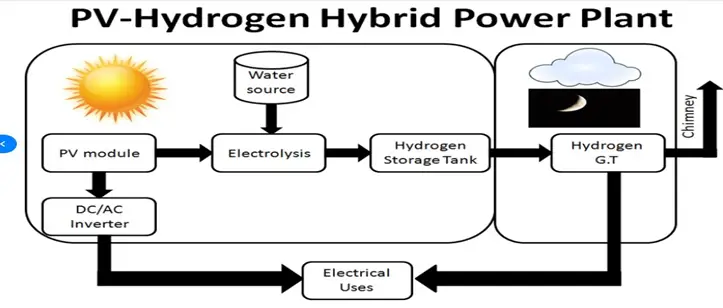
Fig. 2: Schematic of Hydrogen Power Plant

For delivering large volumes of hydrogen, existing pipelines are used as the economical option. some of the technical concerns of the pipeline transmission are,

  • hydrogen has the potential to embrittle the steel and welds used to fabricate the pipelines
  • controlling hydrogen permeation and leaks
  • requirement for lower cost, hydrogen compression technology which is more reliable, and more durable.

Using FRP pipelines for hydrogen distribution is a potential solution, also the installation charges for these pipelines are more than 20% less than steel pipelines as they are obtained in sections that are much longer minimizing the welding requirements.

What is a Flare KOD | Working, Functions, Sizing, and Design of a Knock Out Drum

A Knock out drum is a specific type of pressure vessel in the flare header system used to remove & accumulate any condensed & entrained liquids or liquid droplets from the relief/flare gases. This process equipment is also known as the flash drum, knockout pot, KO drum, knock-out vessel, or flare KO drum. A knock-out drum is one of the primary components in a pressure-relief arrangement system in process industries. Flare knockout drums are available in vertical or horizontal configurations.

Knockout drums are classified as “two-phase” when they separate gas from the total liquid stream. Again, they are known as “three-phase” when they separate gas, water, and oil phase means separating crude oil and water from the liquid stream.

Function of a Knockout Drum

The main function of a knockout drum is to provide residence time for liquid discharges and to limit the size of droplets directed to the liquid seal drum or the flare burner. They are used to remove any liquid droplets of oil or water from the industry-relieved/flare gases. The liquid in the vent system is not desirable due to the following reasons:

  • the liquid causes irregular combustion and smoking.
  • the liquid can extinguish the flame.
  • liquid flaring can generate a burning chemical spray that could reach ground level and cause a safety hazard.

It is therefore the main function of a knock-out drum to remove the liquid that may be condensed out in the transfer lines and collection headers. Also, as the liquid product is recovered from the relieving gas, the efficiency of product recovery increases.

Flare KO Drum Design Configurations

A flare drum is designed in either a horizontal or vertical configuration. The KO drum configuration is decided by operating parameters and space availability. When a large liquid storage capacity is required and vapor flow is high, a horizontal flare KO drum is preferred. Horizontal knockout drums have a low-pressure drop. They are economical and can handle large relief loads. In general, three types of horizontal KOD configurations are found. They are

  • Horizontal drum with the vapor entering at one end of the vessel and exiting at the top of the opposite end without internal baffling.
  • Horizontal drum with the vapor entering at each end on the horizontal axis and a central outlet.
  • Horizontal drum with the vapor entering in the center and exiting at each end on the horizontal axis.

Vertical knockout drums are only used when the liquid load is low and there is a scarcity of plot space. Vertical flash drums are well suited for incorporating into the base of the flare stack. Basic vertical KOD configurations are:

  • Vertical KO drum with radial inlet nozzle and top outlet nozzle.
  • Vertical vessel with a tangential nozzle.

Sometimes, a combination of a vertical drum in the base of the flare stack and a horizontal drum upstream to remove the bulk of the liquid entrained in the vapor is also found in process plants.

Designing and Sizing of Flare Knockout Drum

The sizing of flare KOD is basically a trial-and-error method with widespread table lookups. The sizing process is constrained by a set of fluid dynamic and mechanical relationships and is based on the gravity-settling theory. The principle of settling theory is that the liquid droplets will settle due to gravitational force. The size of the knock-out vessel is decided by the anticipated liquid and vapor flow. The KOD diameter is estimated using the maximum allowable vapor velocity.

The knockout drums are designed and sized following a specific length-to-diameter ratio in the range of 2 to 4. This maintains a low vapor velocity such that the liquids settle out. The KO drum design requires the expert application of many thumb rules. Because of multivariable manual trial-and-error procedures, the knockout drum design is usually done by experienced process engineers.

A liquid level indicator is always installed as these knockout vessels shall remain drained and free of excess liquid.

The KO drum sizing is done following the bellow-mentioned two steps as per API 521:

Step-1: The starting step of Flare knock-out drum sizing is to determine the drum size required for liquid entrainment separation. Liquid particles separate: If the residence time of the vapor or gas is equal to or greater than the time required to travel the available vertical height at the dropout velocity of the liquid particles, and if the gas velocity is sufficiently low to permit the liquid dropout to fall.

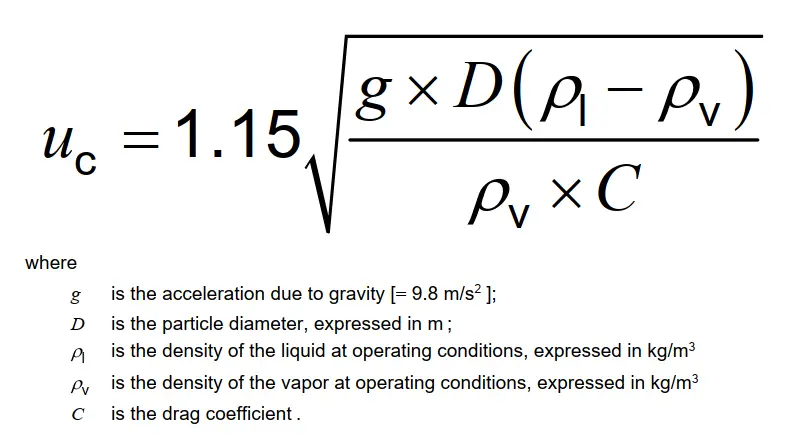
This vertical height is considered from the maximum liquid level. To prevent large slugs of liquid from entering the flare, the vertical velocity of the vapor and gas should be low enough. The dropout velocity (uc), in m/s, of a particle in a stream, is estimated using the following equation:

Equation for drop out velocity
Fig. 1: Equation for drop out velocity

Step-2: The next step in sizing a flare knockout drum is to take care of the effect that any liquid present in the drum can produce on reducing the volume available for vapor/liquid disengagement. This liquid may result from:

  • condensate that separates during a vapor release, or
  • liquid streams that accompany a vapor release.

The capacity of the liquid holdup of a flare KO drum is decided based on the consideration of the amount of liquid that can be released during an emergency situation without exceeding the maximum level for the intended degree of liquid disengagement. Different applications require different holdup times. However, the primary requirement is to provide sufficient volume for a 20 min to 30 min emergency release. When it takes longer to stop the flow, longer holdup times may be required.

Locating the Knockout Drum

Flare knockout drums should be located considering the following:

  • liquid droplet agglomeration and vapor condensation when there is a long line between the flare stack and the flare knockout drum.
  • knockout drum maintenance access during normal and emergency situations.
  • thermal radiation effects on flare knockout drum instrumentation and necessity for thermal shielding.

In general, knockout drums are located on the main flare line upstream of the flare stack or any liquid seal. However, if any equipment releases a large amount of liquid to the flare header, additional KO vessels inside the battery limit are installed to collect these liquids. This not only reduces the sizing load of the main flare KOD but also increases product recovery. Knockout drums are also installed ahead of compressor suction to eliminate liquid from entering the compressor.

Maintenance Requirement of Knockout Drums

Knockout drums are considered as dirty service and routine maintenance cleaning of the gauge glasses, checking level instruments, pump shut down instruments, etc must be planned as per vendor recommendations.

What are the types of Knock-out Drums?

Depending on configurations there are two types of knockout drums; vertical and horizontal knockout drums. Again, based on separation capability they are classified as; two-phase knock-out drums and three-phase knockout drums.

What is the burning rain phenomenon?

when a liquid hydrocarbon droplet does not burn completely within the flare flame envelope and the rate of burning is lower than the rate of settling of the liquid droplet, a phenomenon known as burning rain occurs. When burning rain occurs, slugs of liquid are carried over from the flare knockout drum, liquid seal drum, or re-entrainment of liquid accumulated within the flare piping or the flare gas riser.

What is the difference between a Knockout Drum and a Separator?

Knockout drum and separator are used interchangeably. The basic function of both knockout drums and separators are the same. However, from the application point of view, there is a slight difference. Knock-out drums are used in the flare systems or just before compressors for safety concerns and product recovery. Separators have broad applications. They are extensively used in processing plants to separate oil, water, and gas streams for sending for further processing.

What is a Basis of Design or BOD? How to Write a Basis of Design for a Project?

The Basis of Design (BOD) is a very important document for every project. The basis of design or project design basis provides all the principles, business expectations, criteria, considerations, rationale, special requirements, and assumptions used for decisions and calculations required during the design stage. So, a basis of design is a project baseline and overview to kickstart the project activities.

The BOD is prepared by the Engineer or Designer with inputs from all departments. For oil and gas projects, the basis of design is usually prepared by process engineers. In this article, we will explore more about the Basis of Design, its purposes, writing methodology, responsibilities, etc.

What is a Basis of Design Document?

The Basis of Design document describes the technical approach planned for the project. Preliminary project technical details are incorporated in this essential document. The BOD is prepared during the pre-design stage and it serves as the basis for all the design calculations and other design decisions. Note that, BOD is not a substitute for code and standard guidelines or project design drawings. But a BOD simply includes the list of individual items to support the design work process based on the owner’s project requirements.

Even though the basis of design starts at the pre-design phase, the document is dynamic in nature. As the design work progresses, the basis of the design document is updated to include a specific description of the system and components, its function, how it relates to other systems, sequences of operation, and operating control parameters. However, BOD does not include detailed project information or calculations.

Purpose of Basis of Design Document

The basis of design for any project serves several important purposes like

  • It documents the major process and assumptions behind specific decisions.
  • A BOD concisely captures the owner’s requirements and vision into technical terms and design parameters.
  • For the commissioning team, BOD is a very important document to evaluate the ability of a design.
  • The BOD provides a listing of all major design decisions.
  • This is the document that provides a technical document providing the thought process of design professionals for developing the plant.
  • A project basis of design helps in calculating the life cycle cost analysis.

Responsibilities of the Basis of Design Document

As already stated earlier that the designers and engineers are responsible for creating and managing this document. They ensure that the document is complete in all respect. However, the client and commissioning manager review the document and approve it. Creating a quality Basis of Design for the project’s success by improving the communication and collaboration between the design consultant and client.

How to Write a Basis of Design (BOD)?

Writing a basis of design specification starts with the owner’s project requirement document. A lot of required data will be obtained from that document to start writing the BOD. In the following section, I will list the important parameters that are usually added to the basis of design for oil and gas projects. This will serve as a typical basis for design engineering examples.

Contents of a Basis of Design Oil and Gas Project:

Oil and gas projects typically include the following information on the basis of design documents.

  • Project background: This section includes a briefing of the project.
  • Document purpose: This section lists the requirement of this document.
  • Project Interface
  • Project Scope: This section includes the overall scope of the project in detail. A Separate scope of each discipline involved in that project is briefed. For example, a typical oil and gas basis of a design document may include the scopes or process team, piping team, pipeline teal, civil team, control and automation team, electrical team, etc.
  • Design basis: This section lists all the design information or assumptions for each discipline. Separate sub-modules of individual disciplines are prepared as process design basis, piping design basis, pipeline design basis, civil design basis, electrical design basis, C&A design basis, etc.
  • Design Philosophy: In this section, the following sub-modules (as applicable in that specific project) are included.
    • Operating, Control & Safeguarding Philosophy
    • Sparing & Maintenance Philosophy
    • Metering Philosophy
    • Sampling Philosophy
    • Design Philosophy Based on H2S content
  • Technical Assurance Review: This section ensures the safety and quality of the project by performing various quality reviews like Design review, HAZOP study, SIF, Alarm rationalization review, etc.
  • Design Criteria: In this section of the project design basis, various calculation basis is provided. For example,
  • Codes and Standards: In this section of the basis of the design document, all the relevant codes and standards are listed along with their editions.
  • Government Laws and regulations, if applicable
  • Process specification of Technology provider, if applicable
  • References and Appendices: This is the final section of the design basis. Here, all the references and appendices are attached to substantiate the above-mentioned decisions.

The above-mentioned points are the minimum required information to be produced in any basis of design document for oil and gas projects. The complete depth and information list will vary from project to project.

Click here to attend an online course on a Design basis & Process interface with Piping Discipline