A Knock out drum is a specific type of pressure vessel in the flare header system used to remove & accumulate any condensed & entrained liquids or liquid droplets from the relief/flare gases. This process equipment is also known as the flash drum, knockout pot, KO drum, knock-out vessel, or flare KO drum. A knock-out drum is one of the primary components in a pressure-relief arrangement system in process industries. Flare knockout drums are available in vertical or horizontal configurations.
Knockout drums are classified as “two-phase” when they separate gas from the total liquid stream. Again, they are known as “three-phase” when they separate gas, water, and oil phase means separating crude oil and water from the liquid stream.
Function of a Knockout Drum
The main function of a knockout drum is to provide residence time for liquid discharges and to limit the size of droplets directed to the liquid seal drum or the flare burner. They are used to remove any liquid droplets of oil or water from the industry-relieved/flare gases. The liquid in the vent system is not desirable due to the following reasons:
- the liquid causes irregular combustion and smoking.
- the liquid can extinguish the flame.
- liquid flaring can generate a burning chemical spray that could reach ground level and cause a safety hazard.
It is therefore the main function of a knock-out drum to remove the liquid that may be condensed out in the transfer lines and collection headers. Also, as the liquid product is recovered from the relieving gas, the efficiency of product recovery increases.
Flare KO Drum Design Configurations
A flare drum is designed in either a horizontal or vertical configuration. The KO drum configuration is decided by operating parameters and space availability. When a large liquid storage capacity is required and vapor flow is high, a horizontal flare KO drum is preferred. Horizontal knockout drums have a low-pressure drop. They are economical and can handle large relief loads. In general, three types of horizontal KOD configurations are found. They are
- Horizontal drum with the vapor entering at one end of the vessel and exiting at the top of the opposite end without internal baffling.
- Horizontal drum with the vapor entering at each end on the horizontal axis and a central outlet.
- Horizontal drum with the vapor entering in the center and exiting at each end on the horizontal axis.
Vertical knockout drums are only used when the liquid load is low and there is a scarcity of plot space. Vertical flash drums are well suited for incorporating into the base of the flare stack. Basic vertical KOD configurations are:
- Vertical KO drum with radial inlet nozzle and top outlet nozzle.
- Vertical vessel with a tangential nozzle.
Sometimes, a combination of a vertical drum in the base of the flare stack and a horizontal drum upstream to remove the bulk of the liquid entrained in the vapor is also found in process plants.
Designing and Sizing of Flare Knockout Drum
The sizing of flare KOD is basically a trial-and-error method with widespread table lookups. The sizing process is constrained by a set of fluid dynamic and mechanical relationships and is based on the gravity-settling theory. The principle of settling theory is that the liquid droplets will settle due to gravitational force. The size of the knock-out vessel is decided by the anticipated liquid and vapor flow. The KOD diameter is estimated using the maximum allowable vapor velocity.
The knockout drums are designed and sized following a specific length-to-diameter ratio in the range of 2 to 4. This maintains a low vapor velocity such that the liquids settle out. The KO drum design requires the expert application of many thumb rules. Because of multivariable manual trial-and-error procedures, the knockout drum design is usually done by experienced process engineers.
A liquid level indicator is always installed as these knockout vessels shall remain drained and free of excess liquid.
The KO drum sizing is done following the bellow-mentioned two steps as per API 521:
Step-1: The starting step of Flare knock-out drum sizing is to determine the drum size required for liquid entrainment separation. Liquid particles separate: If the residence time of the vapor or gas is equal to or greater than the time required to travel the available vertical height at the dropout velocity of the liquid particles, and if the gas velocity is sufficiently low to permit the liquid dropout to fall.
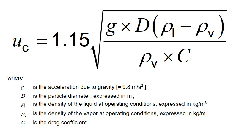
This vertical height is considered from the maximum liquid level. To prevent large slugs of liquid from entering the flare, the vertical velocity of the vapor and gas should be low enough. The dropout velocity (uc), in m/s, of a particle in a stream, is estimated using the following equation:
Step-2: The next step in sizing a flare knockout drum is to take care of the effect that any liquid present in the drum can produce on reducing the volume available for vapor/liquid disengagement. This liquid may result from:
- condensate that separates during a vapor release, or
- liquid streams that accompany a vapor release.
The capacity of the liquid holdup of a flare KO drum is decided based on the consideration of the amount of liquid that can be released during an emergency situation without exceeding the maximum level for the intended degree of liquid disengagement. Different applications require different holdup times. However, the primary requirement is to provide sufficient volume for a 20 min to 30 min emergency release. When it takes longer to stop the flow, longer holdup times may be required.
Locating the Knockout Drum
Flare knockout drums should be located considering the following:
- liquid droplet agglomeration and vapor condensation when there is a long line between the flare stack and the flare knockout drum.
- knockout drum maintenance access during normal and emergency situations.
- thermal radiation effects on flare knockout drum instrumentation and necessity for thermal shielding.
In general, knockout drums are located on the main flare line upstream of the flare stack or any liquid seal. However, if any equipment releases a large amount of liquid to the flare header, additional KO vessels inside the battery limit are installed to collect these liquids. This not only reduces the sizing load of the main flare KOD but also increases product recovery. Knockout drums are also installed ahead of compressor suction to eliminate liquid from entering the compressor.
Maintenance Requirement of Knockout Drums
Knockout drums are considered as dirty service and routine maintenance cleaning of the gauge glasses, checking level instruments, pump shut down instruments, etc must be planned as per vendor recommendations.
What are the types of Knock-out Drums?
Depending on configurations there are two types of knockout drums; vertical and horizontal knockout drums. Again, based on separation capability they are classified as; two-phase knock-out drums and three-phase knockout drums.
What is the burning rain phenomenon?
when a liquid hydrocarbon droplet does not burn completely within the flare flame envelope and the rate of burning is lower than the rate of settling of the liquid droplet, a phenomenon known as burning rain occurs. When burning rain occurs, slugs of liquid are carried over from the flare knockout drum, liquid seal drum, or re-entrainment of liquid accumulated within the flare piping or the flare gas riser.
What is the difference between a Knockout Drum and a Separator?
Knockout drum and separator are used interchangeably. The basic function of both knockout drums and separators are the same. However, from the application point of view, there is a slight difference. Knock-out drums are used in the flare systems or just before compressors for safety concerns and product recovery. Separators have broad applications. They are extensively used in processing plants to separate oil, water, and gas streams for sending for further processing.