Recent Posts

What is Buffing? | Differences between Buffing and Polishing: Buffing vs Polishing

What is Buffing?

Buffing is a surface finishing process to shine metal, wood, or composites. It levels out the residues or excess products to provide a smooth surface and look. The buffing process usually uses a cloth wheel impregnated with loose abrasives as cutting compounds. The cloth buff carries the abrasive compound which removes the superficial material and imperfections to create a glossy uniform surface.

Buffing Process

The buffing operation is usually performed in two steps; an initial cut buff and then a finish buff.

Cut Buffing:

Cut buffing is the coarsest buffing operation. This is the preliminary buffing operation to remove major discontinuities and surface roughnesses. Surface preparation is required before the buffing operation to get better surfaces. With a very good surface preparation, the cutting buff will remove pits, course abrasive lines, deep scratches, etc.

Finish Buffing:

It is the final buffing operation after cut-buffing is performed. This step produces a very good luster on the surface and removes the fine lines generated during cut buffing. Finish buffing is usually quicker, easier, and less pressure process as compared to cut buffing.

Buffing Wheels

Buffing wheels that carry the required abrasive compounds are the transferring agent between the workpiece and the abrasive compound. To get the desired surface smoothness, the construction of the buff should match the workpiece. A harder buff is more aggressive and not flexible and so, usually used for flat surfaces. Whereas a softer buff is ideal for complex shapes as it is less aggressive.

As mentioned earlier there are two types of buffing operations; cut buffing and finish buffing. Both of these operations use different kinds of buffs. Cut buffing operation uses spiral sewn, set up wheels, sisals, and treated airways type of buffs. On the other hand, finish buffs use loose buffs, concentric sewn, airway, and Flannel types of buffs.

Buffing Compound

Buffing compound which is made of binders and abrasives comes in a solid bar or liquid form. Animal fats, grease-less waxes (glue and water), and petroleum-based products are normally used as binders. Proper use of a binder is very important for appropriate buffing operation as the binder decides the cutting ability, hardness, adhesion ability, and lubrication of the buff.

Common abrasive compounds for buffing operation are Aluminum Oxide, Tripoli, Iron Oxide, Silicon Carbide, Calcined Alumina, and Chrome Oxide. The following table in Fig. 1 provides some typical specifications of abrasives used in the buffing process:

Abrasive Specifications for Buffing
Fig. 1: Abrasive Specifications for Buffing

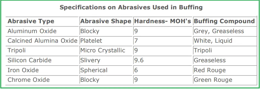
In general, Greaseless Compound, Stainless Compound, and Tripoli are used for cut buffing; while Green Rouge, White Rouge, Reg Rouge, and Calcined Alumina are used for finish buffing.

Surface Speed for Buffing

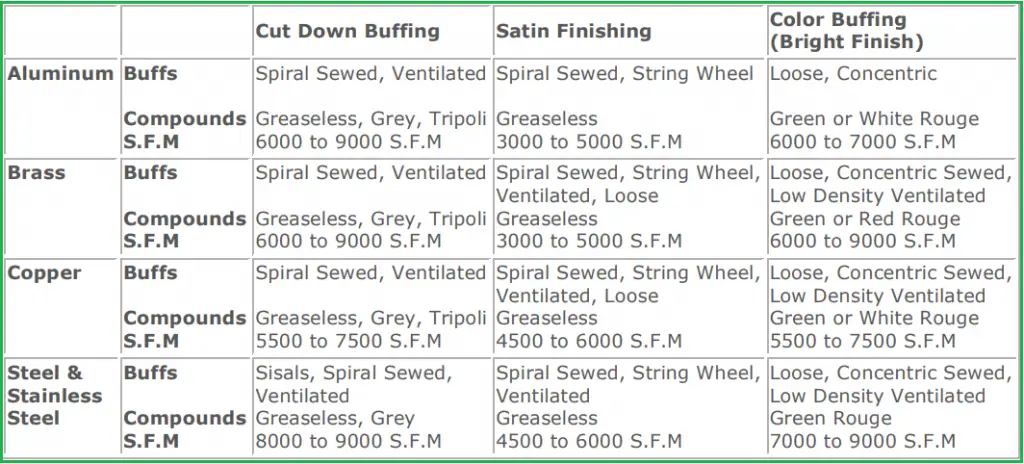
The surface speed is one of the important parameters for the buffing process as it decides the work rate speed, the pressure required, heat build-up, and the actual finish that will be produced. Depending on the material of the buffing operation, the surface speed for the buffing operation is decided. Buffing speed is usually measured in feet per minute or SFM unit. The following table in Fig. 2 provides some typical speed recommendations for various material types.

Surface Speed of Buffing with respect to materials
Fig. 2: Surface Speed of Buffing with respect to materials

What is Polishing?

Polishing is also a surface finishing process performed using abrasives that are secured with glue or other adhesives to the wheel. Polishing is believed to be a more aggressive finishing process as compared to buffing. It has the ability to remove more superficial material from the workpiece surface which in turn allows for a brighter and more polished finish.

Differences between Buffing and Polishing | Buffing vs Polishing

The main differences between buffing and polishing are:

  1. Both buffing and polishing are surface finishing processes. Buffing uses loose abrasives on the wheel whereas polishing uses abrasives that are secured to the wheel.
  2. Polishing is usually performed using a high-grit abrasive whereas buffing is normally performed using a low or medium-grit abrasive.

Applications of Buffing and Polishing Process

The buffing and polishing process is widely used for removing scratches, coatings, oxides, imperfections, pits, etc from the surface of the workpiece. Major applications of the buffing and polishing process are found in:

  • Tools, fixtures, and sports industries
  • Household utensils and appliances sector
  • Automobile, bicycle, motorcycle parts.

References and Further Studies

What is a Pipe Saddle? Its Application, Design, and Configuration

Proper pipe supporting is synonymous with proper working and longevity of the piping and pipeline system. A pipe saddle helps in this activity by supporting the pipe weight. Installing pipe saddles is one of the easiest ways to transfer the pipe’s load generated due to weight, pressure, temperature, and occasional events onto a supporting base. By definition, a pipe saddle is a type of structural pipe support consisting of a saddle and an integral base.

What is a Pipe Saddle?

A pipe saddle is any pipe support that cradles a pipe and transfers the load of the piping system onto secondary members through its supporting base. In the piping industry, a pipe saddle is characterized by two distinct features:

  • A saddle that supports the pipe, and
  • An integral base for transferring the loads from the piping system to the civil structure.

What are the applications of Pipe Saddles?

Pipe saddles serve the following purposes:

  • It elevates pipes. So wherever the pipe is running at an elevation from the support structure, pipe saddles can be used.
  • It can be used to anchor pipes. Similar to pipe shoe supports, saddles can be used to anchor a pipe at the support location.
  • It can be used as adjustable support. Using some special arrangements, piping saddles can be used to work as adjustable support.
  • Pipe saddles can be used to reduce frictional forces by utilizing PTFE or graphite plates in between the structure and saddle bottom. However, special design arrangements must be done for that.
  • Piping saddles can be used to reduce corrosion of the piping system. As with pipe saddles, the pipe will be elevated, and thus the pipe material will not rest on dirty surfaces which in turn will reduce corrosion. Elevating a pipe also separates dissimilar pipe and structural material which reduces the possibility of galvanic corrosion.
  • As with pipe saddles, the saddle rubs on the structural surface during pipe movement, Hence the pipe metal does not get affected by the metallic wear mechanism.

Design Parameters for Pipe Saddles

The factors on which the design of pipe saddles depends are:

Saddle material:

Pipe saddle material should be compatible with the parent pipe material. Also, the material should have sufficient strength to handle the loads generated in the pipe system. The common saddle material is Carbon Steel (CS). However, they can be made of other materials as well. Sometimes, to reduce the cost a combination of materials can be used. For example, to support stainless steel (SS) pipe using a pipe saddle the complete design of the saddle may not use SS material. It can easily use the SS+CS combination to reduce costs. Wherever it touches the SS pipe, the material must be SS but other parts can be of CS material.

Piping Loads:

Piping load is the main important input required while designing saddle supports. The material thickness, strengthening requirement, weld size, etc all will be based on the load that needs to be supported. Loads in all directions must be considered in saddle design.

Thermal movement of pipe at the Support Location:

The maximum thermal displacement at the saddle location must be known while designing the saddle base. The base of the pipe saddle support must be sized such that it does not fall off the structural member due to pipe thermal movement.

Pipe Insulation thickness:

For insulated pipes, the height of the pipe saddle must also consider the piping insulation thickness.

Pipe Saddle Configuration

The following images in Fig. 1 and Fig. 2 are showing typical pipe saddle configurations used in piping systems.

Heavy-duty pipe saddles
Fig. 1: Heavy-duty pipe saddles
Adjustable Pipe Saddle
Fig. 2: Adjustable Pipe Saddle

Equipment Saddles

As saddles have very high load-carrying capability, they are quite popular to use as equipment saddles. They are widely used for supporting horizontal vessels and heat exchangers. Usually, horizontal vessels and heat exchangers are supported by two saddles; One saddle is fixed and acts as a fixed anchor while the other acts as the sliding saddle. The thermal displacement starts from the fixed saddle support and the sliding saddle can axially move. For modeling nozzles of heat exchangers and horizontal vessels during piping stress analysis, both fixed and sliding saddles should be modeled to get proper thermal displacement.

Click here to learn more about Piping Supports

Significance of Space Velocity of Reactor

What is Space Velocity?

In chemical engineering, space velocity refers to the

Space velocity = flow rate of the feeds/ volume of the reactor (or volume of the catalyst)

Space Velocity signifies how many reactor volumes of feed can be fed in unit time (for instance, a reactor with a space velocity of 1 hr−1 is able to process feed equivalent to one time the reactor volume each hour). It is reciprocal of the reactor space-time.

Mathematically, it is expressed as SV = Vo / V. where Vo is the volumetric flow rate of the reactants, and V represents the volume of the reactor or the volume of the catalyst. This expression is the reciprocal of space-time, τ (i.e.  SV = 1/τ).

Types of Space Velocities

There are different types of space velocities which are as follows:

  • GHSV, gas hourly space velocity: It is basically the ratio of volumes of gas present in feed gas at STP/hr to the volume of the reactor or catalyst denoted as gas feed @ scfh/ft3.
  • LHSV, liquid hourly space velocity: It is the ratio of the Volume of liquid present in feed at 60″F/hr to the volume of reactor or catalyst & denoted as liquid feed@ scfh/ft3.
  • WHSV, weight hourly space velocity: It is the ratio of wt of feed/hr to the weight of the catalyst

Among these three types of space velocities, LHSV is frequently used in the oil and gas industry. It has significant impacts on hydrotreating reactions mainly in hydro-desulphurization (HDS), hydro-denitrogenation (HDN), and hydro-dearomatization (HDA).

How does LHSV affect hydrotreating reactions?

As the Liquid Hourly Space velocity (LHSV) is the ratio of the volumetric flow rate (hourly) of the liquid feed to the volume of the catalyst present in the reactor. So, LHSV is reciprocal of the space-time. Reducing LHSV generally results in an enhancement of the hydrotreating reaction. However, an excessive reduction of LHSV can create the operation difficult due to the hydraulic perspective & it can cause channeling which leads to liquid mal-distribution and under-utilization of the catalyst. A significantly high LHSV not only reduces the feed & catalyst contact time but also increases the reactor pressure drop and other hydraulic challenges.

How does LHSV affect feed vaporizations?

The higher the LHSV the faster will be the vaporization of feed as well as H2 dissolution. An increase in LHSV implies a hike in the feed flow rate (liquid). According to Raoult’s Law, with the increase of the mole fraction of a component in a solution, the partial pressure also increases, and consequently the escaping tendency increases. Therefore, more liquid feed is introduced into the reactor, and evaporation rates also become faster. Also, by increasing the liquid flow rate, there is more liquid volume for H2 to dissolve in. Hence, increases in H2 dissolution were observed.

How does LHSV affect conversion?

LHSV, which is the reciprocal of space-time, signifies the time spent in the reactor of the reactants. It was observed that reducing LHSV leads to an increase in the conversion in HDS, HDN, and HDA reactions (see the below figure).

The Effects of increasing LHSV & other parameters on hydrotreating activities.

Variables  TemperaturePressureLHSV
Ranges300-450°C4.5-12.5 MPa0.5-4 h-1
HDSIncreaseIncreaseDecrease
HDNIncreaseIncreaseDecrease
HDAIncreaseIncreaseDecrease

Variation of LHSV & Coke Laydown

The formation of coke is desirable during reaction in the reactor as it reduces catalyst activity tremendously.

As the quantity of catalyst is constant, the only way to vary LHSV is by varying the feed flow rate. A change in feed capacity will change the space velocity & the reactor inlet temperature must be changed to maintain the same severity.

To avoid coke formation the following rules shall be applied:

  • Decrease reactor inlet temperature before lowering the feed flow rate.
  • Increase the feed flow rate before increasing the reactor temperatures.

Calculation of Space velocity

Space velocity especially for hydrocracking & hydrotreating reaction is calculated by conversion of BPSD (rated) into equivalent cubic feet at 60oF i,e (BPSD x 5.615)/24, for a day. The total catalyst volume is to be determined in ft3 by taking the cross-sectional area of the reactor x sum of the vertical heights of a bed of the catalyst excluding the top disc & alumina supported balls.

Another way of calculation is, first convert BPSD to mt/hr, i,e BPSD/(6.29 x S.G of oil @ 60’F) divided by 24 hrs. The volume of (ft3) of active catalyst is converted to weight through the multiplication of the bulk density of the catalyst. Normally loaded density depends on sock loading or dense loading & this density falls between 45 lbs/ft3  sock loading to 50 lbs/ft3 dense loading.

What is space-time in a reactor?

The Space-time of a reactor is defined as the time required to process one reactor volume of feed into a reactor at the inlet condition. It is basically denoted as τ (tau) = V/Vo where V is the reactor volume & Vo is the volumetric flow rate of feed.

Residence time & Space-time

Both times are similar but not exactly the same. Space time is the time needed to process a reactor volume of feed at the reactor inlet condition and the residence time is the average time spent by a reactant particle until it exits from the reactor.

What is a U-bolt? Types, Installation, and Applications

A u-bolt is a u-shaped curved bolt having threads on each end used as support in the piping and pipeline industry. U-Bolts are one of the simplest and most widely used types of piping support. They work mainly as Rest+Guide+Hold down support; though with a little installation, changes can be made to work as line stops as well. U-bolts with their curved shape fit nicely around the pipes which are then secured with a secondary member using nuts. They are easily available in various sizes and thicknesses. The important dimensions of a u-bolt are shown in Fig. 1 below:

Major dimensions of a U-bolt
Fig. 1: Major dimensions of a u-bolt

Applications of U-bolts

U-bolts have an extended range of applications. They are widely used as piping support solutions. The common uses of u-bolts in piping solutions are:

Use of u-bolt as pipe supports:

They are used to provide lateral restraints to pipes. For small-bore piping systems, u-bolts are the most simplest and widely used type of piping support. In any plant, for supporting bare pipes lesser than 8-inch size, u-bolts are extensively used. As already stated they function as rest+guide+hold down. U-bolts are capable to suppress line vibrations by providing rigidity to the system. For supporting vertical elevated runs of pipe, U-bolts are a good choice.

Uses of u-bolts for pipe shipping:

In the pipe and pipeline shipping industry, u-bolts are used to avoid pipe movement and breakage. U-bolts prevent haphazard pipe movements due to transportation loads.

Materials of U-bolts

Even though u-bolts can be manufactured from any type of strong and durable materials; in the piping industry, the following materials are widely used.

  • Plain Carbon Steel, and
  • Stainless steel.

Sometimes, protective coatings are added to prevent corrosion. Some of the usual u-bolt coatings are:

Types of U-bolts: Gripped vs Non-gripped U-bolts

In general, u-bolts are used as guide+hold down. However, they can be used to work like anchors as well. Depending on these u-bolt functions, they are classified into two groups; Gripped u-bolt and non-gripped u-bolt.

Non-gripped U-bolt: U-bolt as Guide

Non-gripped u-bolt is the most common and simple installation to work as the pipe guide. It does not restrict axial movement. In non-gripped pipe u-bolt installation, one nut is placed on the top and the other on the bottom of the support beam. Both nuts are fixed, keeping a gap in between the pipe and the u-bolt surface.

Gripped U-bolt: U-bolt as Anchor

In gripped u-bolt configuration, the u-bolt work as an anchor and stop pipe movement at the support location. To work the pipe u-bolt as an anchor, the u-bolt needs to be installed such that there is no space between the pipe and u-bolt. Both bolts are placed at the bottom of the secondary support structure and tightened to snug against the pipe. The friction force in between the clamp and pipe surfaces restricts the pipe movement in the axial direction to work as a directional anchor. However, with an increase in line stops axial forces, the frictional force may not be able to withstand the axial force and may slip. This is the reason the use of u-bolt as anchors is limited to lower-size pipes; usually up to 6-inch pipes.

Fig. 2: Gripped vs Non-gripped U-bolt

Installation of U-bolts

Installing a pipe U-bolt is very easy. The size of u-bolts is decided based on the pipe OD. All properly sized u-bolts come with threads and nuts. The only job is to drill the hole in the support beam, properly align the bolt through those holes, and tighten the nuts depending on the support type (anchor type or guide type).

What is a Wear Pad? Functions of Pipe Wear Pads

To protect surfaces and improve sliding properties, wear pads are used in industrial applications from earlier days. Also known as slider pads, wear pads increase the wear resistance capability and provide higher strength. In this article, we will explore more details about Piping Wear Pads.

What is a Pipe Wear Pad?

A pipe wear pad is a type of pipe support used to isolate the main pipe surface from direct rubbing with structural surfaces. By installing these on outside pipe surfaces, wear pads for pipe reduce the metal-on-metal damage. Piping wear pads basically replace the contact point from the main pipe to the wear pad material.

What are the Materials used for Pipe Wear Pads?

Wear pads for pipes can be made of metallic or non-metallic/composite materials. Depending on the requirement and temperature of the piping surface, the wear pad material is decided. Common wear pad materials for piping systems are:

Purpose/Functions of Pipe Wear Pads

As the outer surfaces of the piping system are constantly experiencing corrosion, wear, and tear they can be weakened easily. Over time, these can even cause the failure of the components leading to plant shut-down or major hazards. In such a scenario, piping wear pads are one of the easy solutions to reduce corrosion and increase pipe system longevity. The main functions that pipe wear pads serve are:

1. They eliminate metal-to-metal damage. There are two modes of damage that can happen:
Metal-to-metal wear damage by rubbing caused by thermal and pressure fluctuations. Wear pads fit on the pipe’s outer surface on support locations and preserve the pipe material.
Galvanic Corrosion due to dissimilar metals: Galvanic corrosion by the electrochemical reaction can occur when dissimilar metals remain in contact with each other. Pipe wear pads isolate dissimilar materials and discourage galvanic corrosion.

2. Wear pads eliminate the possibility of crevice corrosion of the piping system. When a pipe moves over the structure, the motion can pull off the pipe’s outer layer. So, grooves are created for microbes to creep in, resulting in crevice corrosion by bacteria. Wear pads for piping systems to stop these corrosive cells to form by absorbing the surface impact themselves and safeguarding the pipe material.

3. As wear pads are directly fixed on the pipe, they displace along with the pipe without leaving any scope for dust or grit accumulation on the pipe surface which in turn avoids damages that may be caused by dust or grit particles.

4. Installing composite wear pads does not require welding on the pipe which in turn keeps the pipe system fully intact. They are usually fixed to pipes by extremely strong epoxy adhesives.

5. Composite wear pads absorb the frictional forces within then keeping the parent pipe material safe.

6. Wear pads safeguard the piping systems from damaging vibration effects by providing a damping effect and increasing stiffness. Pipe wear pads help the parent pipe material from banging on the support structures.

So, in a nutshell, wear pads drive long-term performance by reducing corrosion, and wear, and thus preserving pipes.

Installing Pipe Wear Pads

Metallic wear pads are welded with pipe similar to reinforcing pads. Composite wear pads are bonded with pipe using epoxy adhesives. Wear pads can fully or partially enclose the pipe. The image in Fig. 1 shows a typical wear pad used in piping systems.

Pipe Wear Pad
Fig. 1: Pipe Wear Pad

Length of Wear Pads

The minimum length of pipe wear pads is calculated as follows:

  • For wear pads with line stops the minimum length of wear pad=structure (beam) width+2*each line stop member dimension+2*one side gap for line stop+50 mm.
  • For wear pads without line stops the minimum length of the wear pad= structure (beam) width +maximum thermal movement at that support location+50 mm.

When to use Wear Pads?

Pipe wear pads are extensively used during the following situations:

Use of Metallic Wear Pads:

  • Metallic wear pads are used for strengthening thin-walled pipes to avoid local damage in support locations.
  • If piping support is experiencing a relatively higher load then wear pads are suggested to safeguard the pipe from support load reaction.
  • Wear pad supports are normally suggested for line stops with relatively high loads. In many consultancy organizations, it is a standard engineering practice to use wear pads for all pipe supports of pipes exceeding 24-inch size.

Use of Composite Wear Pads:

Composite wear pads are widely used for

  • reducing corrosion.
  • damping vibration.

Difference between RF Pad and Wear Pad

The main differences between reinforcement pads and wear pads are

RF pads or Repads are used for pressure integrity. When a piping system is not able to withstand pressure stresses locally due to removing metal for branch connection or high stresses, Repads are used to provide local strengthening. Reinforcing pads are usually provided in equipment nozzle connections, pipe branch connections, or trunnion connections.

On the contrary, wear pads are used as pipe supports. They provide wear resistance and high strength to pipes in support locations.

What is a Pipe Anchor? Its Definition, Types, and Functions

A pipe anchor is a type of pipe support that is used to control pipe movements by fixing the pipe with secondary civil structures. Piping anchor supports are very important in piping and pipeline systems. The complete thermal behavior of the piping system is decided by the location of the pipe anchor supports. For proper control of thermal expansion and contraction, there is no alternative to pipe anchors. In this article, we will try to understand the basics of pipe anchor supports.

Types of Pipe Anchors

Depending on the restriction pipe anchor supports provides to piping at the support location, they are classified into two groups:

  • Fixed pipe anchors or Full anchors, and
  • Directional pipe anchors.

Fixed Pipe Anchors

As the name suggests, Fixed pipe anchors fix the pipe at that location. We all know that a point in space has six degrees of freedom. Three in the translational direction and three in the rotational direction. Fixed pipe anchors restrict the pipe from moving in all six directions. In actual applications, the pipe at that location is either directly welded or bolted to the support beam so that the pipe can not move in that location. As the pipe is fully restricted at this location depending on the piping configurations forces and moments in all six directions will be generated. So, these types of pipe anchors must be designed considering forces and moments from all directions. Fixed pipe anchors are rarely used in piping systems. Usually, they are preferred for high vibration-prone lines, near pressure control valves, blowdown valves, locations where thrust force can generate, etc.

Typical Fixed and Directional Pipe Anchor

Directional Pipe Anchors

Directional pipe anchors arrest the movement only in the pipe longitudinal direction. In all other directions, piping directional anchors allow movements. They are also popularly known as line stop supports, axial stop supports, or limit stops. These types of supports usually experience only vertical and axial forces and are easier to design. In pipe and pipeline systems, pipe directional anchors find wide applications. One of the most widespread applications of directional pipe anchor supports is in the design of expansion loops. On either side of the pipe and pipeline expansion loops, one line-stop support is provided.

Locating Pipe Anchors

Deciding the locations of pipe anchors are very important. The best location to use anchor supports is at the neutral points of piping and pipeline configurations. Locating pipe anchor supports near-neutral points will provide the lowest thermal loads. However, it is not always possible to locate piping anchors at the neutral point. So, depending on the requirement, these supports must be judiciously located to safeguard the pipe system.

Functions of Pipe Anchors

Piping anchor supports in a piping and pipeline system usually serve the following purposes:

  • It helps in the proper distribution of pipe thermal displacements.
  • It provides sufficient rigidity to the piping system to avoid the damaging effects of vibration.
  • It safeguards the pipes from detrimental seismic, wind, and other dynamic events.
  • Pipe anchors are extensively used to absorb thrust forces, PSV reaction forces, Slug and Surge forces, etc.
  • It helps in equipment nozzle load qualification by limiting pipe movements to the equipment.
  • Pipe anchors help pipe stress engineers in pipe system breaking. So, the whole plant can easily be broken down into a number of smaller systems, thus helping the stress engineers in easy handling and analysis.
  • Pipe anchors are also used for scope demarcation between vendors to decide boundary conditions for each client of the same project.
  • By controlling the pipe movements as per design requirements, pipe anchors improve the performance and longevity of the piping and pipeline system.

Factors affecting Pipe Anchor Design and Installation

While designing and installing a pipe anchor in pipeline and piping systems, the engineer should pay attention to various factors like:

  • Pipe Support material: When welding directly to the pipe, anchor material should be compatible with the pipe material to avoid galvanic corrosion. For all other cases, the anchor support material should be of sufficient strength to resist all the loads arising due to pressure and temperature fluctuations in a pipe.
  • Support loads: For deciding member sizes of pipe anchors actual loads must be considered. Usually, pipe stress engineers provide loads experienced by pipe supports after pipe stress analysis.
  • Corrosion resistance: Sometimes, to reduce the effects of corrosion, pipe anchors may be equipped with hot-dip galvanizing, anti-corrosive materials, or protective coatings.

Click here to know more about pipe supports