What is a Rigging Equipment?
Rigging equipment refers to the mechanical devices and elements used to lift heavy loads and maneuver objects safely, as part of a planned system implemented by a team of riggers. Rigging is a technical trade that encompasses a variety of components to securely distribute the load in question. Properly designed and selected rigging equipment facilitates the moving process to ensure that the rigging procedure is completed successfully with care, precision, and patience. Various industries including construction, engineering, manufacturing, and event staging often require the services of rigging equipment.
Examples of Rigging Equipment
Rigging equipment includes all elements and devices used to hoist, push, lift, and pull large objects. Rigging equipment is the devices that securely distribute the weight of the lifted objects safely onto the moving devices. Depending on the type of rigging job the type of rigging equipment and moving devices varies.
For example, a jack is used for lifting but skates and dollies are used for pushing. Similarly, chains, hooks, and tie-downs are used for pulling but chain hoists are used for lifting. For handling heavy objects, cranes, forklifts, twin lifts, and risers need to be used as the capacities are more. For securing heavy objects onto a crane, rigging equipment is required. Rigging equipment has the diverse capability. They are specialized for moving the load in any environment. Some examples include chain slings, wire rope slings, webbing slings, metal mesh slings, spread beams, and various rigging hardware.
Using the right kind of rigging equipment is very important for shifting and moving loads safely. Rigging hardware plays an equally significant role in this respect as they ensure that the entire process gets completed in a secure and flawless manner.
Types of Rigging Equipment
While moving a heavy object, there are many important things that must be considered. One such consideration is the type of rigging equipment to use. As there are many different types of rigging equipment available for moving a heavy object or equipment, the specific job type dictates the selection. Every rigging job is different, so one must have extensive knowledge of all rigging tools and practices. The following paragraphs provide a short description of some of the most important and frequently used rigging equipment.
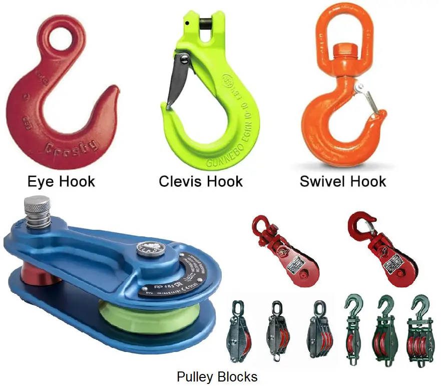
Rigging Hooks as Rigging Equipment
Rigging hooks are required for lifting heavy equipment. These hooks are specifically designed to eliminate the risk of slippage. Usually, steel is used to manufacture rigging hooks. They come in different sizes and designs for lifting different types of loads. The hook opening is known throat. The sizes of the throat range from 5/8 inches to 1 17/32 inches. Sorting, clevis grab, eye, choker, etc are typical examples of some of the different types of rigging hooks.
Rigging Equipment-Pulleys and Blocks
Pulleys and lifting blocks are usually used to lift very heavy objects. These devices help in reducing the required force for lifting and moving heavy equipment. Snatch blocks, swivel blocks, square blocks, tilt-up blocks, etc are examples of a few different types of lifting blocks. To aid in the lifting operation, lifting blocks come in a variety of sizes and load-carrying ranges.
Pulleys are categorized as single and double-pulley systems. They are used with rigging ropes that circle the pulley for hooking heavy objects for lifting. Industrial Pulleys vary based on frame, rope, and sheave size. Wire rope is widely used with lifting blocks, while synthetic rope is usually used with pulleys as lifting blocks generally carry heavier loads than pulleys.
Shackles as Rigging Equipment
Shackles allow different types of rigging equipment to be quickly connected and disconnected from one another. For loads ranging from 6,000 pounds to 11,000 pounds, shackles are normally preferred. Broadly, shackles are of two types, anchor and chain. Both of these two categories can also include sub-categories of shackles like screw pin, safety, and round pin types. Shackles usually involve a steel loop that is closed by a pin, allowing a secure connection between rigging equipment during the moving of heavy equipment. Shackles come in a size ranging from 3/16″ to 2 1/2″.
Eye Bolts
Eye bolts in rigging configurations act as anchor points for looping cables or ropes. Available in a wide variety of different sizes and materials, they are capable to accommodate different types and sizes of loads. There are various types of eye bolts of which straight eye bolts and shoulder eye bolts are the most common types. For straight-line applications, straight-eye bolts are used, while angular connections use shoulder-eye bolts. U-bolts, screw eye bolts, lag eye screw bolts, etc are some other types of eye bolts.
Steel Nuts
Eye bolts use stainless steel nuts. Depending on the weight of the load to be lifted and its shape, the size of the nuts varies. Some of the most widely used nuts in rigging applications are hex nuts, dome nuts, lifting eye nuts, ball ends, and wing nuts. Made of type 316 stainless steel, these nuts can typically be found in both RH and LH thread for this type of rigging equipment.
Wire Ropes and Accessories
For rigging and moving heavy equipment, Wire ropes are useful as they have the good capability. To increase the strength, a carbon steel wire or stainless steel wire is added in a helix pattern. To protect them from the outdoor elements, Wire ropes can be coated or galvanized. They come in multiple sizes and have a variety of specifications. Widely used, wire ropes are 6×19, 6×36, 6×26, 7×7, and 7×19. Wire ropes are used in conjunction with various accessories like thimbles, clips, sleeves, and stops. These rigging equipment accessories increase the functionality of the rigging tasks.
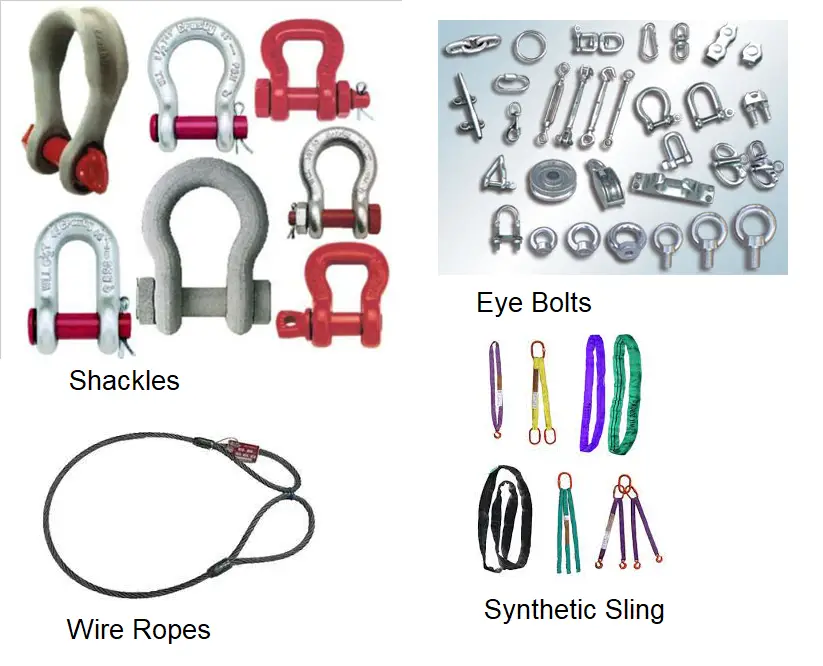
Synthetic Lifting Slings
This type of rigging equipment is manufactured from synthetic material. They usually have lower capabilities as compared to ropes. That is the reason while moving heavy loads, synthetic slings are used along with wire ropes. Two types of lifting slings are the most common. They are endless slings and eye-and-eye slings. Endless slings are made of simply synthetic material in a loop. But eye-and-eye slings use triangular, flat, or twisted ends and are made of either metal or synthetic material. These slings add additional strength for bearing heavy loads and help balance rigging jobs.
Inspection of Rigging Equipment
For proper functioning of rigging equipment in a safe and secure manner, these need periodic inspection, maintenance, and repair. As all rigging equipment is used in harsh environments and operations, there can be stress and strain on the parts which must be repaired prior to the next use. Usually, every company maintains a schedule for maintenance and inspection based on manufacturer guidelines and experience. This periodic inspection will ensure the safe, trouble-free operation of rigging equipment.