Being a piping engineer you must be familiar with the term “Piping Shoe”. Pipe shoe supports are highly popular for insulated lines. As insulation material is usually not capable to withstand high piping loads, piping shoes are used to transfer the piping loads to secondary civil structures without damaging the insulation.
What is a Piping Shoe?
A pipe shoe is a special type of pipe support structure made of structural members or plates with a flat base. Pipe shoes find major applications for supporting the following pipes:
Pipe shoes act as an intermediate member between the pipe and the secondary steel structure and serve the following purposes:
They stop pipes/ insulation from rubbing against structures thus preventing damage to insulation material.
By separating the pipe and structure materials separate, they help in preventing galvanic corrosion in case of dissimilar material.
Pipe shoes help to increase the structural life by not transferring the high pipe temperature to the structure.
Pipe shoes help in preventing pipe damage for thin-walled pipes in support locations by transferring the loads to structures.
Types of Pipe Shoes
Pipe shoe supports are categorized based on various parameters as provided below:
Depending on the material of construction, pipe shoes are classified into two types: Metallic pipe shoes, and composite pipe shoes.
Metallic Pipe Shoes
As the name suggests, this type of shoe is made from metals. This is the most common type of piping shoe support used in the process and power piping industries. Metallic piping shoes are the oldest type of piping shoes that serving the piping industry for decades. Traditionally, metallic pipe shoes are manufactured from I-beams, channels, or structural plates. Metallic pipe shoes are simple and low-cost piping support solutions for high-temperature piping systems.
Composite Pipe Shoes
Composite pipe shoes offer the best corrosion-resistant alternative to metallic pipe shoes. They are usually UV resistant, strong, and durable. They are a relatively new addition to pipe shoe groups.
Depending on the attachment of pipe shoes to the parent pipe, they are classified into two groups: welded shoes and clamped shoes.
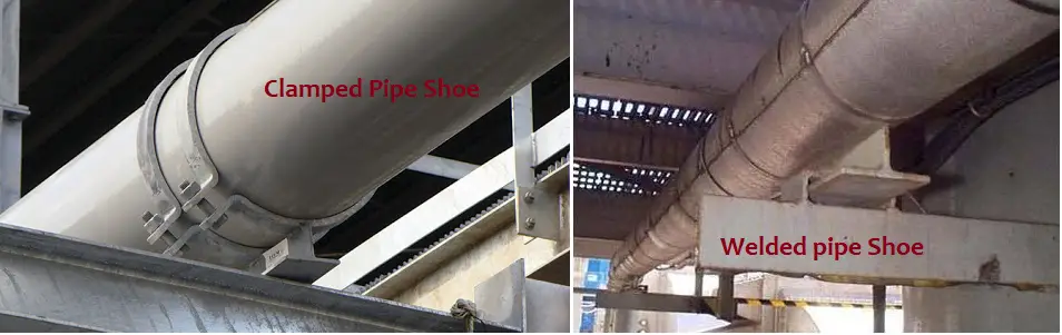
Welded Pipe Shoes
When pipe shoes are directly welded to the pipe, they are known as welded pipe shoes. Welded pipe shoes are normally used for carbon steel pipes for which welding is easy and cheaper. Welded pipe shoes have very high load-carrying capabilities and are suitable for axial and lateral loads.
Clamped and Welded Pipe Shoe
Clamped pipe Shoes
For certain material, direct welding in pipes are not permitted or welding is costly and difficult. In such a scenario, clamped pipe shoes are used and the pipe shoe is welded on the clamps. For galvanized pipes, stainless steel pipes, DSS pipes, etc clamped pipe shoes are used. Parent pipe-compatible clamp material is chosen so that no galvanic corrosion occurs and then the shoe material is welded on the outside surfaces of the clamps. Clamped piping shoe supports, in general, carry lower loads as compared to welded counterparts. Clamps pipe shoes are not advisable to use as axial stops or line stops.
Depending on the construction, pipe shoes are of two types: T-type shoes and Saddle-type shoes.
T-type Piping Shoes:
They are usually used for pipe shoes having lower loads. Usually, pipes with a size of less than 26 inches use T-type pipe shoes.
Saddle-type Pipe Shoes:
Saddle supports are used for pipes with sizes exceeding 24 inches. They are suitable for carrying high loads.
Deciding Pipe Shoe Lengths
It is a better engineering practice to standardize pipe shoe designs. In most plants, a shoe length of 300 mm is normally used for pipes up to 24-inch size, and a length of 500 mm is used for pipes with diameters exceeding 24 inches. However, depending on the thermal movement at the support location the shoe length needs to be adjusted.
For example, a 300 mm long pipe shoe will support the pipe over the structural member up to a 150 mm longitudinal pipe movement. If the pipe movement is more than 150 mm, then the length of the pipe shoe should be increased accordingly so that the pipe support does not fall off the structural member.
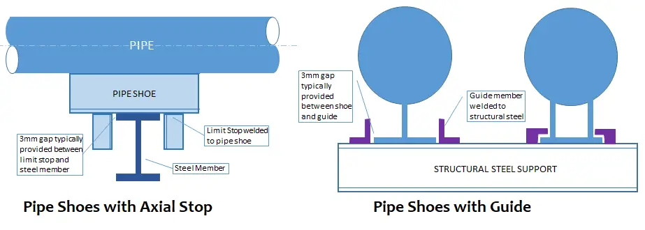
Also, the shoe supports with line stop members usually require more lengths than the standard pipe shoe lengths. So, based on the dimensions of the secondary structural member and line stop member the pipe shoe length needs to be increased.
Pipe Shoe support with Guide and line Stop
Factors affecting Pipe Shoe Design
The main parameters that affect the design of pipe shoes are
Expected Support loads: Members need to be designed based on these loads.
Pipe Insulation thickness: Pipe shoe height is decided based on the pipe insulation thickness. Normal practice is Piping Shoe Height=Pipe Insulation thickness (mm)+25 mm.
Thermal Displacement at the support location to decide shoe length.
Support type in the location: For example line stop supports will require more lengths.
Shoe material: To be compatible with pipe material.
There are two other terms that are often associated with pipe shoes; Hot Shoe and Cold Shoe.
Hot Shoes: Hot pipe shoes usually refer to pipe supports for high-temperature piping systems.
Cold Shoes: A cold shoe normally refers to a support component that incorporates an insulating material that attaches directly to the pipe. This pipe shoe with insulation functions as a load-bearing component for transferring the pipe load to the structure.
PSI is the most basic unit for measuring pressure in the FPS unit system which is widely used in the United States and European countries. Most of household sporting goods, pressure transducers, etc use the unit PSI which stands for pounds per square inch. PSI signifies the pressure resulting from one pound-force applied to one square inch area. The mathematical symbol for PSI is “lb/in2” and it expresses the unit of pressure or stress. One psi is approximately equal to 6,894.75729 Pa (Pascal)
There is two widely used specific form of pressure measurement under PSI. They are PSIA and PSIG.
What is PSIA?
PSIA is the most common and referenced form of pressure measurement that stands for pounds per square inch absolute. Absolute pressure is defined as the pressure relative to zero or absolute vacuum. PSIA is used on engineering documents like P&IDs.
What is PSIG?
PSIG which stands for pounds per square inch gauge is also used extensively. Gauge pressure is defined as the pressure relative to the ambient atmospheric pressure. PSIG is used for instrument pressure gauges in equipment, oilfield valves, regulators, etc.
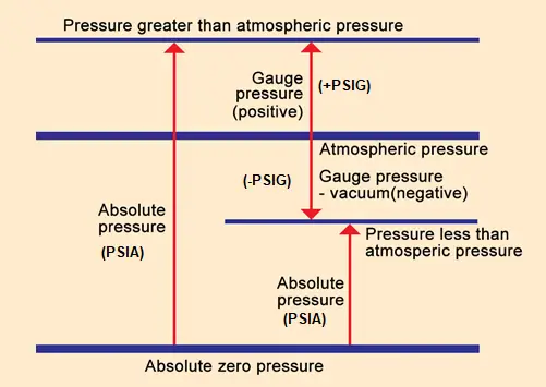
Refer to the image in Fig. 1 that clearly explains the concept of PSIA vs PSIG and absolute pressure and Gauge Pressure.
Fig. 1: PSIA vs PSIG
What are the differences between PSIA and PSIG? PSIA vs PSIG
From the above discussion, we can interpret the main differences between PSIA and PSIG as follows:
PSIA is the unit of pressure measurement in the English system relative to absolute zero or full vacuum pressure (0 PSI) whereas PSIG is the unit of pressure measured relative to atmospheric pressure.
PSIA is always greater than PSIG.
PSIA indicates the total pressure, whereas PSIG indicates the pressure relative to the atmospheric pressure at the location. In absence of data at the exact location, the atmospheric pressure of sea level (14.7 PSIA) can be used.
PSIA does not change with altitude but PSIG changes with a change in altitude as less air molecules will be present at higher altitudes to create pressure.
PSIA can never be negative but PSIG can be negative. Vacuum pressures in PSIG below atmospheric pressures are negative.
How do I Convert PSIG to PSIA? | PSIA to PSIG and PSIG to PSIA Conversion
It is easy to convert from PSIA to PSIG and vice versa. The formula that describes the relationship between PSIA and PSIG is:
So by knowing the atmospheric pressure of any location, you can easily convert pressure from PSIA to PSIG or vice versa. At sea level, the above equation can be written as
PSIA=PSIG + 14.7 PSIG=PSIA-14.7
Should I use PSIA or PSIG?
If the measured pressure is not affected by the changes in atmospheric pressure then you should use PSIG or gauge pressure. Some typical applications are for measuring pneumatic pressure, hydraulic pressure, or the level of liquid in an open tank, etc. The P&ID and Line lists of oil and gas industries usually provide pressures as PSIG.
On the other hand, if the atmospheric pressure affects the measured pressure then you should go for measuring absolute pressure or PSIA. For example, To measure pressure in a closed system or closed container, To measure the atmospheric pressure (weather prediction), and To assess altitude in aeronautical applications, you should use an absolute pressure gauge to measure PSIA. Research laboratories, Food packaging industries, etc use PSIA extensively.
Is 0 PSI a Vacuum?
A vacuum is defined as a partially exhausted space. Vacuum pressure is defined and measured relative to the ambient atmospheric pressure. Usually, air pumps are used to remove air from a confined space and thus create a vacuum. We learned that 1 atmosphere is roughly 14.7 PSIA. So, if the atmospheric air is removed from the space the pressure will fall below 14.7 PSIA and the Vacuum will start to create. Once, the full air is removed from a confined space, it will reach 0 PSIA which is known as the full vacuum.
Various Types of Pipe Clamps for Piping and Plumbing Industry
Pipe clamps are widely used for supporting suspended pipes. They are also used to work as clamped pipe shoes. Pipe clamps can be defined as bolted circular or semi-circular pipe attachments that clamp around a pipe and connect the pipe with other assembly components for proper support. These piping clamps transfer loads of the piping system to the structure. A wide variety of piping clamps are available to use as pipe support attachments.
Types of Pipe Clamps
Depending on the purpose, materials, function, use, etc, a wide variety of piping clamps are used in industrial applications. Some of the different types of pipe clamps are explained below:
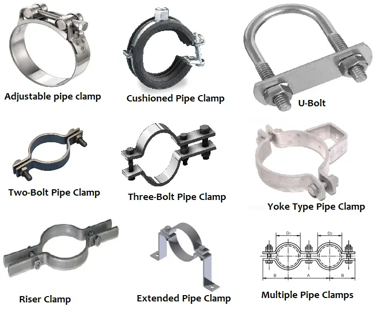
1. Adjustable Pipe Clamps:
Mostly made from Steel, plastic, or aluminum, these types of piping clamps have the ability to adjust themselves as per the required pipe diameter. They can be easily tightened or loosened as per the pipe OD. As these types of pipe clamps can be universally used for different pipe diameters, they are cost-effective.
2. Cushioned Pipe Clamps:
Containing a cushioning material these type of pipe clamps helps in avoiding galvanic corrosion as metal-to-metal contact is prevented. Widely used for bare pipes, these pipe clamps shall be selected depending on the pipe temperature as the cushioning material should sustain that temperature.
3. Rigid Clamps:
Simple in construction, Rigid clamps are usually made from steel or iron. They are available as single-body pipe clamps or two-piece pipe clamps and can easily be screwed.
4. U-bolts:
U-bolts are the most widely used type of pipe clamps. U-bolts are extensively used for small-bore piping. They are used to work as rest+guide+hold down or rest+guide+hold down+line stop for small bore piping systems. For pipes with a diameter exceeding 8 inches, their application is reduced to a great extent as the piping loads increase with the increase in pipe sizes.
5. Two-Bolt Pipe Clamp:
Two-bolt pipe clamps are used for hanging bare pipes without any insulation. Their load-carrying capability is usually not large.
6. Three-Bolt Pipe Clamp:
Three-bolt Pipe Clamps are used for suspending insulated lines carrying high-temperature fluids. The length of the clamps on top of the pipe is increased to accommodate the 3rd bolt which allows the attachment of the pipe clamp outside the insulation. The load-carrying capability of three-bolt pipe clamps is relatively higher than two-bolt pipe clamps.
7. Yoke-Type Pipe Clamp:
For hanging of high-temperature horizontal insulated pipes, yoke-type pipe clamps are used. These types of pipe clamps can easily support pipes with 4″ – 6″ insulation.
8. Riser Pipe Clamps:
Riser Pipe Clamps are used to support lines without the use of hanger roads. The pipe loads are transferred by resting both ears of the clamp on the floor or structural member. These types of pipe clamps are not recommended for higher temperatures.
Fig. 1: Various Types of Pipe Clamps
9. Pipe Clips:
Also known as pipe straps, pipe clips are used to support horizontal or vertical lines by bolting the clip directly to a structure.
10. Heavy-Duty Pipe Clamps:
Heavy-duty piping clamps are specially designed to support higher piping loads. Most of the pipe clamps are designed in both standard and heavy-duty variants to address different load requirements.
11. Extended Pipe Clamps:
In some applications, the bottom piece of the pipe clamp can be extended and configured to use as a pipe support. These types of piping clamps are known as extended pipe clamps.
12. Multiple Pipe Clamps:
In certain special applications, two or more pipe clamps can be joined together or manufactured to use multiple pipe clamps to support more than one pipe. Multiple pipe clamps are specially fabricated to suit the site requirements.
Selecting a Pipe Clamp
Selecting a pipe clamp for a specific application required considering various parameters. Some of these factors are:
Pipe Material:
Normally the clamp material should be compatible with the pipe material. For example, a SS pipe needs an SS clamp to avoid galvanic corrosion.
Pipe Temperature:
Pipes expand or contract based on the temperature variation of the pipe material. So, the clamps selected should be able to withstand those temperature fluctuations.
Load Bearing Capability:
Clamps should be selected based on the applicable piping loads. Normally, all manufacturer’s catalogs specify the maximum load-carrying capacity of both standard and heavy versions of pipe clamps. So, piping clamps must be selected after calculating the pipe support loads. Normally, clamps are avoided for axial load applications like the application as line stops. But in some small-size lines fixed u clamps are used as line stop supports. Also, sometimes clamped pipe shoes are used as line stops. In those cases, the magnitude of axial loads must be checked and suitable additional arrangements must be done if required.
Pipe Outer Diameter:
Pipe size or outer diameter also affects the pipe clamp selection. Usually, clamps are manufactured for a certain minimum to maximum pipe diameters. So, while selecting pipe clamps those need to be checked in the manufacturer’s catalog.
Working Environment:
The type of pipe clamps is also affected by the working environment where the piping clamps will be installed. As pipe clamps will be exposed to the environment, the proper coating must be provided to avoid corrosion.
Special Requirements:
Pipe clamps may require special functions like having rubber lining or absorbing noise. So, according to special functions that need to be performed clamps need to be selected.
Deciding the Size of Pipe Clamps
The size of pipe clamps is decided based on:
Pipe outside diameter: As pipe OD is fixed for metallic pipes, clamps are decided based on the pipe’s outer diameter. For plastic pipes however the OD may vary from manufacturer to manufacturer which will decide the selection of piping clamps.
Special Consideration: Sometimes, it may be required to use clamps over pipe insulation, in those cases insulation OD must be calculated while deciding on pipe clamp size.
Pipe Clamp Materials
Pipe clamps are manufactured of a wide range of materials like:
Carbon Steel
Stainless Steel
Plastic
Copper
Brass
Aluminum
Alloy Steel
Chrome/Chrome-Plated pipe clamps, etc
Features of Pipe Clamps
Most pipe clamps provide the following features:
Simple Operation
Easy installation
Adjustable in a small range
Nice appearance
The temperature range is decided by the clamp lining being used.
All piping materials expand or contract when exposed to temperatures greater or lower than the installation temperature. As the temperature of the pipe material increases due to fluid temperature or sun/flare radiation, the pipe expands. Again, pipes contract as temperature decreases. Depending on the pipe materials, this pipe expansion or contraction varies. If this piping expansion or contraction is not addressed during the design of the piping system, it may lead to costly piping issues. In the world scenario, the piping system may fail and can be hazardous. Plant piping systems are usually exposed to very high temperatures and pressures. So, it is obvious that the length fluctuation from the maximum design temperature to the minimum design temperature must be taken care of during the piping system design for the safety and reliability of the system.
For example, if a pipe run is fixed at both ends and is heated, the liner pipe expansion due to temperature change will create compressive stresses on the pipe material. If the generated stress becomes so high that it exceeds the pipe material’s allowable stress, it may result in damage to the pipe, supports, or piping components. Depending on the severity of that damage, the plant may be required to go for a temporary shutdown to conduct repairs or replace the piping system prematurely.
As piping expansion and contraction due to temperature changes are unavoidable, the generated pipe thermal displacement must be absorbed in the piping system itself. There are methods by which piping expansion and contraction can easily be accounted for during the piping system design. In this article, we will learn the procedures to deal with pipe thermal expansion and contraction issues.
How do you calculate the Thermal Expansion or Contraction of a Pipe?
There are three parameters on which piping expansion or contraction depends:
Coefficient of thermal expansion (α): This parameter provides the amount of pipe linear expansion because of each unit change in temperature. The values of the thermal expansion coefficient are different for different materials. So, For the same length of pipe, the amount of expansion will be different for CS, SS, Aluminum, Copper, or Plastic pipes. So, indirectly piping thermal expansion depends on pipe material.
Length of Pipe/Pipeline Run (L): The more the length of the pipe, the more will be pipe expansion or contraction.
Temperature Change (∆T): Plant piping systems are designed from maximum design (hottest) temperature to minimum design (coldest) temperature throughout their service life.
The amount of thermal pipe expansion /contraction (∆L) can be calculated using the following equation:
∆L = L α ∆T (All values must be entered with the consistent unit)
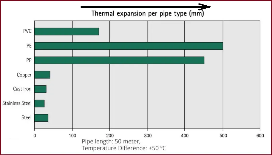
The following chart (Reference: walraven.com) gives an idea of how different pipe material expands with respect to temperature change. The chart is prepared considering a 50-meter pipe run with a +500C temperature differential.
Fig. 1: Pipe Thermal Expansion Comparison
Factors of the Material to Handle Generated Stress
To design for pipe expansion or contraction one needs to understand the following pipe material qualities:
Working Stress
Working stress is the maximum stress that the pipe material can handle during operation. All piping materials have the ability to withstand some degree of pipe expansion/contraction without sacrificing their structural integrity.
Modulus of Elasticity
The modulus of elasticity denotes the stiffness of the pipe material. It is an intrinsic property of the pipe material which provides the ability to elongate or compress upon the application of a force.
Pipe Outside Diameter
The pipe’s outside diameter affects the ability of the pipe to deflect stress. With an increase in pipe diameter, the rigidity increases and it is very difficult to deflect a rigid pipe.
How do you control pipe thermal expansion?
The best way to control the pipe thermal expansion or contraction is to design the piping system to account for it. The following paragraphs will explain the required steps.
Designing Pipe Systems for Thermal Expansion and Contraction
As mentioned earlier that the piping expansion and contraction issues need to be dealt with during the design phase to avoid significant problems at a later stage. There are four deflection mechanisms that can be employed to accommodate the pipe expansion inside the piping/pipeline system without losing integrity and reliability. These are:
The pipe route usually does not follow continuous straight lengths. Naturally, all piping and pipeline systems include changes in direction. These directional changes are a natural way of accommodating pipe thermal expansions within the piping system. If required, additional directional changes can be deliberately added by including pipe elbows and bends. The length of the pipe that runs perpendicular to a given pipe run is called the absorbing length. For example, if a pipe is running in the X direction; then adding pipe legs in the Y or Z direction is regarded as the absorbing length. The elbow along with the adjoining pipe allows some degree of thermal expansion. This required perpendicular leg length can easily be determined following the guided cantilever method.
Pipe Offsets to deal with Piping Expansion:
Expansion offsets are usually placed in the center of a pipe run. Each elbow accounts for some degree of pipe expansion. When it is required to absorb a small amount of thermal expansion or contraction pipe offsets work fine.
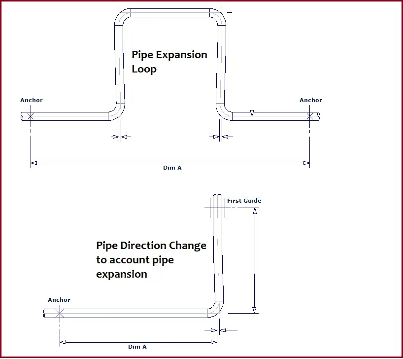
Pipe and Pipeline Expansion Loops:
Piping expansion loops are the widely used deliberate method to handle pipe expansion and contraction issues. Expansion loops can easily accommodate large pipe deflections. The required leg length is calculated using the guided cantilever method. anchors are provided on both sides of the expansion loop to direct the pipe expansion inside the expansion loop. There are various types of expansion loops that a piping or pipeline system can employ. More details about the pipe expansion loops are provided in the following article: Expansion Loops on the Piping or Pipeline Systems.
Fig. 2: Dealing with Pipe Thermal Expansion
Expansion Joints to handle Pipe Thermal Expansion:
Expansion joints are mostly used in tight, enclosed areas when including expansion loops or offsets is not possible. Expansion joints are specialized assemblies that can absorb pipe thermal expansion or contraction. This is usually an expensive option and is used as a last resort. Most project specifications and codes instruct to avoid the use of expansion joints as much as possible. Click here to learn more details about pipe expansion joints.
Tutorial Video on Pipe Expansion Loop
Refer to the following video tutorial to learn more about pipe and pipeline expansion loops.
What is Pressure Reducing Valve? Its Types, Applications, and Advantages
A pressure-reducing valve is a self-operating valve that is used to reduce any excess pressure in a system. Sometimes this valve is also known as pressure reducing regulator. The basic function of pressure-reducing valves is to reduce higher pressure into lower. They are commonly used in water, steam, and oil & gas industries. A Pressure Reducing Valve can be defined as a self-acting automatic control valve for reducing a higher unregulated inlet pressure to a constant, reduced outlet pressure regardless of the fluctuations in the upstream water pressure. In this article, we will learn about the functions, types, applications, and advantages of pressure-reducing valves.
Functions of Pressure Reducing Valves
A pressure-reducing valve is able to control pressure through the fully automatic self-contained operation without the necessity of an external power source. The main functions of a pressure-reducing valve are:
In steam systems, pressure-reducing valves are used to get precise control of downstream pressure. These valves automatically adjust the valve opening and adjust the pressure to keep it constant during pressure fluctuations.
Properly selected pressure-reducing valves can be used for water hammer protection under defined conditions.
They can also be used as bypass valves for saving the system during power failures.
Pressure-reducing valves are capable of taking rapid action by immediate sensing and adjusting based on the downstream pressure.
Types of Pressure Reducing Valves
A pressure-reducing valve in a steam system works by balancing the steam pressure with a spring. Most of the modern pressure-reducing valves are manufactured using this basic concept. Based on the mechanism of controlling the valve opening, pressure-reducing valves are classified into two types:
Direct acting pressure reducing valve and
Pilot-operated pressure-reducing valve.
Direct-acting pressure-reducing valve:
Direct-acting pressure-reducing valves are ideal for small loads where precise pressure control is not required. They are manufactured in a compact size, cheap, and very easy to install. However, they usually have more variation from the set pressure as compared to their pilot-operated counterpart.
Direct-acting pressure-reducing valves are designed for point-of-use installation. This is the simplest type of pressure-reducing valve that operates with either a flat diaphragm or convoluted bellows. It does not need an external sensing line downstream to operate as it is self-contained. The accuracy of direct-acting PRVs is typically (+/-) 10% of the downstream set point.
In direct-acting pressure-reducing valves, the movement of the adjustment spring aids in the valve opening directly. The spring compression creates an opening force on the pressure-reducing valve which increases the flow. As pressure builds downstream, equalizing occurs by feeding the downstream pressure to the underside of the adjustment spring where its upward force counter-balances against the spring compression. The spring compressive force is limited to allow sufficient spring sensitivity to equalize with downstream pressure changes. This causes a simple pressure control through a valve orifice. However, high flow rates can cause pressure variation.
Pilot Operated pressure reducing valve:
Pilot-operated pressure-reducing valves are normally used for larger loads requiring close pressure control. They provide a faster response to load variation and are suitable for a wider range of flow rates as compared to the direct-acting types. They are larger in size and costly.
A pilot-operated pressure-reducing valve uses a pilot valve to load a piston or diaphragm that increases the downward force used to open a larger main valve. This helps in larger flow capacity with a lower pressure variation. By balancing the force between the adjustment spring and the secondary pressure, the opening and closing of the pilot valve are controlled. This pilot valve purposely delivers pressure to the main valve piston or diaphragm. The downward force created by this pilot flow pressure is amplified by the area of the piston or diaphragm that enables the opening of a much larger main valve providing the ability for very high flow rates.
Due to this amplification, a small change in the opening on the pilot valve results in a large change in flow and downstream pressure through the main valve. Therefore, a little change in adjustment spring force on the pilot accomplishes a quick response over a wide range of steam flow rates. The main advantage of a pilot-operated pressure-reducing valve is the quick response and tight downstream pressure control.
There are two types of pilot operated pressure reducing valves:
Internally piloted piston operated that incorporates two valves-a pilot and main valve-in one unit. It provides an accuracy of +/- 5%.
Externally piloted where double diaphragms replace the piston operator of the internally piloted design. this type of pressure-reducing valve provides an accuracy of +/- 1%.
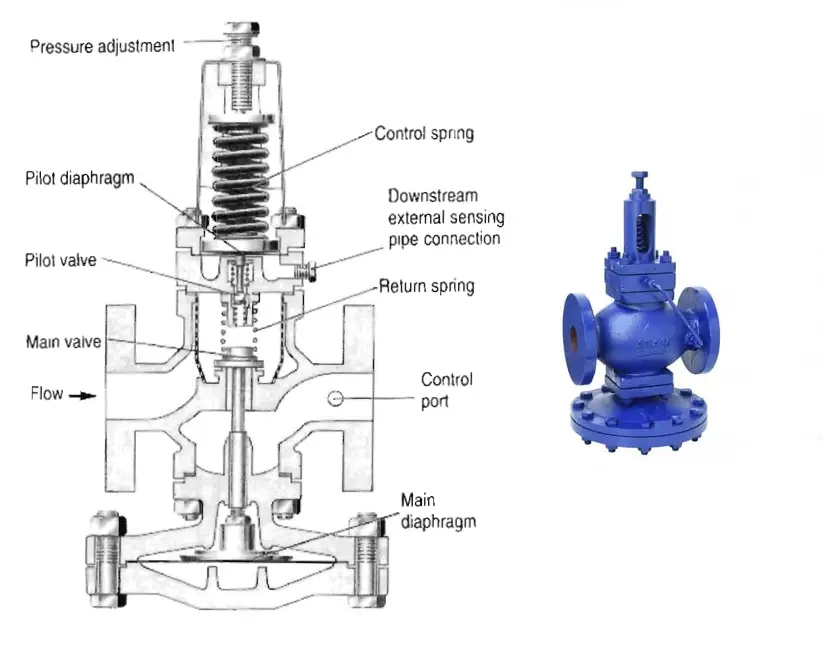
The image in Fig. 1 shows the components of pilot operated pressure-reducing valve.
Fig. 1: Components of a Pilot-operated pressure reducing valve
Applications of Pressure-Reducing Valves
Self-acting pressure-reducing valves are used in the following services:
Air or gas services: Both direct-acting and pilot-operated pressure-reducing valves for air and gas services are used in compressed air systems, power tools, pneumatic control systems, and control valves for industrial gas storage and distribution systems. The selection of the type of pressure-reducing valve for these services is based on the accuracy of control required.
Water services: Pressure-reducing valves find wide application in domestic and industrial water distribution services and fire protection systems. In general, direct-acting pressure-reducing valves are preferred for these services. During high-demand scenarios, maintaining system pressures becomes very difficult. Pressure-reducing valves are used in those lines which can effectively control the pressure downstream to an acceptable limit.
Steam services: The majority of the pressure-reducing valves are used in steam applications involving direct steam supply, steam engines, and turbines.
Other Services: Pressure-reducing valves find their applications in the following:
Bearing lubrication systems in heavy industrial equipment and rolling mills.
In hydraulic presses to control ram pressure.
To control the pressure in fuel-oil systems.
To reduce pressure in sterilizers, humidifiers, unit heaters, and small process equipment
Advantages of Pressure Reducing Valves
The main advantages of a pressure-reducing valve are:
No requirement for an external power source.
Separate measuring elements or feedback controllers are not required.
Simple design with low cost.
High reliability and easy maintainability
External leakage and source of high friction are eliminated by the absence of stem packing.
Fast response
Pressure Reducing Valve vs Pressure Relief Valve
The main differences between a pressure-reducing valve and a pressure-relief valve are
1.0 Pressure-reducing valves maintain almost constant pressure at the downstream side of the valve. So, this valve is used only to maintain or reduce the higher pressure. Whereas pressure relief valves are used to protect equipment and systems from high pressure when the system or equipment pressure exceeds the set limit.
2.0 Pressure-reducing valves operate continuously in the line whereas pressure-relief valves pop up only when the set pressure limit is exceeded.
3.0 In a pressure-reducing valve the pilot line senses the outlet pressure whereas in a pressure-relief valve the pilot line senses the inlet pressure.
4.0 In normal working conditions, the pressure-reducing valve will be in the open position but the pressure-relief valve remains in a closed position.
Reliable fire protection is the requirement for industrial valves in sensitive applications where fire accidents can happen easily. The valves used in the oil and gas, refinery, chemical, and petrochemical industries must guarantee a reliable and safe shut-off in case of fire. Fire-safe design is an important criterion for such industrial valves. The term fire-safe means the ability of the valve to minimize the amount of process lost (leakage) downstream or to the atmosphere after a fire test.
1. What is a Fire-Safe Valve?
Fire-safe valves are specialized valves designed to prevent the escape of fluids and gases in the event of a fire. These valves are engineered to maintain their functionality even under extreme temperatures, ensuring that flammable substances do not leak, thus minimizing the risk of fire spread and explosions.
So, fire-safe valves are various types of valves typically installed in piping systems where the process fluids pose a potential fire hazard. They are designed to ensure a safe and reliable shut-off in the event of a fire.
2. Fire-safe Valve Standards
Industrial valves are not an entity of fire hazards. For valves used in the oil and gas industries, the American Petroleum Institute (API) has developed fire tests. After years of refinement, API 607, ISO 10497, API 6FA, BS 6755, and BS 5146 have been accepted as the standards of fire tests of valves. There are some other standards and procedures like API RP6F, FM 6033, Exxon BP3-14-1, OCMA FSV-1, etc. Using these standards as guidelines, many organizations make their internal procedure for fire-safe valves.
A universally accepted firefighting strategy mentions that if a fire is not beaten in one-half hour, a withdrawal and containment policy is instituted. Structural failures like flange bolt failures, pipe rack collapse, and concrete eruptions will occur. Based on this concept, a fire test duration of one-half hour (30 minutes) has been established.
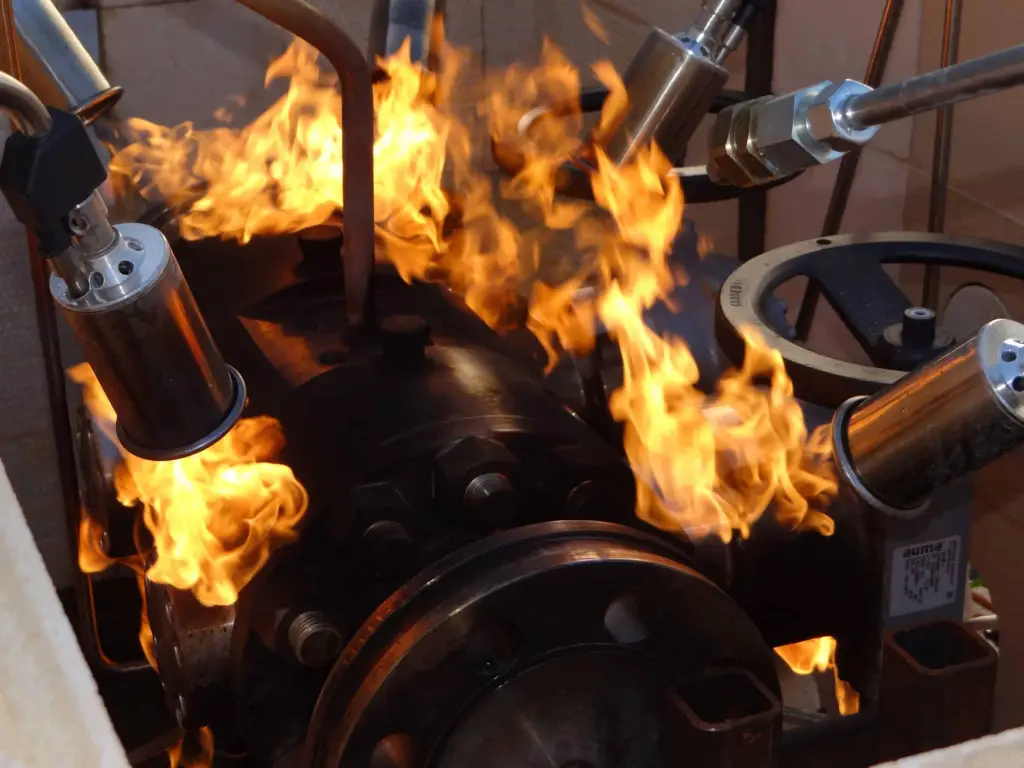
3. Principle of Fire Testing of Valves
The idea behind the fire tests is that any fire-safe valve under pressurized conditions must operate after being burnt at a specified high temperature for a specified period and leakage after burning should be within specified limits. The usual principle of fire testing of valves or fire-safe valve testing is as follows:
The water-filled pressurized closed valve is fully enveloped uniformly in high-temperature flames of around 750 °C to 1000 °C for a period of 30 minutes. When the valve is completely enveloped in fire, exposing the seat and sealing areas to burn temperature, the heat intensity is monitored with thermocouples and calorimeter cubes. During this period, the external and internal leakage past the valve is measured. This leakage should be within acceptable limits. Also, once the valve is cooled after the fire test, the pressure-containing capability of the same valve seats, shell, and seals is tested.
The stem and bore are usually kept in the horizontal position. Check valves are tested in their normal operating position.
The temperature is measured using two thermocouples. One is located 25 mm below the valve under test and the other 25 mm from the upper stem packing box on the horizontal centerline.
The piping to valve end connections for joint leakage are not part of valve fire testing.
4. Fire-Safe Valve Design
In some situations, a valve may need to open or close while exposed to a severe fire. Manufacturers offer two main options for achieving this:
Robust Materials: Fire-safe valves are constructed from strong materials and seals that can withstand high temperatures without sustaining damage.
Fail-Safe Mechanisms:
Pneumatic Actuators: These typically use springs or compressed air to achieve a fail-safe mode. If there is a power failure or loss of air pressure, the actuator is driven to its fail-safe position by the spring or compressed air.
Electric Actuators: Many include a battery backup to ensure they can move to the fail-safe position during a power outage. Some electric actuators may also use a mechanical spring mechanism similar to pneumatic designs.
Manual Operation: Manual valves can be integrated into a larger system with fail-safe features. For instance, an alarm system can alert personnel to operate certain valves manually in the event of a fire.
Temperature Protection: A protective system can prevent the actuator from overheating, which could lead to seal failure or distortion of components. This system aims to keep the actuator within a safe temperature range during a fire, protecting the valve’s parts from extreme heat damage.
4. 1 Design Variations
The fire-safe design of valves can vary by manufacturer. Here are some common features:
Fire-Safe Butterfly Valves: These often feature three sealing layers. They use a soft insert for a tight seal under normal conditions, alongside a metal-to-metal seal that closes securely even if the soft seal is compromised. These seals are typically made from specialized materials like graphite or PTFE (polytetrafluoroethylene), which resist heat, fire, and chemical exposure. They generally operate in temperatures ranging from -73 to 232 °C (-100 to 450 °F) and pressures up to 102 bar (1480 psi), meeting the tight sealing standards of MSS SP-61.
Spring-Driven Actuators: Some fire-safe designs utilize spring-driven actuators that automatically close the valve when a fire is detected.
Floating-Ball Valves: Commonly used in fire-safe designs, these valves feature PTFE seat rings and multiple sealing layers to prevent external leakage. Seals are located between the stem and gland flange, the gland flange and body, and the body and adapter. One layer typically includes an o-ring, while another consists of a graphite gasket. The graphite gasket serves as a backup to prevent leakage if the o-ring is damaged by heat.
5. Selection of Valves for Flammable Services
In the chemical processing and refining industries, choosing valves that can safely handle flammable fluids is crucial. Manufacturers offer specialized designs known as fire-safe valves for this purpose. Selecting the right valve for ensuring shut-off in the event of fire begins with a clear understanding of what “fire-safe” means, along with the standards set by users and independent testing organizations.
It’s important to note that a valve intended for fail-safe operation may not need to perform under fire conditions for many years, and ideally, never at all. Therefore, the selected valve should provide a tight shut-off under normal operating conditions as well as during and after a fire. Reviewing the construction features of various fire-safe valve types will aid in making an informed selection.
According to the Manufacturers Standardization Society, the terms “fire safe” or “fire tested” are not definitive and should not be used without accompanying specifications that outline the requirements. These specifications may include defined test protocols or limitations on valve failure modes. Examples of such limitations include:
Leakage Control: The destruction of elastomeric materials in the valve should not lead to significant pressure-boundary leakage.
Leakage Rates: Any damage to elastomeric materials must not result in leakage exceeding specified rates when the valve is closed.
Pressure Management: External heating of the valve should not cause uncontrolled pressure buildup in the body cavity of a double-seated valve.
Three critical criteria for evaluating fire safety in valves, which are major concerns for testing authorities, are external leakage, internal leakage, and operability after a fire.
Minimal External Leakage: The best valve designs reduce external leakage by eliminating large gasketed joints and utilizing effective stem sealing with fire-resistant materials.
Minimal Internal Leakage: For fire-safe sealing integrity, some valve designs employ metal-to-metal seating before, during, and after exposure to fire, minimizing reliance on complete destruction of primary resilient seals or any supplementary mechanisms to achieve contact.
Continued Operability: A truly fire-safe valve must remain operable even after fire damage. The optimal design prevents heat distortion of the valve body and operating mechanisms caused by thermal and piping stresses during a fire. While some increase in torque may be expected, actuators should be selected with an adequate safety factor to ensure functionality under worst-case scenarios.
6. Types of Valves Used in Fire Safe Service
A fire-safe valve is designed to withstand high temperatures during a fire while providing an acceptable level of shut-off under specific conditions. Due to the extreme heat, these valves are typically constructed from metal. Consequently, gate and globe valves were among the first types recognized as fire-safe, thanks to their metal-to-metal seating. However, because of this seating design, they can leak under normal operation and may experience increased leakage if distorted by heat.
Currently, there are no standardized tests to evaluate the fire-safe capabilities of gate or globe valves. As a result, soft-seated fire-safe valves have become more popular for several reasons:
They provide a tight shut-off during normal operation as well as during and after a fire.
They are cost-effective.
They are easier to automate compared to gate or globe valves.
They are designed and manufactured to meet established fire-safe valve standards.
Today, soft-seated rotary valves, including ball valves, high-performance butterfly valves, and some plug valves, are commonly used. These valves achieve bubble-tight shut-off while also ensuring fire safety by employing two types of seating arrangements.
The first and most common is known as a two-stage seat system. This design requires the complete burn or melt of the resilient seat before achieving metal-to-metal sealing. In the case of a fire-safe ball valve, metal sealing occurs when the floating ball moves downstream to contact a machined surface in the valve body that matches the ball’s contour. However, if a fire is quickly extinguished or conditions prevent complete seat burn, the floating ball may not fully contact the downstream metal seat, leading to excessive internal leakage and undermining the testing standards.
A second system, utilized by some high-performance butterfly valve manufacturers, does not rely on total seat burn. In this design, the resilient seat and metal seat make contact with the disc simultaneously. This ensures that even if the resilient seat is only partially burned, there is still a reliable metal-to-metal contact that provides an established leakage rate.
External leakage is another challenge. The most common leakage occurs past the valve stem once the thrust washer melts, necessitating a secondary metal-to-metal seating arrangement. This is typically achieved by expanding the outer diameter at the stem’s base to contact a machined lip in the valve body. In manually operated valves, this design is effective as long as the handle does not obstruct vertical movement of the stem. For automatically actuated valves, the drive coupling must accommodate this motion.
For valves with a two- or three-piece body design, it’s crucial to pay attention to body seal materials to prevent leakage during a fire. High-performance butterfly valves often feature a rigid disc and stem connection, and the packing material is typically graphite-based to withstand temperatures up to 1300°F (700°C). Many high-performance valves use a one-piece body design to eliminate the risk of body seal leakage.
7. How Testing Houses Define Fire
Users of fire-safe valves often work with in-house or independent testing committees to create fire-safe test standards that meet their specific needs. Here are key factors to consider for fire-safe valve test specifications:
Valve Type: This includes designs with metal-to-metal seating, which can be further divided into:
Continuous Contact Seats: These have constant metal-to-metal contact when closed.
Two-Stage Seats: These rely on secondary mechanisms, like overtravel or pressure, to achieve metal-to-metal contact during a fire.
Stem Position: The position of the valve stem is important for evaluating the severity of a fire test. It can affect how the valve performs under high temperatures, especially with different fluid pressures.
Bore Position: For testing, the bore is often placed horizontally to ensure that the closure element’s weight does not affect the seal, particularly in floating ball valves.
Valve Open or Shut: Testing an open valve is generally more severe. Open valves may sag and not close completely after a fire, leading to leakage.
Test Pressure During Burn: Standards organizations typically set a low-pressure requirement for testing, assuming most valves are not used at maximum pressures. This approach needs to consider good piping practices for safety.
Test Medium: Water is safe and easy to measure but may make it hard to detect leaks. Hydrocarbons, while riskier, provide clearer indicators of leaks due to their viscosity and flammability.
Burn Duration: The test duration should depend on the valve type and size. Smaller valves may completely fail while larger ones might only partially fail, making both types of testing necessary.
Leakage Measurement Timing: Seat leakage is measured during and after the fire in some tests, while others measure leakage only after the fire.
Allowable Leakage: This is critical for safety, especially regarding toxic leaks. Standards like MSS-SP 61 and API 598 set specific leakage rates for new valves.
Operability: Tests may require the valve to open and close multiple times when hot. This ensures the valve functions correctly even after exposure to fire.
Overall Assessment: Despite differences in testing methods, existing tests generally indicate whether a valve is fire-safe. Users may need to combine or modify tests to fit their specific requirements. A key point is that during a fire, a fire-safe valve may shift from having a complete seal to a partially or fully destroyed one. A partial burn test is a better predictor of how a valve will perform in a real fire.
8. API 607 vs API 6FA
The most widely used standards for fire testing of industrial valves are API 607 and API 6FA. Both standards are devised by the API. So, what are the differences?
API 607 provides fire test criteria for quarter-turn valves and other valves with nonmetallic seating under pressure, whereas API 6FA provides the fire testing requirements for API 6A and API 6D valves.API 6FA is applicable for metal seated valves.
9. Fire Safe by Design vs Fire Safe Tested
There are some confusing terms often used related to fire-safe valves. They are:
Fire Safe by Design: A “fire safe by design” valve is designed to make the valve fire-safe. However, the valve hasn’t been tested.
Fire Safe Tested: A “fire safe tested” valve could have been tested. However, the valve has not been approved by a governing third party.
Fire Safe Approved and Certified: The term “fire safe approved and certified” for valves signifies that they have been tested, approved, and certified by a governing third party following the guidelines mentioned in common standards like API 607, API 6FA, ISO 10497, etc.
10. Fire-Safe Ball Valves
For applications involving explosive or fire-risk environments, fire-safe ball valves are produced. These valves are specially designed to limit the spread of fire. The fire-safe ball valves are normally fire-tested to API 607, API 6FA, and BS 6755-Part 2. Fig. 1 below shows a typical fire-safe ball valve diagram.
Fig. 1: Fire-safe Ball Valve
In conclusion, fire-safe valves are critical components in maintaining safety in various industries. Their ability to function under extreme conditions can save lives and protect assets.
FAQ: Fire Safe Valves
1. What are fire-safe valves? Fire-safe valves are specially designed valves that can withstand high temperatures during a fire while ensuring a reliable shut-off to prevent leaks of hazardous fluids.
2. Why are fire-safe valves important? They are crucial for protecting against fire hazards in industries that handle flammable materials. These valves help prevent the escape of toxic or flammable substances during a fire, enhancing safety and minimizing environmental impact.
3. What standards govern fire-safe valves? Fire-safe valves are typically tested according to standards such as API 607 and API 6FA, which outline requirements for fire testing and leakage performance.
4. What materials are used in fire-safe valves? Fire-safe valves are often made from robust materials such as carbon steel, stainless steel, and specialized sealing materials like graphite and PTFE, which can withstand high temperatures and resist thermal degradation.
5. How do fire-safe valves function during a fire? In the event of a fire, fire-safe valves are designed to maintain their integrity. They can operate normally or move to a fail-safe position, depending on the actuator type (pneumatic or electric) and valve design.
6. What types of fire-safe valves are available? Common types include fire-safe butterfly valves, ball valves, and gate valves. Each type has specific features designed to enhance performance under fire conditions.
7. How is leakage tested in fire-safe valves? Leakage is typically tested during and after exposure to fire. The tests assess both external and internal leakage rates to ensure compliance with established standards.
8. Can fire-safe valves be used in all applications? While they are suitable for many applications involving flammable materials, it’s essential to choose the right type of fire-safe valve based on the specific requirements of the process, including pressure, temperature, and fluid characteristics.
9. What maintenance is required for fire-safe valves? Regular inspections and maintenance are necessary to ensure optimal performance. This includes checking seals, actuators, and overall valve integrity, especially after exposure to extreme conditions.
10. How do I choose the right fire-safe valve for my application? Consider factors such as the type of fluid being handled, operating temperature and pressure, leakage requirements, and compliance with industry standards. Consulting with manufacturers or industry experts can also help in making an informed decision.