A breather valve is a special type of pressure and vacuum relief valve used to protect atmospheric and low-pressure tanks & vessels in which fluids are filled and drawn at a high flow rate. Proper installation of breather valves can prevent tank explosions due to overpressure and collapse due to vacuum conditions. The breather valve does not release the vapor until the tank pre-set pressure is reached. So, it can be used to reduce evaporation loss. It balances the fluctuations in pressure & vacuum by eliminating excessive pressure or vacuum and provides increased fire protection and safety.
Using weighted pallets or springs in the breather valves, the pressure and vacuum protection levels can be controlled. It is normal practice to combine both pallet and spring systems in one unit to provide the required Pressure/Vacuum settings. In a breather valve, the pressure settings require a spring section, whilst the vacuum settings use the pallet method.
Working of a Breather Valve
A breathing valve consists of an in-breathing valve and an out-breathing valve. They are arranged side by side or overlapped. When the tank pressure becomes equal to atmospheric pressure, the disc and seat of the pressure valve and the vacuum valve work together making the seat tight without leakage. When the pressure or vacuum increases, the disc of the breather valves opens and retains a good seal because of the “adsorption” effect on the side of the seat.
When the tank pressure increases and reaches its design values, the pressure valve opens discharging the gas in the tank into the outside atmosphere through the side of the vent valve known as the pressure valve. At this time, the vacuum valve is closed due to the positive pressure in the tank. On the other hand, during the out-breathing process due to tank loading and evaporation of liquid due to higher atmosphere temperature, the vacuum valve opens due to the positive pressure of atmospheric pressure. The external gas enters the tank through the suction valve known as the vacuum valve. At this point, the pressure valve closes. Both the pressure valve and the vacuum valve do not simultaneously open at any time. The inhaling and exhaling process stops when the pressure or vacuum in the tank drops to normal and the pressure and vacuum valves close.
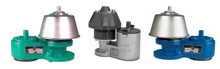
Typical Breather Valves
Types of Breather Valves
Breather valves can be categorized into the following groups:
Pressure and vacuum relief valve: To prevent overpressure or vacuum conditions, the composite pressure and vacuum relief valve are used. Two independent units one to control pressure and the other to control vacuum can also be manufactured and procured as necessary.
Pilot-operated relief valve: To protect from low-pressure or vacuum situations, the pilot-operated relief valves provide safe, accurate, and dependable protection.
Air-operated relief valve: To reduce evaporation loss, highly efficient air-operated valves are used.
Emergency vent valves: For fire or emergency temperature conditions, the emergency vent valve maintains the positive pressure in the tank within allowable design parameters.
Gauge Hatch: Similar to emergency vent valves to carry out manual measurement of tank level with a metallic tape where conventional float and tape type-level instrument is out of action.
Tank Blanketing Valve: To maintain the constant pressure in the vapor space of the storage tank when the tank is under unloading mode or vapor under condensation due to low ambient temperature, Tank blanketing valves are used.
Functions of a Breather Valve
The main functions of a breather valve is:
reducing the vapor loss from the storage tank
preventing the vacuum and pressure from exceeding the tank design limits.
preventing flammable conditions.
protecting the tank contents from moisture intrusion.
Common Standards for Breather Valve
Common standards that govern the design and selection of breather valves are
DIN EN 14595: Tank for the transport of dangerous goods-service equipment for tanks-pressure and vacuum breather vent.
API 2000: Venting of Atmospheric and Low-Pressure Storage Tanks.
API 2521: Use of Pressure-Vacuum Vent Valves for Atmospheric Loss
API 2513: Evaporation loss in the Petroleum Industry-Causes and Control
Advantages of Breather Valve
The main advantages that the application of breather valves serves are
Content protection
Fire hazard prevention
Explosion prevention.
Reduction of corrosion and emission.
Low maintenance.
Safe Pump operation.
Installing Breather Valves
The breather valve must be mounted at the highest point on the top of the tank to reduce evaporation losses and other exhausts. Also, it will ensure the most direct and maximum access to the breather valve. Usually, the Breather Valve is mounted on a nozzle opening of a fixed roof atmospheric storage tank. As the fixed roof atmospheric storage tanks do not contain any controlled openings, there are high chances of rupture under increasing pressure caused by pumping liquid into the tank or as a result of vapor pressure changes caused by severe thermal changes. On the contrary, the tank can implode during the pumping out procedure or thermal changes. When the liquid level lowers, the vapor space pressure is decreased to below atmospheric pressure. This vacuum condition is alleviated using the breather valve.
Parameters Affecting breather valve performance
The proper working of a breather valve depends on the following five factors:
Pressure and Vacuum Settings
Temperature Variations
Temperature vs Humidity
Number of Airlifts, and
Amount of Desiccant
Selection of Breather Valves
The selected breather valve must be able to reduce moisture intrusion in the tank. These valves must protect the tank from a vacuum and excessive pressure. Hence, the breather valve needs to be sealed except during the airlift and in extreme temperature conditions. Certain tank parameters must be known for the proper selection of a breather valve. These are
The maximum pressure and vacuum condition that the tank is able to withstand.
Tank volume.
How quickly the pressure change can take place.
The temperature variation during the storage.
Relative humidity and temperature of the storage area.
Materials for Breather Valves
Breather valves are usually manufactured of the following materials:
Carbon Steel
Aluminum
Stainless Steel
Cast Iron
However, breather valves can be manufactured of any material that is required based on service conditions.
Fasteners are mechanical devices to rigidly affix or join two or more mechanical items. Fasteners are widely used for mechanical joints requiring dismantling as they usually create non-permanent joints. Mechanical fasteners or fastening hardware are extensively used in various industries including Automobiles, Construction, Aircraft, Agriculture, Machinery and Appliances, Infrastructure, etc. In this article, we will learn the definition of a fastener, Its types, materials, applications, and relevant codes and standards.
What is a Fastener?
A fastener is a broad range of mechanical tools/elements used to hold two or more objects together as a rigid attachment. Fasteners allow for the separation or dismantling of the pieces without suffering any damage. However, they can be used as permanent joints as well. Screws, nuts, bolts, nails, washers, etc are different types of fasteners.
Types of Fasteners
There are different types of fasteners that are used in industrial applications. The most common types of mechanical fasteners are:
Nuts and bolts are one of the most common types of fasteners available for industrial use. They work together in tandem and hold two or more components together. The bolt is inserted through the bolt holes between the components and then the nut is fastened on the other end. There are various types of nuts and bolts as mentioned below.
Types of Nuts:
Nuts have internal threads and are always used with a mating bolt. The most popular types of nuts are:
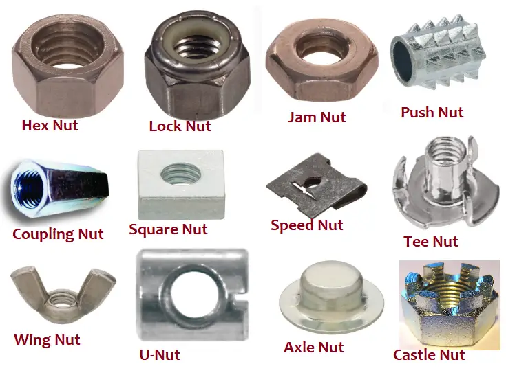
Hex Nuts: The most common variety of nuts, Hex Nuts consist of a hex shape (six-sided) with internal threads. They can be easily tightened or loosen with a wrench accessing from any angle.
Coupling Nuts: They are also hex-shaped nuts. This hollow-threaded fastener joins two male threads together and is also known as an extension nut. They are widely used for installing plumbing pipes.
Lock Nuts: Locknuts are specially designed fasteners to prevent loosening due to vibrations. Also known as prevailing torque nuts, lock nuts find uses in automotive and washing machines where vibration problems have the tendency to loosen parts.
Square Nuts: Feature a square shape, square nuts are the oldest type of nuts with four sides. They are the best for the greater surface area making the fastener stronger and reducing damage from rough edges. Usually, square nuts are used in furniture and metal channel applications.
Fig. 1: Different Types of Nuts
Flange Nuts: Having a wide, serrated flange on one end, flange nuts serve a similar function as a washer but it does not provide any added movement. They are also known as Tee nuts.
Wing Nuts: Having two projected pieces, wing nuts can be easily loosened or tightened using hands without tools. This type of fastener is good for applications requiring frequent tightening and loosening. Click here to learn more about wing nuts.
Slotted Nuts: In slotted nuts, sections are cut out to create a locking mechanism with the help of a cotter ping. U-Nuts: Reliable and strong, U-nuts are made from one piece of rolled thread. They are used to hold metal sheet panels together.
Speed Nuts: Speed nuts have two metal pieces that work as one. Also known as sheet metal nuts, speed nuts do the job of both a nut and a locking washer.
Push Nuts: Push nuts can distribute loads easily that reduce surface stresses. They are installed with a special nut driver and used to secure unthreaded bolts and other fasteners.
Jam Nuts: Jam nut is small size nut that is half as tall as hex nuts. They are widely used where space has limitations to use hex nuts. They can easily be fastened onto a bolt without applying torque or force.
Axle Nuts: Also known as cap nuts or dome nuts, axle nuts hide the bolt edges and provide a seamless appearance. It provides a nice surface finish and finds use in electrical panels, stereo cabinets, etc.
Castle Nuts: Castle nuts have notches at one end through which a pin can be inserted to fix the nut’s position. They are used when the torque requirements are low.
Some other types of nuts are
Rivet Nuts
Weld Nuts
Barrel Nuts
Shear Nuts
Tri-Groove Nuts
Keps-K Lock Nuts
Knurled Thumb Nuts
Wheel Nuts, etc
Types of Bolts
Many different types of bolts are available in the market. The most common types of bolts that are used for industrial applications are:
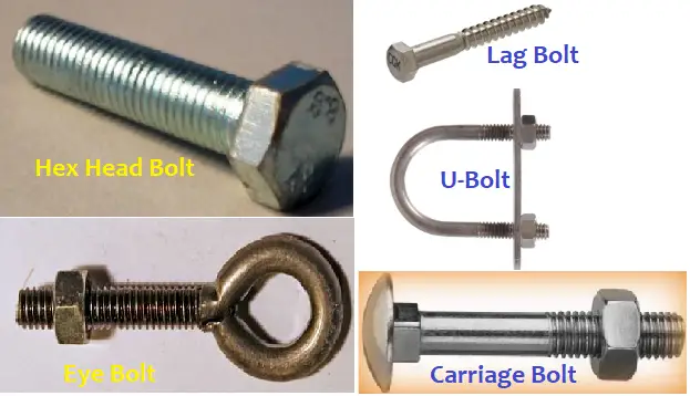
Carriage Bolts: Having domed or countersunk heads, Carriage bolts use a square component under the head to keep the bolt from moving (pulling through) while tightening the nut. Carriage bolts are self-locking bolts and are usually used to attach metals to wood.
Hex Bolts: They have six-sided heads with machine threads extended halfway or up to the bolt head. Hex bolts find wide construction and machinery applications as they can be easily tightened using a wrench. Also popular as hex cap screws, hex bolts work with a tapped hole or a nut.
U-Bolts: U-bolts are shaped like the letter “U” and have screw heads on both ends. The bent section of the U-bolt is unthreaded. They are extensively used in piping, plumbing, and HVAC works to secure the position of pipes and tubes without making any holes in them.
Fig. 2: Different Types of Bolts
Eye-Bolts: Eye bolts are threaded on one end and a loop at the other.
Lag Bolts: These bolts are used independently without a nut. Extremely sturdy and tough Lag bolts can handle a lot of weight. They are used for heavy-duty jobs like installing frames, framing lumber, etc.
Flange Bolts: For even distribution of the loads, Flange Bolts include a circular flange beneath the head.
Allen Bolts: Also known as Socket head bolts, Allen bolts have a hexagonal socket for use with Allen wrenches. These types of fasteners need less space.
There are a few other variations of bolts like:
Plow bolts: for heavy-duty applications, such as heavy equipment, with non-protruding heads.
Square-head bolts: having square heads that offer an easier grip for wrenches.
Peta bolts with 5-sided heads.
Double-end bolts resembling a threaded rod.
Shoulder bolts or Stripper bolts.
Fasteners-Washers
Sometimes washers are added in between nuts and bolts to distribute the fastener’s load evenly over the material surface. A washer is a flat circular disc with an opening in the center. Washers can be metallic or can be made from non-metals. Other main purposes of washers are:
Isolation of Components
Reduction of leakage
Alleviation of friction, and
Prevention of loosening during vibration.
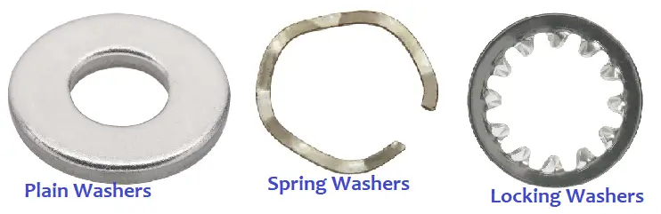
Fig. 3: Types of Washers
Some common types of washers are:
Plain Washers: Plain washers are used for load distribution and isolation purposes. Plain washers can be of various types like:
Round and thin Flat Washers for general use.
Torque Washers for use in woodworking projects.
Fender Washer used in car fenders.
Finishing Washers used with countersank screws, and
C-washers
Spring Washers: These types of fasteners act like a spring as they develop axial flexibility to make the joint more elastic. This can avoid unintended loosening during vibration. The main types of Spring Washers are:
Belleville Washer
Crescent Washer
Dome Spring Washers, and
Wave Spring Washers
Lock Washers: This type of washer uses various mechanisms to prevent nuts, screws, and bolts from loosening. Lock washers are much better than spring washers and can be of the following types:
External tooth lock washer
Internal tooth lock washer
Split lock washer, and
Tab washer
Beveled Washers: These washers add stability when attaching unparallel surfaces.
Structural Washers: Usually thicker, Structural washers are used in heavy-duty applications.
Fasteners-Screws
Screw fasteners are the most versatile type of fasteners. It’s very simple to use. One needs to drill a pilot hole in a material and then using a screwdriver the screw can be easily installed in place. They generally have male threads that start from the tip. Screws are usually self-threading and create the thread during installation.
They come in various types and sizes like:
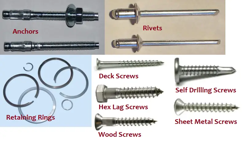
Self-Drilling Screws: Also popular as self-tapping screws, self-drilling screws create the required internal thread while installing it. It contains a fully threaded shaft.
Machine Screws: These types of fasteners are most widely used for machinery applications. It comes in a variety of tip shapes and heads with a slotted socket on the head to tighten it. They are of uniform thickness and don’t taper off at the bottom.
Sheet Metal Screws: With an extremely sharp tip, sheet metal screws are used to fasten two metals together. They have a flat or rounded head.
Other types of Screws are:
Deck screws having a self-tapping design.
Wood screw having coarse thread and tapered head.
Grub Screws without a head used to prevent rotation or movement between two parts.
Masonry screws having flat tips and hex-head designs.
Countersunk screw
Hex lag screw
MDF screws
Drywall screws
Fig. 4: Various Types of Fasteners
Nails as Mechanical Fasteners
Nails are the oldest type of fasteners used since ancient times. It is still used as an everyday household item. Nails do not have threads and usually have less power than screws. The most widely used types of nails are:
Common nails having a thicker shank.
Box nails with a diamond point tip.
Roofing nails with a wide head.
Framing nails are specially designed for flush installation and easy concealment.
Brad nails for easily blending into wood trims.
Flooring nails for use with flooring materials.
Drywall nails for reduced slippage.
Finishing nails with small flatheads.
Anchors as Industrial Fasteners
Anchors are a particular type of fastener that is used to connect something to a material like concrete or drywall. They embed themselves in the material and hold the object in place. Various types of anchors are used to serve different types of functions. Some common types of well-known anchors are:
Internally threaded anchors
Externally threaded anchors
Acoustical wedge anchors
Masonry screw and pin anchors
Bonded anchors
Screw anchors
Double expansion shield anchors
Hollow wall anchors
Drop-in anchors
Sleeve anchors
Plastic anchors
Drive anchors
Mechanical Fasteners-Rivets
Rivets create a permanent joint between objects and are hence known as permanent fasteners. Consisting of a cylindrical shaft with a head on one end and a tail on the other, Rivets offer great support against shearing forces. This type of fastener is lightweight and remarkably durable. A unique tool popular as a rivet gun is required to install rivets. Rivets can not be reused after removal. Some common types of rivets include:
Blind rivets
Pop rivets (Closed-end, Open end, Countersunk)
Semi-tubular rivets
Large flange rivet
Solid rivets
Tri-fold rivet
Split rivets
Drive rivets
Structural rivets
Colored rivets
Multi-grip rivets.
Fastener types-Pins
Pins are unthreaded mechanical fasteners usually inserted through preformed holes. The most common types of pins for industrial usage are:
Dowel pin
Slotted pin
Coiled pin
Roll pin
Grooved pin
Split pin
Wedge pin or tapered pin, known as cotter.
Retaining Rings
Retaining rings are a non-permanent type of metallic fasteners used to hold multiple parts together. It usually consists of spiral, semi-circular metal pieces. Retaining rings are employed in many applications in machinery and housing components.
The various types of retaining rings that are found are:
Constant section retaining ring
Snap retaining ring
Tapered section retaining ring
Axially assembled retaining rings
Spiral retaining ring
Radially assembled retaining ring
Circular push-on
Bowed-E retaining rings
External shaft retaining rings
Self-locking retaining rings.
Inserts
Inserts perform a range of tasks as mechanical fasteners. They are usually used for reinforcing joints, fixing eroded internal threads, used as keys in rotating machinery, or fastening anchor bolts to hanging pipelines. Inserts are available in different forms like:
Keys in shaft key-ways
Threaded rod
Unthreaded rod
Helical threaded inserts
Keystock
Other Types of Fasteners
There are many other types of fasteners that are used. Some of those fasteners are
Clamps
Staples
Straps
Hooks and Eyes
Twist ties, etc
Fastener Materials
Fasteners are made of a variety of materials. Proper selection of a fastener material should be based on the working environment, weight, expected life, reusability, magnetic properties, and reusability. Common materials that are used for manufacturing fasteners are:
Steel
Brass and Bronze
Copper
Nickel
Aluminum
Stainless Steel
Inconel
Monel
Titanium
Nylon and Plastics
Fastener Codes and Standards
Widely used standards for industrial fasteners are:
ASME B18.6.3 for Machine Screws, Tapping Screws, and Metallic Drive Screws (Inch Series)
ANSI B18.6.1 for Wood Screws (Inch Series)
ASME B18.6.2 for Slotted Head Cap Screws, Square Head Set Screws, And Slotted Headless Set Screws (Inch Series)
ASME B18.24 for Part Identifying Number (PIN) Code System Standard for B18 Fastener Products
ASTM-A31 for Steel Rivets and Bars for Rivets, Pressure Vessels
ASTM-A320 for Alloy Steel Bolting Materials for Low-Temperature Service
ASTM-A193 for Alloy-Steel and Stainless Steel Bolting Materials for High-Temperature Service
ASTM-A194 for Carbon and Alloy Steel Nut for Bolts for High-Pressure and High-Temperature Service
ASTM-A307 for Steel Bolts and Studs, 60,000 PSI Tensile Strength
SAE-J78 for Steel Self-Drilling Screws
SAE-J81 for Thread Rolling Screws
SAE-J82 for Mechanical and Quality Requirements for Machine Screws
SAE-J238 for Nut and Conical Spring Washer Assemblies
SAE-J482 for Hexagon High Nuts
SAE-J492 for Rivets and Riveting
SAE-J493 for Rod Ends and Clevis Pins
SAE-J773 for Conical Spring Washers
SAE-J891 for Spring Nuts
SAE-J892 for Push-On Spring Nuts, Inch Series- General Specifications
ANSI-B1.1 for Unified Inch Screw Threads (UN and UNR) Thread Form
ANSI-B18.1.1for Small Solid Rivet
ASME B18.18 for Quality Assurance For Fasteners
ANSI-B18.1.2 for Large Rivets
ANSI-B18.22.1 for Plain Washers
ASME B18.3 for Socket Cap, Shoulder, Set Screws, and Hex Keys (Inch Series)
ISO 2339, ISO 7089, ISO 7090, ISO 2340
DIN 125, DIN 126, DIN 1444
BS4464B
Fasteners Selection Criteria
A variety of factors need to be considered during fastener selection for industrial applications. Some of them are
Material of construction (stainless steel, carbon steel, or alloy steel).
Materials to be joined.
Environment, including temperature, water exposure, and potentially corrosive elements.
Installation process.
Re-usability.
Weight restrictions.
The applied load on the fastener.
The stiffness of the fastener.
Special process conditions (special coatings or plating).
What’s new in ASME B31.3-2020? ASME B31.3 2020 vs 2018
Hopefully, all of you are aware that the latest edition of the process piping bible ASME B31.3-2020, which revised the 2018 edition of the same code is issued on the 18th of June, 2021. Similar to earlier editions, this code also will become universally effective 6 months after the date of issuance means from 17th December 2021 onwards. Similar to the earlier new releases, ASME B31.3-2020 also provides many clarifications, updates, and changes. In this article, I will list down 10 such major changes that ASME B31.3-2020 will bring into effect with respect to ASME B31.3-2018.
Changes with respect to Units of Measurement
Additional clause 300.1.4– Units of Measure added stating that either SI or U.S. Customary units should be independently used as the stated values in the ASME B31.3-2020 are not exact equivalents. If It is required to convert from one system of units to another, conversion should be made by rounding the values to the number of significant digits of implied precision in the starting value but not less than four significant digits for use in calculations.
The earlier clause in the 2018 edition “300.1.4- Rounding” has been renumbered as clause 300.1.5 in ASME B31.3-2020.
Changes with respect to the Flexibility Factor and Stress Intensification Factor
Appendix D that was providing the equations for the Flexibility Factor and Stress Intensification Factors of Table 300.4 Status of Appendices in B31.3 has been deleted from ASME B31.3-2020 edition. In the absence of more directly applicable data, the flexibility factor, k, and stress intensification factor, i, shown in ASME B31J shall be used for flexibility calculations described in para. 319.4. Flexibility factors and stress intensification factors for branch connections are defined for in-plane, out-plane, and torsion moments on both the run and branch legs. Branch leg calculations shall use the appropriate branch factor (i.e., kib, kob, ktb, iib, iob, and itb), and run leg calculations shall use the appropriate run factor (i.e., kir, kor, ktr, iir, ior, and itr).
This is the most significant change for piping stress engineers. Now using B31J or FEA will be mandatory. Earlier, the same SIFs were used in the stress analysis programs for headers and branches which in some cases becomes too conservative. Now that problem will be resolved.
Experimental Stress Analysis for Unlisted Components
As per clause 304.7.2 sub-para (b) of the latest edition of ASME B31.3 2020, for experimental stress analysis of unlisted components following the equations from ASME BPVC, Section VIII, Division 2, Annex 5-F, the basic allowable stress from Table A-1 (or A-1M) of B31.3-2020 shall be used as allowable stress, S.
In a similar way, for proof testing of unlisted components following the equations from ASME B16.9, MSS SP-97, or ASME BPVC, Sec VIII, Division 1, UG-101, the basic allowable stress from Table A-1 or Table A-1M shall be used in place of the allowable stresses, S and S2, in Division 1 where applicable.
Bending Stress Calculation for Header and Branch
Equations 19 and 20 for calculating bending stresses in header and branch as was there in clause 319.4.4 sub-paragraph (c) have been deleted in ASME B31.3 2020 contrary to the ASME B31.3-2018. Similarly, equation 23-b2 has also been deleted.
Impact test requirement for Weld Metals
The impact test requirement criteria for Weld Metal of the welding procedure qualification test coupon has been changed in table 323.2.2 of ASME B31.3-2020. In code B31.3-2018, the impact test was required for design minimum temperature<-29 Deg C. However, the latest edition of B31.3 requires an impact test for design minimum temperature below -18 Deg C.
Additional Standards
The following additional standards are added in Table 326.1 of ASME B31.3-2020 with respect to the earlier revision B31.3-2018.
Standards ASTM D3309, D2310, D2447, and ASTM F1974 have been deleted from Table A326.1 Component standards for non-metallic piping systems.
Use of ASME B31P
Clause 330.1 in ASME B31.3-2020 provides permission to use preheating rules from ASME B31P as an alternative to general preheat requirements. Additionally, the process and temperature control methods specified in ASME B31P are recommended for heat treatment purposes.
Consideration of Frictional Clamping Force for Supporting Non-Metallic Piping
For supporting non-metallic piping systems, ASME B31.3-2020 prohibits to use of frictional forces from clamping pressure as an anchor mechanism unless the support/anchor is specifically recommended for this purpose by the manufacturer. Positive stops like shear collars can be used as axial restraints. There was no such prohibition in ASME B31.3-2018.
Shear and Bearing Allowable for High-Pressure Piping System
The allowable stress definition for shear and bearing in the case of high-pressure piping has been revised in ASME B31.3-2020. Now the allowable stress in shear should be 0.57 times Syt (in place of 0.8 times as provided in B31.3-2018). The allowable stress in bearing shall be 1.0 times Syt (in place of 1.6 times as provided in B31.3-2018).
Also, the basis for allowable stresses for other materials (other than bolting materials) for the high-pressure piping system has been modified with respect to the earlier edition. Refer to clause K302.3.2 sub-paragraph (b), (c), and (d) for details.
The majority of the changes or revisions in ASME B31.3-2020 have been made for High-Pressure and High-purity piping systems.
Welding stainless steel is the principal joining method employed during the fabrication of stainless steel products and components. Because of its excellent corrosion resistance, and elevated and cryogenic temperature properties, stainless steel is one of the widely used engineering materials. Stainless is extensively used in the oil and gas, chemical, petrochemical, power plant, food, and pharmaceutical industries.
Stainless Steel Welding Processes
Welding of stainless steel is generally performed by two basic methods: Fusion Welding and Resistance Welding.
Welding Stainless Steel by Fusion Welding
Fusion welding of stainless steel generates heat by an electric arc struck between the metallic electrode and the stainless steel material. Four widely used principal processes that are used for fusion welding of stainless steels are:
SMAW (Shielded Metal Arc Welding)
GTAW (Gas Tungsten Arc Welding)
GMAW (Gas Metal Arc Welding)
SAW (Submerged Arc Welding)
There are some other fusion weldings methods like electron beam, laser, and plasma arc welding. Note that, To preserve optimum corrosion resistance and mechanical properties in the joint, the weld zone must be protected from the atmosphere by a gas, vacuum, or slag.
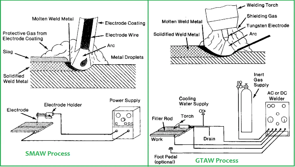
Welding Stainless Steel with SMAW:
SMAW, being a fast and versatile process, is very popular for stainless steel welding. The manual welding method uses a solid electrode wire with an extruded baked-on coating material. One end of the electrode that is held in a spring-loaded electrode holder is bare. The operator holds the electrode at an angle at a minimum distance from the base metal to maintain the arc and moves it along the joint.
The alloy composition of the SS material decides the selection of electrodes for SMAW. Depending on the type of power supply and welding types, the coatings of electrodes are usually lime-based or titania-based materials. The coating creates a gas envelope that protects the molten metal from air contact. Refer to Fig. 1 for a basic representation of the SMAW stainless steel welding process.
Welding Stainless Steel with GTAW:
Also known as Tungsten Inert Gas Welding or TIG welding, the welding of stainless steel by GTAW uses Argon or any other inert gas to protect the welding zone from atmospheric contact. An intense electric arc generated between the non-consumable tungsten electrode and the SS workpiece creates the necessary heat for welding. In case filler metal is required, a bare welding rod is fed into the weld zone to melt with the base metal.
GTAW is widely used for welding stainless steel pipes, and joining tubes to tube sheets in shell and tube heat exchangers. There are two variations for GTAW for stainless steel welding to increase welding speed and get higher deposition rates.
In the first variation, known as hot-wire GTAW, an automated process is used and the filler wire is heated by resistance heating.
Pulsed-arc GTAW is another variation where a pulsing arc is used that controls the molten weld puddle to increase penetration.
The following figure (Fig. 1) shows a typical representation of welding stainless steel with TIG.
Fig. 1: Stainless Steel Welding Process-SMAW and GTAW
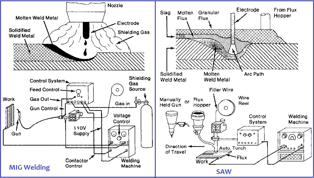
Welding Stainless Steel with GMAW:
Also widely popular as MIG welding, the gas metal arc welding of GMAW is a gas-shielded arc welding process using a consumable electrode that melts in a gas atmosphere. Refer to Fig. 2, which schematically shows the basic equipment like a torch, supply of shielding gas, DC power supply, and control for wire feed speed through the torch. The coiled form electrode filler metal is mechanically driven into the welding zone. Depending on the method of metal transfer, three variations of the GMAW process are found. They are:
Spray Transfer
Short-circuiting transfer, and
Pulsed-type transfer.
The spray transfer or free flight transfer is characterized by a hot arc and fluid puddle. A short-circuiting transfer that is effective for welding thin stainless steel material utilizes small diameter wire (<0.045 inches). The pulsed-arc welding is characterized by a controlled free-flight metal drop rate of 60 drops per second at a lower current density.
Welding Stainless Steel with SAW:
SAW or Submerged Arc welding is a welding method where the heat for fusing the metal is generated by an electric current between the welding wire and the stainless steel workpiece. A layer of mineral flux composition covers the arc, the workpiece weld area, and the welding wire tip. No visible arc, spark, spatter, or smoke is found in this welding method and hence the name submerged arc welding. Refer to Fig. 2, which represents the SAW method schematically.
Fig. 2: Welding of Stainless Steel-MIG & SAW
Welding Stainless Steel by Resistance Welding
One of the most economical and popular methods of joining stainless steel is by electrical resistance welding where heat is produced by the resistance to the flow of the electric current through the parts to be welded. For the mass volume of repetitive works, resistance welding for stainless steel products is particularly suitable. The widely used resistance welding processes for stainless steel welding are:
Spot Welding
Seam Welding
Projection Welding
Butt Welding
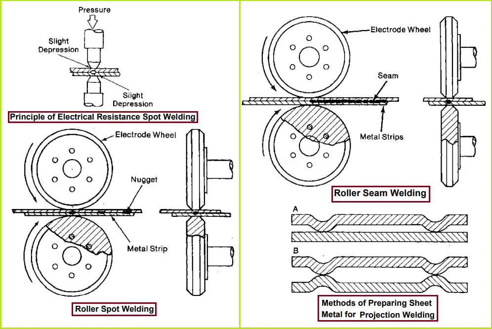
Welding of Stainless Steel using Spot Welding:
In spot welding of stainless steel, coalescence is produced by the heat generated from electric resistance and pressure on the electrodes. The contour of the electrodes limits the shape and size of the welds. The process uses two water-cooled electrodes or wheels which are brought together with the work parts using a mechanical force by foot, air, hydraulic, or motor-operated cam. The welding cycle consists of squeeze time, weld heat time, hold time, and off time. The parameters that affect the welding process are:
A typical process of spot welding is shown in Fig. 3.
Fig. 3: Welding of Stainless Steel-Spot Welding, Seam Welding, and Projection Welding
Welding of stainless steel by Seam Welding:
In the seam welding of stainless steel, circular electrodes (copper-based alloy) are used. A series of overlapping spot welds are progressively made by the rotating circular electrodes (Refer to Fig. 3) which supply the current as well as the pressure to hold the work parts. To get proper weld spacing, the electrode speed and current off-time must be adjusted. Usually, three types of seam welding machines are used:
Circular
Longitudinal, and
Universal
Welding of stainless steel with Projection Welding:
Projection welding is best suited for heavy-gauge stainless steel workpieces. Localized welding is performed at predetermined points by projections, embossments, or intersections. At these projections, heat is concentrated and can be made in one or both pieces as shown in Fig. 3. Projection welding can be performed in almost all stainless steel.
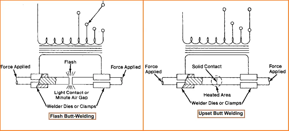
Stainless Steel Welding by Butt Welding Process:
The butt welding process can be grouped into two classes; Flash Welding and upset Welding.
Flash Welding:
In the flash welding process, the work parts initiate a flashing action from the current delivered through the clamped electrodes. The basic sequence of flash welding of stainless steel is:
load machine
clamp workpiece
apply weld current
establish flash by contacting parts
flashing
apply upset force
interrupt current
unclamp workpiece
unload and
return platen.
Flash welding machines are manual, semi-automatic, or fully automatic and can perform various additional operations like pre and post-heating, clamping, shearing, flash trimming, etc. All types of stainless steel can be welded using flash welding.
Fig. 4: Butt Welding of Stainless Steel
The alignment of the parts to be welded is very important so that heat is generated over the entire surface.
Upset Welding:
In the upset welding process, no flash occurs. The coalescence is produced over the entire area by the heat generated from the resistance of the electric current flow through the contact area of the abutting surfaces. The applied force is maintained throughout the heating period. The joining surfaces are brought together under pressure and the current is applied until the correct upset takes place and then the current is interrupted.
The non-heat-treatable stainless steels are easily weldable by this process. Continuous tube mills use this process quite extensively.
Other forms of resistance welding are high-frequency resistance welding, percussion welding, etc.
Welding of Stainless Steel Pipes
The selection of welding method for joining stainless steel pipes is dependent on:
TIG is widely used for stainless steel pipes of 4 inches and smaller sizes. Whereas for large-diameter pipes fully automatic methods are used.
Welding Courses Online
When developing in-depth knowledge about the welding processes and techniques, then the following online welding courses will surely serve the purpose:
Nitriding is a type of heat treatment process to create a case-hardened surface by diffusing Nitrogen. The most common applications of the nitriding process are valve parts, gears, forging dies, crankshafts, extrusion dies, camshafts, firearm components, bearings, textile machinery, aircraft components, turbine generation systems, plastic mold tools, etc. The material widely used for the nitriding treatment process are low-alloy steels, aluminum, molybdenum, and titanium. Depending on the case depth, the nitriding process can take 4 to 60 hours.
Developed early in 1900, the nitriding process is widely used in many industrial applications. During nitriding, no phase change occurs. It is one of the simplest case-hardening processes.
What are the Purposes of Nitriding?
The main purposes of nitriding treatment are:
To get high hardness on the surface. Hardness achieved in nitriding is usually higher than carburizing method.
Also, the nitriding process helps in reducing notch sensitivity. It is a diffusion-related surface treatment process that causes very small volumetric changes. Nitriding treatment can significantly improve properties like fatigue strength, resistance to wear, corrosion resistance, friction, and hardness.
What is the Principle of Nitriding?
Nitriding is a thermochemical treatment process to enrich the surface with nitrogen for the purpose of increasing the surface’s hardness. The process is based on the low solubility of nitrogen in the ferritic crystal structure to promote the precipitation of iron nitrides or alloy nitrides. The connecting nitriding is connected to a diffusion zone where precipitated nitrides are evenly diffused in the steel matrix. The usual nitriding temperature range is 350°C to 590°C. With a decrease in temperature, the nitriding time to reach a given depth increases. The depth of nitriding hardness may reach 500 μm with maximum hardness levels of > 1000 HV.
The nitriding layer formation occurs in the following steps:
adsorption of nitrogen atoms on the surface of the component,
absorption of nitrogen atoms by the component surface, and
diffusion of the nitrogen atoms along the grain boundaries and within the grains.
What are the Types of Nitriding?
There are three types of nitriding processes that are commonly used in industries. They are:
Gas Nitriding,
Plasma Nitriding, and
Salt-bath Nitriding.
What is Gas Nitriding?
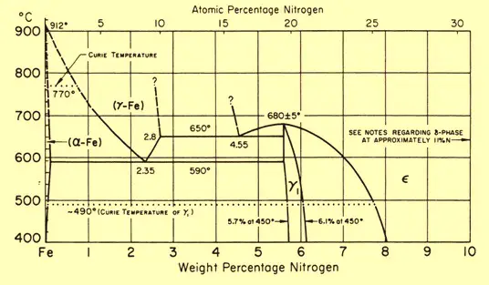
In the gas nitriding process, the metal is heated to a suitable temperature (5000C to 5750C for Steel) and held in contact with a nitrogenous gas, usually ammonia. This is why the process is sometimes known as ammonia nitriding. When ammonia comes into contact with the heated steel, it breaks down into hydrogen and nitrogen. This nitrogen then diffuses onto the metal surface and creates a nitride layer. Depending on the temperature the solubility of nitrogen into iron varies as can be seen from the attached iron-nitrogen equilibrium diagram in Fig. 1.
Fig. 1: Iron Nitrogen Equilibrium diagram
The effectiveness of the gas nitriding process depends on various factors like
Gas Flow
Temperature
Time
Gas activity control
Process control
Process chamber maintenance, etc
What are the Advantages and Disadvantages of Gas Nitriding?
The main advantages of gas nitriding over other types of nitriding treatment are:
Possibility of larger batch sizes (limited by the furnace size and gas flow)
An all-around nitriding effect is achieved.
Relatively low equipment cost as compared with plasma nitriding.
The disadvantages of gas nitriding are:
Ammonia as a nitriding medium can be harmful if inhaled in large quantities. Also, it has the risk of explosion when heating in the presence of oxygen; so must be controlled carefully.
Reaction kinetics are heavily influenced by surface conditions. Poor contaminated surface delivers poor results.
What is Plasma Nitriding?
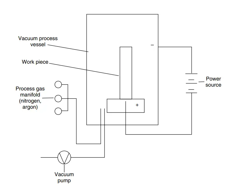
Also popular as ion nitriding or glow-discharge nitriding, plasma nitriding uses a plasma discharge of reaction gases to heat the metal surface and supply nitrogen for the nitriding process. The main advantage of plasma nitriding is that the process is not dependent on the decomposition of ammonia gas to release nascent nitrogen. Invented by Dr. Bernhardt Berghaus of Germany, Plasma nitriding has a shorter cycle time. Fig. 2 below shows a typical schematic diagram of the plasma nitriding furnace layout.
Fig. 2: Schematic of Plasma Nitriding Furnace layout
In plasma nitriding, intense high-voltage electric fields in a vacuum are used to generate ionized nitrogen gas molecules. This highly active gas with ionized molecules, known as plasma accelerates to impinge on the work surface. This ion bombardment cleans the surface, heats the workpiece, and provides active nitrogen ions. Plasma nitriding helps in close control of the nitriding microstructure and its efficiency is not dependent on the temperature.
Metallurgically versatile, the ion nitriding process provides excellent retention of surface finish and ensures repetitive metallurgical properties. Ion nitriding can be conducted at temperatures lower than those conventionally employed. The plasma nitriding process does not cause any pollution and insignificant gas consumption which are important economic and public policy factors.
What are the Advantages and Disadvantages of the Ion Nitriding Process?
The main advantages of plasma nitriding are:
Close control of Nitrided microstructure.
The working lifespan of the component also increases.
No polishing or machining is required post-nitriding process.
Causes very little or no distortion.
Energy-efficient and the fastest process.
The disadvantages of the plasma nitriding process are:
Limited only on the compound zone thickness.
Poor temperature control.
What is Salt Bath Nitriding?
Salt bath nitriding used molten salt as the source of nitrogen. The nitriding process uses the nitrogen liberated from the decomposition of cyanide to cyanate. The process also releases carbon and thus the process is also known as a nitrocarburizing treatment. The metal is normally submerged in a bath of preheated molten cyanide salt. The high concentration of nitrogen in the liquid chemically combines with iron to produce a hard and ductile iron nitride (Fe3N) thin outer layer.
What are the Advantages and Disadvantages of Salt-bath Nitriding?
The advantages of salt nitriding are:
Quick processing time and higher diffusion in the same period.
A simple operation involving the heating of the salt and workpieces to a temperature of 550 to 5700C and submerging for the specified duration.
The disadvantages of the salt bath nitriding process are:
Used cyanide salts are highly toxic.
Only one process is possible with a particular salt type.
What are the Prerequisites for Nitriding?
To get the best results in nitriding the following prerequisites should be followed:
The steel should be hardened, quenched, and tempered to get a uniform structure.
The surface must be cleaned to remove oils, grits, etc using vapor degreasing or abrasive cleaning.
Advantages of the Nitriding Process
The nitriding process provides various advantages like:
An agitator is a mechanical device that helps in shaking or stirring a liquid or mixture of liquids. Agitators are widely used for multiple operations in the chemical, pharmaceutical, food, grease, metal extraction, paint, adhesive, water, and cosmetic industries.
What are agitators used for?
The main functions of using an agitator in any plant are:
To get proper mixing of liquids.
To promote chemical reactions inside the equipment.
To increase heat transfer during heating or cooling
To keep homogeneous liquid bulk during storage.
To disperse immiscible liquids.
To keep the product in a mixed state till used.
To blend miscible liquids.
To dissolve some solids into liquid.
The agitators are defined as a machine where an impeller with a rotating shaft imparts energy by mechanical means to mix various process media.
What are the Types of Agitators?
Various types of agitators are available for industrial purposes. The common type of agitators are:
Paddle Agitators
Anchor type agitators
Propeller type agitators
Blade type agitators
Turbine type agitators
Helical Agitators
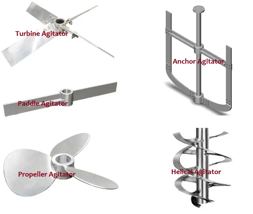
1. Paddle Agitators: Containing paddle-shaped blades, these agitators are the most basic types of agitators. Their capability is limited and used mainly for laminar flow fluids requiring little shearing. They are adjustable and contain an equal number of forwarding and reversing paddles to move ingredients from one end of the vessel to the other.
A modified version of paddle agitators is Sawtooth Paddle Agitators. The forward puddles of such agitators contain notches or saw teeth.
2. Anchor Agitators: For mixing highly viscous and non-Newtonian fluids, anchor agitators are widely used. Their name indicates the impeller shape that resembles an anchor. They are normally mounted in tanks and vessels with conical or rounded bottoms.
3. Propeller Agitators: For low-viscosity products, Propeller agitators are highly suitable. Functions like homogenization, suspension, and dispersion are easily achieved using propeller-type agitators operating at medium to high speeds. These axial flow agitators are ideal for solid-in-liquid suspensions as they prevent the deposition of solid particles.
Fig. 1: Agitator Types
4. Blade Type Agitators: These are suitable for low and medium-viscosity fluids. Blade-type agitators are axial type.
5. Turbine Agitators: For emulsification and dispersion of fluids at very high speed, Turbine agitators are used widely. Turbine Agitators are characterized by highly effective mixing capability across a broad viscosity range. Turbine agitators have an axial input and radial output. They combine rotation and centrifugal motion during work.
6. Helical Agitators: As the blades are arranged in a structure of a helix, they are known as helical agitators. Appearing like a threaded screw, helical agitators are axial flow agitators that provide vigorous motion within the vessel or tank. This type of agitator is widely used in polymer industries.
The following table provides the main applications, advantages, and disadvantages of various types of agitators.
Type of Agitator
Applications
Advantages
Disadvantages
Paddle Agitator
Mixing of Solids, Slurry Mixing, Used during the Crystals forming phase during Supersaturated Cooling
Heavy-duty, Slow Operation, 2 to 4 blades.
High power consumption, Inefficient mixing.
Turbine Agitator
Liquids and gas reactions are widely used for reaction and extraction operations.
High radial flow, good for dispersion operation.
Not preferred for highly viscous solvents
Anchor Agitators
Widely used in the pharma industry.
High heat transfer rate.
High power and high-efficiency gearbox requirement.
Propeller Agitators
Can handle corrosive materials with a glass lining.
Increase homogeneity. Can be used for drying and pressing.
High-speed requirement.
Helical Blade
The Paint Industry.
Can efficiently handle visco-elastic liquids.
Low possibility for radial Mixing.
Table 1: Comparison of different types of agitators
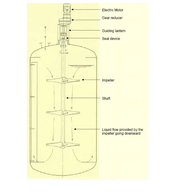
Components of an Agitator
An agitator is usually composed of three main components. they are:
A shaft with an impeller and impeller blades
A mechanical seal and
A motor with a gearbox option for speed control.
The shaft of the agitator is connected to the motor and gearbox and the impeller rotates to perform mixing. The number of impellers depends on the height of the liquid inside the vessel or tank. Each impeller usually has 2 to 6 blades. Magnetic-driven agitators are also available where a hermetic seal is used in place of a mechanical seal. Fig. 2 below shows typical components of an agitator (Reference: Wikipedia)
Fig. 2: Components of an Agitator
The impellers used in agitators can be of various types like:
Standard or Wide blade Hydrofoils
Straight blade or Pitched blade turbines.
Retreat curved impellers.
Gas dispersion impellers.
Rushton turbine impellers
Sawtooth disk impellers, etc
Selection Criteria of Industrial Agitators
The selection of agitators for a particular application depends on various factors like:
The phase to be mixed (single-phase or multiphase).
The viscosity of the bulk.
Exact function required (blending, dissolving, dispersion, heat exchange, chemical reaction, crystallization, emulsification, suspension, etc).
The mixing cycle (batch size, the time required for agitation, material addition sequence, etc)
Properties of the materials to be mixed.
Initial ingredient and final product viscosities.
Solubility of solids and concentration used.
Desired process outcomes.
Corrosive or flammable properties.
Number of Agitators
There could be more than one agitator connected to the shaft. The number of agitators and the Gap between the two agitators can be found in the following equation:
Number of Agitators=(Maximum liquid height X Specific gravity)/Diameter of the Vessel. The gap between two Agitators=Liquid Height/(Number of Impellers-0.5).
Data required for the design of an Agitator
The following data are required for the industrial design of an agitator:
Purpose/Function of agitation.
Mixing cycle.
Foaming tendency
Individual physical characters and their quantities of the materials to be mixed.
Tank/Vessel/Reactor dimensions preferably with a sketch.
Duty hours.
Electrical duties
Material of Construction
Applications of Industrial Agitators
Industrial agitators are used in various applications like