The hardness of a material can be defined as the resistance of that material to indentation and scratching. It is characteristic of materials and a very important material property. Different applications required hard materials and the hardness of that material quantifies that property. The more the value of hardness, the more hard the material is, and the more difficult will be to create an indentation under a given load. There are various industry-approved methods for hardness testing like Brinell Hardness, Rockwell Hardness, Vickers Hardness, etc. However, Rockwell hardness testing is one of the widely used, efficient, and industry-recognized methods of hardness testing that is represented using Rockwell Hardness Scales.
For material selection, process and quality control, and acceptance testing of commercial products, the Rockwell hardness test is useful. In this article, we will learn the procedure of the Rockwell hardness test, related formulas, standards, the Rockwell hardness scale, and its advantages.
What is the Rockwell Hardness Test?
Rockwell hardness test using the Rockwell hardness scale is one of the extensively used and accurate hardness test methods prevalent in industries. This testing is easier to perform as compared to Brinell or Vickers hardness test. As per the name of the inventors, Mr. Hugh M. Rockwell and Mr. Stanley P. Rockwell, this hardness test is well-known as Rockwell hardness testing.
Rockwell hardness test is widely used for thin steel, lead, brass, zinc, aluminum, cemented carbides, iron, titanium, copper alloys, and certain plastics. This test is considered one of the simple and quick hardness testing methods.
Rockwell hardness testing is performed by comparing the penetration depth measurement of an indenter under a large load known as a major load and a smaller preload known as a minor load.
Types of Rockwell Hardness Tests
Depending on the applications of minor and major loads during the test, the Rockwell hardness test is categorized into two groups. They are:
- Regular Rockwell Hardness Test where the minor load is 10 kgf and major load is 60, 100, or 150 kgf.
- Superficial Rockwell Hardness Test where the applied minor load is 3 kgf and the major loads are 15, 30, or 45 kgf.
Rockwell Hardness Test Procedure
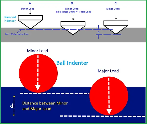
The procedure for the Rockwell Hardness test consists of the application of a minor load followed by a major load. The minor load is applied to establish the zero position from where the measurement will be taken. Next, the major load is applied and then removed while still maintaining the minor load. The penetration depth (d) from the zero datum position is measured by a dial.
A pre-decided minor and major load are applied on the test specimen by a diamond or ball indenter. The minor load (3 kgf to 10 kgf) reduces the effect of the surface finish. After that, the additional load or major load (15 kgf to 150 kgf) is applied for a specified dwell time. Now the major load is released and the final depth of indentation from the preload position to the combined load position is measured which is converted to the Rockwell hardness number. Then the preload is released and the indenter is removed from the sample. Refer to Fig. 1 below that explains the Rockwell hardness test procedure.
The procedure of the Rockwell hardness test consists of the following steps:
- Setting the test specimen sample on a flat, solid surface.
- Applying the minor load to create a slight impression (zero point position).
- Setting the measuring gauge and measuring the initial indentation depth under minor load.
- Applying the major load and holding for the dwell time.
- Removing the major load, keeping the minor load.
- Measuring the depth of penetration from zero position.
- Finding the Rockwell hardness number from the penetration depth.
Rockwell Hardness Test Formula
Rockwell hardness test is directly read from the equipment. However, there is a formula to convert the measured depth (d) into the Rockwell hardness number. A Rockwell hardness number for a material is a unitless number indicating the hardness value on a specified Rockwell scale.
The equation for Rockwell Hardness Number is given by
HR=N-(d/s)
Where,
- N and s are scale factors depending on the test being used. The value of N is either 100 or 130 depending on the Rockwell hardness scale used. Similarly, the value of s is either 0.001 mm or 0.002 mm.
- d is the penetration depth measured from zero points (in mm).
Rockwell Hardness Scale
Rockwell hardness scale is a type of scale that indicates the hardness of a material measured using the Rockwell hardness test. It is a unitless number. The Rockwell hardness scale is symbolized by HR followed by a letter indicating any of the possible scales. For example, “HRC 96” for a metal means the hardness of that metal is 96 when measured using Rockwell hardness scale C.
Manufactured products are made of different types of materials. To accommodate the hardness testing of this diverse range, several different indenter types are used in the Rockwell hardness testing along with a range of standard force levels. Each combination of indenter type and applied force levels has been defined using a distinct Rockwell hardness scale. As per ASTM E 18, there are thirty (30) different Rockwell scales divided into two categories: regular Rockwell scales and superficial Rockwell scales.
There are several different Rockwell Scales denoted by various letters requiring different loads or indenters during hardness testing. The Rockwell hardness scale chart for regular Rockwell scales and superficial Rockwell scales are provided in table 1 and 2 below:
| Rockwell Scale Symbol | Type of Indenter/Diameter in case of Ball | Minor Load | Major Load | Typical use |
| HRA | Spheroconical diamond | 98.07 N (10 kgf) | 588.4 N (60 kgf) | Cemented carbides, thin steel, and shallow case hardened steel. |
| HRB | Ball, 1.588 mm (¹⁄₁₆ inches) | 98.07 N (10 kgf) | 980.7 N (100 kgf) | Copper alloys, soft steels, aluminum alloys, malleable iron, etc. |
| HRC | Spheroconical diamond | 98.07 N (10 kgf) | 1471 N (150 kgf) | Steel, hard cast irons, pearlitic malleable iron, titanium, deep case hardened steel, and other materials harder than 100 on the Rockwell B scale. |
| HRD | Spheroconical diamond | 98.07 N (10 kgf) | 980.7 N (100 kgf) | Thin steel and medium case hardened steel, and pearlitic malleable iron. |
| HRE | Ball, 3.175 mm (⅛ inches) | 98.07 N (10 kgf) | 980.7 N (100 kgf) | Cast iron, aluminum and magnesium alloys, and bearing metals. |
| HRF | Ball, 1.588 mm (¹⁄₁₆ inches) | 98.07 N (10 kgf) | 588.4 N (60 kgf) | Annealed copper alloys, and thin soft sheet metals. |
| HRG | Ball, 1.588 mm (¹⁄₁₆ inches) | 98.07 N (10 kgf) | 1471 N (150 kgf) | Malleable irons, copper-nickel-zinc and cupronickel alloys. |
| HRH | Ball, 3.175 mm (⅛ inches) | 98.07 N (10 kgf) | 588.4 N (60 kgf) | Aluminum, zinc, and lead. |
| HRK | Ball, 3.175 mm (⅛″) | 98.07 N (10 kgf) | 1471 N (150 kgf) | Bearing metals and other very soft or thin materials. |
| HRL | Ball, 6.350 mm (¼ inches) | 98.07 N (10 kgf) | 588.4 N (60 kgf) | Bearing metals and other very soft or thin materials. |
| HRM | Ball, 6.350 mm (¼ inches) | 98.07 N (10 kgf) | 980.7 N (100 kgf) | Bearing metals and other very soft or thin materials. |
| HRP | Ball, 6.350 mm (¼ inches) | 98.07 N (10 kgf) | 1471 N (150 kgf) | Bearing metals and other very soft or thin materials. |
| HRR | Ball, 12.70 mm (½ inches) | 98.07 N (10 kgf) | 588.4 N (60 kgf) | Bearing metals and other very soft or thin materials. |
| HRS | Ball, 12.70 mm (½ inches) | 98.07 N (10 kgf) | 980.7 N (100 kgf) | Bearing metals and other very soft or thin materials. |
| HRV | Ball, 12.70 mm (½ inches) | 98.07 N (10 kgf) | 1471 N (150 kgf) | Bearing metals and other very soft or thin materials. |
| Rockwell Scale Symbol | Type of Indenter/Diameter in case of Ball | Minor Load, N (kgf) | Major Load, N (kgf) | Typical use |
| 15N | Spheroconical diamond | 29.42(3) | 147.1 (15) | Similar to A, C, D scales in table-1 but for thinner gage material. |
| 30N | Spheroconical diamond | 29.42(3) | 294.2 (30) | Similar to A, C, D scales in table-1 but for thinner gage material. |
| 45N | Spheroconical diamond | 29.42(3) | 441.3 (45) | Similar to A, C, D scales in table-1 but for thinner gage material. |
| 15T | Ball; 1.588 mm (1/16 inches) | 29.42(3) | 147.1 (15) | Similar to B, F, G scales in table-1 but for thinner gage material. |
| 30T | Ball; 1.588 mm (1/16 inches) | 29.42(3) | 294.2 (30) | Similar to B, F, G scales in table-1 but for thinner gage material. |
| 45T | Ball; 1.588 mm (1/16 inches) | 29.42(3) | 441.3 (45) | Similar to B, F, G scales in table-1 but for thinner gage material. |
| 15W | Ball; 3.175 mm (1/8 inches) | 29.42(3) | 147.1 (15) | Very Soft Material |
| 30W | Ball; 3.175 mm (1/8 inches) | 29.42(3) | 294.2 (30) | Very Soft Material |
| 45W | Ball; 3.175 mm (1/8 inches) | 29.42(3) | 441.3 (45) | Very Soft Material |
| 15X | Ball; 6.35 mm (1/4 inches) | 29.42(3) | 147.1 (15) | Very Soft Material |
| 30X | Ball; 6.35 mm (1/4 inches) | 29.42(3) | 294.2 (30) | Very Soft Material |
| 45X | Ball; 6.35 mm (1/4 inches) | 29.42(3) | 441.3 (45) | Very Soft Material |
| 15Y | Ball; 12.70 mm (1/2 inches) | 29.42(3) | 147.1 (15) | Very Soft Material |
| 30Y | Ball; 12.70 mm (1/2 inches) | 29.42(3) | 294.2 (30) | Very Soft Material |
| 45Y | Ball; 12.70 mm (1/2 inches) | 29.42(3) | 441.3 (45) | Very Soft Material |
Factors for Selecting Appropriate Rockwell Scale
Choosing the right Rockwell scale is difficult as various parameters affect the selection process. The major factors to be considered for Rockwell scale selection are:
- the type of hardness test material
- the thickness of the test material
- the area or width of the test material
- the limitations of each Rockwell hardness scale
- the test material homogeneity.
Standards for Rockwell Hardness Testing
The widely used standards that govern the Rockwell hardness testing methodology are:
- ASTM E18 for Metals
- ISO 6508 for Metals,
- ASTM D785 for Plastics
- ISO 2039 for Plastics
Rockwell Hardness Test Machine
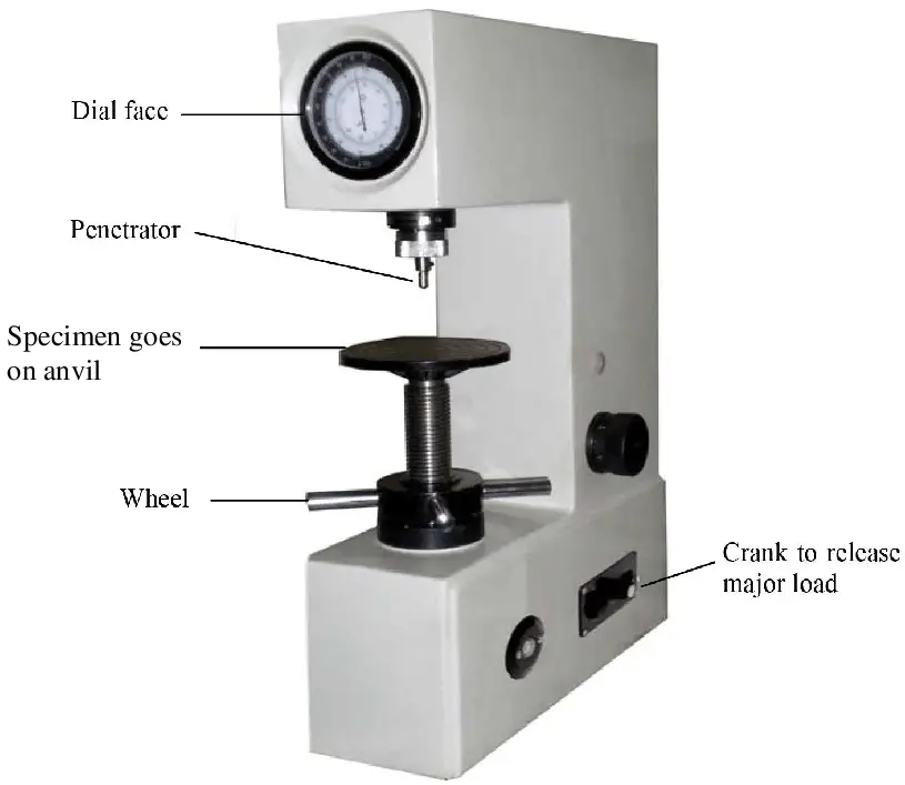
A wide range of Rockwell hardness tester machines is available to find out the hardness values of materials. It can vary from manual and semi-automatic to fully automatic advanced ones. Refer to Fig. 2 below that provides the major components of a typical Rockwell hardness testing machine.
Factors Affecting the Accuracy and Reliability of Rockwell Hardness Testing
There are various parameters that affect the accuracy, precision, and reliability of the Rockwell hardness testing method. Those are:
- Rockwell test machine: Test results can vary due to variability from the equipment, operator, and environmental conditions. So, it must be ensured that the machine condition, and specimen set-up by the operator are correct.
- Presence of dirt or grease in the contact area.
- Specimen Surface: Surface conditions must be of good quality to get more accurate and reproducible test results.
- Operator Skill: the operator must be highly skilled in proper fixing and testing techniques. Otherwise, test results can vary significantly.
Typical Rockwell Hardness Values
The following table (Table 3) provides some typical values of Rockwell hardness
| Material | Rockwell Hardness Values |
| Very Hard Steel | HRC 55 to HRC 66 |
| Axes | HRC 45 to HRC 55 |
| Brass | HRB 55 to HRB 93 |
| Hard Impact Steel Blades | HRC 52 to HRC 55 |
Advantages of Rockwell Hardness Testing
Rockwell hardness testing provides significant advantages with respect to other hard test methods as listed below:
- Rockwell hardness test displays hardness values directly. So no calculation is required to find the hardness value.
- It is a fast, reliable, and robust method with a small area of indentation.
Rockwell Hardness Test vs Brinell hardness Test
The details of the Brinell hardness test and the main differences between the Rockwell and Brinell hardness test are published in a separate article. Kindly click here to visit that article.