Recent Posts

Welding Positions: Pipe Welding Positions

A welding position is a technique by which a welder joins the metals in positions or angles. The welding position is very important as it affects the flow of molten filler material. It’s desirable that the welding operator understands the types of welding positions to smoothly accomplish the task. Also, at a certain position of the welder different welding processes are performed. In this article, we will learn about the common welding positions used in the industrial application of welding.

The guidelines and limitations regarding welding positions in WPS are covered in Section IX of the ASME Boiler and Pressure Vessel Code.

Types of Welding Positions

Some welding processes can be performed at all positions; while some are possible in one or two positions only. According to the positions of the welding joint on sections, the American Welding Society (AWS) and ASME define four types of welding positions. They are

  • Flat welding position
  • Horizontal welding position
  • Vertical welding position, and
  • Overhead welding position

The welding position is defined by a number (1 to 6) followed by one letter from F, G, or S. Here, the letter “F” stands for fillet welding, “G” denotes Groove welding, and “S” refers to Stud welding.
The numbers denote welding positions as follows:

  • “1” indicates a flat position. For example, 1F, 1G or 1S
  • “2” refers to a horizontal welding position; Example 2F, 2G or 2S
  • “3” denotes a vertical position; for Example 3F or 3G
  • “4” denotes an overhead position; for Example, 4F, 4G, or 4S.
  • Letters “5” and “6” are specifically used for piping welding positions in a horizontal fixed position and inclined position respectively. Pipe welding positions will be discussed toward the end of the article.

The following table shows the various welding symbols for welding positions used for different types of welding methods

Welding Position SymbolWelding PositionWeld Type
1 FFlat positionFillet weld
1 GFlat positionGroove weld
1SFlat positionStud Weld
2 FHorizontal positionFillet weld
2 GHorizontal positionGroove weld
2SHorizontal positionStud Weld
3 FVertical positionFillet weld
3 GVertical positionGroove weld
4 FOverhead positionFillet weld
4 GOverhead positionGroove weld
4SOverhead positionStud Weld
Table 1: Welding position symbols with respect to Welding types

Welding Positions 1G or 1F (Flat welding positions)

In Flat Welding position 1G or 1F, the welding is done from the top side of the joint. The head of the welder remains above the test coupon and the weld face is approximately horizontal. The flat welding position is easier and faster and the molten metal is drawn downward. A flat welding position is also known as a down-hand welding position.

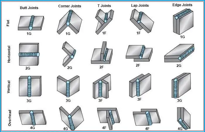
The following image in Fig. 1 shows the welding positions used during welding.
Weld Joint Positions
Fig. 1: Weld Joint Positions for plate

Welding Positions 2G or 2F (Horizontal welding positions)

In the horizontal welding position, the weld axis is almost horizontal. Compared to a flat welding position, this is a more difficult position for welding.

Welding position 2F is for a fillet weld where the welding is performed on the upper side of a horizontal surface and against an approximately vertical surface keeping to welding torch at a 45-degree angle.

Welding position 2G is for a groove weld when the welding face lies in an approximately vertical plane with the weld axis in a horizontal plane.

Welding Position 3G or 3F (Vertical welding positions)

In vertical position welding, the weld axis is almost vertical. Both the weld and the plate will lie vertically. For welding vertical surfaces, the molten metal runs downward by gravity and piles up. Welding in an upward or downhill vertical position can resolve this problem. Also, by pointing the flame upward at around a 45-degree angle to the plate, the metal flow can be controlled. Welding position 3G is used for groove welding and 3F is used for fillet welding.

Welding Position 4G or 4F (Overhead weld position)

When the welding is done from the underside of the joint, it is known as the overhead welding position. It’s the most difficult position for a welder to work and the most complicated one. Welding Position 4G refers to groove welding and 4F indicates fillet welding.

In overhead welding positions, the metal deposited tends to drop or sag on the plate which results in a bead with a high crown. To get rid of this difficulty, the molten puddle should be kept small. When the puddle becomes too large, one can remove the flame momentarily for the molten metal to cool.

Pipe Welding Positions

The above-mentioned welding positions, i.e, flat, horizontal, vertical, and overhead are the most basic types of welding positions used for plate welding. However, these do not completely describe pipe welding positions. As far as pipe welding is concerned, there are four types of piping welding positions. They are:

  • Horizontal Rolled Pipe Weld Position 1G
  • Vertical Position 2G
  • Horizontal Fixed Position 5G, and
  • Inclined Weld Position 6G

Pipe Welding Positions 1G

Welding Position 1G is the easiest pipe welding position as the pipe is in a horizontal position. In a 1G pipe welding position, the pipe can be rotated against its horizontal axis (X-axis). The welder performs pipe welding from the top without changing his position while the pipe is slowly rotated manually or by equipment. Pipe Weld Position 1G is the most basic pipe welding.

The image in Fig. 2 below explains all the pipe welding positions.
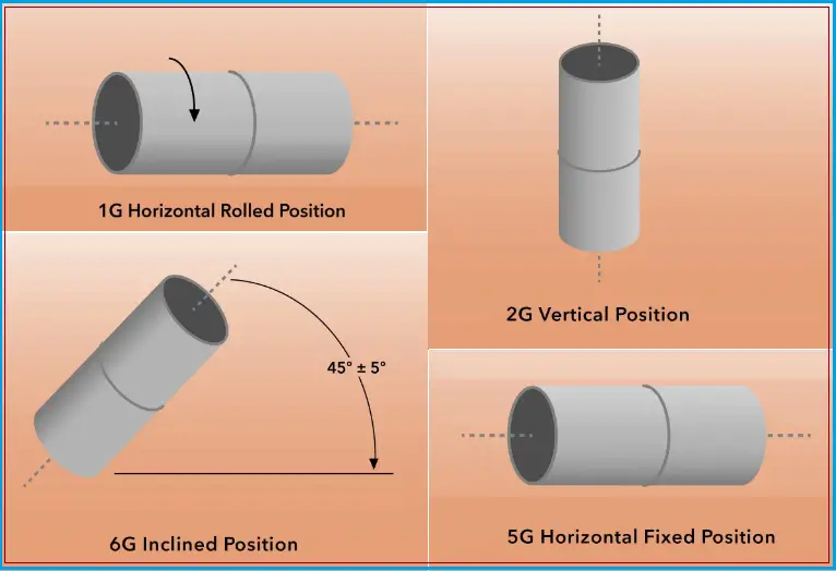
Fig. 2: Pipe Welding Positions

Pipe Welding Positions 2G

In pipe welding position 2G, the pipe will be in the vertical position (Pipe axis in the Y direction) and the weld axis in the horizontal direction. The welder performs the welding from the side by remaining stationary or moving around the pipe. The welding method is easy in the case of a 2G pipe welding position and is most frequently welded by the backhand method.

Welding Positions 5G

Pipe welding position 5G is a weld position where the pipe axis is fixed in a horizontal position and the operator weld vertically either downward or upward. In this welding position, the pipe is kept fixed and can not be rotated, unlike 1G welding. 5G welding position is difficult as the pipe can not be rotated.

Welding Positions 6G

In pipe welding position 6G, welding is performed in a sloping pipe. The pipe slope is normally 45 degrees from a horizontal or vertical axis. 6G welding positions, being the most difficult pipe welding positions, require certified and highly experienced welders. The pipe remains fixed and the operator needs to move around the pipe for welding. This is the most challenging and complex pipe welding position for welders.

There is another form known as 6GR where welding is done in a ring mode by placing a steel plate below the weld with a 1-inch gap. This requirement comes while welding pipes near impediments like walls, brackets, or other structures.

Comparisons of welding positions between ISO standard and ASME / AWS standard

Sometimes, the weld positions by professional organization ISO are found in industries. The weld position nomenclature in the ISO system is a bit different. The following table provides a comparison between ISO and AWS standard welding position symbols.

AWS Welding PositionISO Welding Position
1G / 1FPA
2FPB
2GPC
4FPD
4GPE
3G UphillPF
3G DownhillPG
5G UphillPH
5G DownhillPJ
6G UphillH-L045
6G DownhillJ-L045
Table 2: AWS vs ISO welding positions

Why care about Pipe Welding Positions?

Welding position is one of the most important variables that determine weld quality. For each pipe weld position, welders need to undergo certification processes. If a welder is qualified to weld in a 1G position, he is not allowed to weld hard positions like the 6G position. But on the other hand, if the welder is certified for the hardest 6G position then he can work in the 1G position. So, expertise in each weld position levels up a welder’s skills and qualifications.

Frequently Asked Questions related to Welding Positions

  1. What are the 5 welding positions?
    As described above, the 5 major welding positions widely used in the welding industry are flat weld, horizontal weld, overhead weld, vertical weld, and piping weld. These welding positions are designated by a number and followed by a letter.
  2. What are 5G and 6G welding?
    Weld positions 5G and 6G are pipe welding positions. The 5G is welding in a horizontal fixed position whereas the 6G is welding in an inclined fixed position that is about 45 degrees. Refer to Fig. 2 above for a proper understanding of the 5G and 6G welding positions.
  3. How much does a 6G welder make in the United States?
    The salary of welders depends on various factors like the experience of the welder, demand and supply, etc. However, in general, the salary of a 6G welder in the United States varies between $30, 000 to $67,000 per year.
  4. Which position is advantageous for easy welding?
    The horizontal welding position is the easiest, safest, and most ergonomic for a welder.
  5. How hard is 6G welding?
    The 6G pipe welding is one of the most difficult weldings as the pipe is at a 45-degree angle and immovable. So, only experienced and certified 6G welders can perform these jobs efficiently at the construction site.

Few more welding articles for you.

Welding Galvanized Steel
Overview of Pipeline Welding
Welding Positions: Pipe Welding Positions
Welding Defects: Defects in Welding: Types of Welding Defects
Welding Inspector: CSWIP and AWS-CWI
General requirements for Field Welding
Underwater Welding & Inspection Overview
Methods for Welding Stainless Steel

Video Courses in Welding

To learn more about welding the following video courses you can refer to:

Fire Extinguisher: Meaning, Classes, Types, Selection, Use, Inspection

In your office or any workplace, you must have seen fire extinguishers placed in distinct identifiable locations. It is a mandatory safety requirement to keep fire extinguishers in places where there are possibilities of fire hazards. But most of us do not know many details about this widely used fire protection device. In this article, we will explore more details about fire extinguishers, their types, selection, and inspection requirements.

Fire Extinguisher Meaning

A fire extinguisher is an active fire protection device for controlling or extinguishing small accidental fires. During emergency situations, a fire extinguisher can control a small fire. However, these devices should not be used for out-of-control fire events that endanger the user. Usually, a fire extinguisher consists of a cylindrical pressure vessel containing an agent that has the capability to extinguish a fire when discharged. A person can easily operate this device. Non-cylindrical Fire extinguishers are also available but are less common.

Fire Extinguisher Parts

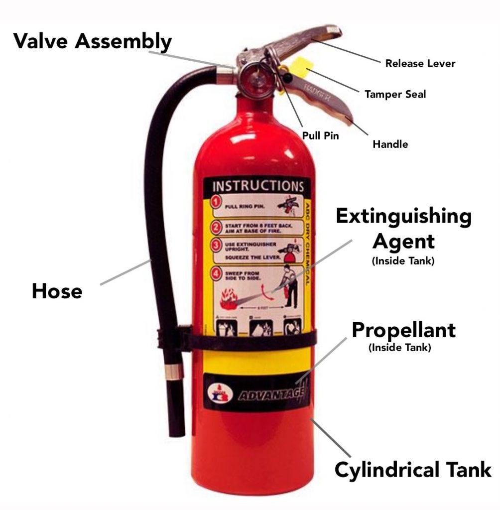
Usually, most fire extinguishers consist of similar parts and components even though the extinguishing agent may differ. Common fire extinguisher parts are:

  • a cylindrical tank containing propellant and an extinguishing agent.
  • a release system comprised of a squeeze handle, a valve assembly, and a release lever.
  • a safety mechanism comprised of a tamper seal and a pull pin.
  • a hose for directing the extinguishing agent.

The following figure (Fig. 1) shows the typical fire extinguisher parts:

Fire Extinguisher Parts
Fig. 1: Fire Extinguisher Parts

Classes of Fire Extinguisher

Depending on the specific fire types, fire extinguishers are also classified into six groups as listed below:

Class A fire extinguisher: These fire extinguishers are used to put out class A fires characterized by fire from ordinary solid or dust combustibles like wood, paper, textile, plastic, fabric, cardboard, etc.
Class B fire extinguishers: Class B fire extinguishers are used to prevent Class B fire hazards from flammable liquids like grease, gasoline, oil (except cooking oil), paint, etc.
Class C fire extinguisher: Class C fires originating from flammable gases like methane, butane, propane, hydrogen, etc are best handled using class C fire extinguishers.
Class D fire extinguisher: Class D fire extinguishers are widely used to put out fires generated from combustible metals, such as magnesium, sodium, potassium, lithium, titanium, or aluminum.
Class E fire extinguisher: These fire extinguishers are used to extinguish fires that originated from live electrical sources. However, in many countries, this is not recognized as a separate fire class because once the electric power supply is switched off it can be considered as any of the other five classes.
Class F fire extinguisher: Class F fire extinguishers find their use to extinguish class F fires characterized by fires from cooking oils, vegetable oils, fats, butter, etc.

Note that, the above fire extinguisher classes slightly vary from country to country. The comparison is tabulated below for guidance:

AmericanEuropeanUKAustralian/AsianFuel/heat source
Class AClass AClass AClass AOrdinary combustibles
Class BClass BClass BClass BFlammable liquids
Class BClass CClass CClass CFlammable gases
Class CUnclassifiedUnclassifiedClass EElectrical equipment
Class DClass DClass DClass DCombustible metals
Class KClass FClass FClass FCooking oil or fat
Table 1: Comparison of fire extinguisher classes

Types of Fire Extinguishers

Based on the content inside the vessel, 6 main types of fire extinguishers are available. They are:

  • Water fire extinguishers
  • Foam fire extinguishers
  • Powder fire extinguishers
  • Carbon dioxide (CO2) fire extinguishers
  • Wet chemical fire extinguishers
  • Clean agent fire extinguishers.

Water Fire Extinguishers:

Water fire extinguishers are the most economic and simplest among all fire extinguisher types. They are suitable to put off class A fires. All water extinguishers have a bright red label. Water fire extinguishers are widely used in shops, domestic buildings, offices, retail premises, schools, hotels, warehouses, hospitals, etc. Water fire extinguishers are of four types:

  • Water jet extinguishers
  • Water spray extinguishers
  • Water extinguishers with additives, and
  • Water mist extinguishers

A water jet extinguisher throws a water jet at the burning material forcing the material to cool down and preventing re-ignition. Water spray fire extinguishers use a very fine spray of water droplets surrounded by air to extinguish the fire.

A foaming chemical is added to the water fire extinguishers with additives that help in effective soaking into the burning materials. The addition of chemicals can cause a smaller fire extinguisher to produce the same fire-fighting capability as a larger, water-only, fire extinguisher.

Water mist fire extinguishers apply water in the form of fog or mist. The generated mist droplets are much smaller as compared to those formed in the water spray fire extinguisher. Smaller droplets possess larger surface areas in relation to their size. Such smaller droplets evaporate quickly absorbing the heat energy from the fire.

Foam Fire Extinguishers:

Foam fire extinguishers find their application to put out class A and class B fires. They blanket the fire with a foam generated when the spray hits the air. This blanket prevents the vapors from reaching the air. Also, the water in the foam provides a cooling effect to prevent re-ignition. Foam fire extinguishers carry a cream label.

Powder Fire Extinguishers:

Powder fire extinguishers are multi-purpose extinguishers with numerous advantages. It is one of the most common extinguishers in wide use as powder extinguishers can be effectively used on Class A, B, C, and E fires. Fine chemicals in powder form as extinguishing agents are released by the powder extinguishers to blanket the fire and suffocate it. The common powder is mono-ammonium phosphate.

However, as they do not cool the fire, there is a possibility of re-ignition. Also, powders can create a loss of visibility and breathing problems. So, powder extinguishers should be used as the last resort. Powder fire extinguishers carry a blue label.

Carbon Di-Oxide Fire Extinguishers:

A carbon dioxide fire extinguisher (CO2) is ideal for fires involving electrical hazards (Class E). This is one of the cleanest types of fire extinguishers in commercial use and requires no clean-up after use. CO2 fire extinguishers can also be used on class B fires involving flammable liquids.

Carbon dioxide fire extinguishers blanket the fire by cutting off the air supply which in turn removes oxygen, required for the fire to continue. CO2 fire extinguishers carry a black label.

Wet Chemical Fire Extinguishers:

Wet chemical extinguishers are highly efficient extinguishers and ideal for fire hazards involving cooking oils and vegetable fats (Type F or type K fire class). They contain a potassium solution that rapidly knocks the flames out, cools the hot oil, and seals the liquid surface with a thick soap-like substance generated by a chemical reaction. This soap-like substance prevents re-ignition. Wet chemical fire extinguishers can also be used for class A fires and they carry a yellow label.

Clean Agent Fire Extinguishers:

A clean agent fire extinguisher is a gaseous fire suppression system. The agent in its liquid phase is stored in the cylinder. When it is sprayed through the nozzle, the clean agent converts into a non-conductive, safe eco-friendly gas upon contact with the air. The gas extinguishes the fire by reducing the oxygen levels and impeding the chain reaction. They are ideal and widely used for class B and E-type fires.

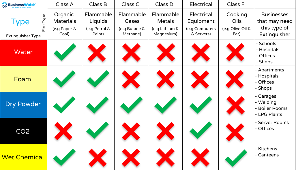
The following image in Fig. 2 provides a quick reference fire extinguisher type chart:

Fire Extinguisher Types Chart
Fig. 2: Quick Reference Fire Extinguisher Types Chart

Automatic fire extinguishers

Automatic fire extinguishers are used to fight transport fires (engine compartments of boats or large vehicles, or in industrial use, such as in generator or computer rooms). They are automatic, and easy to recharge. Once they detect heat, Automatic fire extinguishers immediately act. They are suitable for Class A, B, C, and electrical fires and contain dry powder or clean inert gases as the extinguishing agent.

Selection of Fire Extinguisher

To select a fire extinguisher, one needs to identify the fire class. Knowing the reason or origin of the fire hazard can be helpful in determining the fire class. The chart in Fig. 2 will be helpful in deciding a specific fire extinguisher type selection. If the fire hazard contains a mix of fire classes, it is important to select an extinguisher that can control all of the hazards present. The manufacturers provide the rating for the extinguisher and that is specified on the product label affixed to the extinguisher. The main factors that should be considered while selecting a fire extinguisher are:

  • Fire Extinguishers of certain fire hazard types may not be effective against fires of a different hazard class. Even, it may increase the fire severity if not selected carefully.
  • Extinguishers intended for certain types of hazards can increase personnel hazards for users when used against different hazard-class fires.
  • Extinguishers rated for multiple fire hazards may have different levels of effectiveness for each hazard.
  • Fires involving metals are controlled by class D extinguishers. Note that, an extinguisher that may be highly effective in one type of metal fire, may be dangerous in other types of metallic fires.
  • Class F (K) fire extinguishers for controlling kitchen fire exposures may not be suitable for conventional usage.

How to Use a Fire Extinguisher

It is the responsibility of the employer to educate designated employees on how to use a fire extinguisher during emergency situations. It is part of a mandatory emergency fire evacuation plan. The specified person must know the locations and the types of extinguishers in the workplace.

As fire extinguishers are usually heavy, frequent practice of picking up and holding the extinguisher is advantageous. Also, the user must read the operating instructions and warnings mentioned on the fire extinguisher label.

Now to use a fire extinguisher, a simple technique known as the PASS fire extinguisher technique is used. This is a four-step method as described below:

  1. Pull: Pull the pin to break the tamper seal.
  2. Aim: Aim the nozzle or hose at the base of the fire from the recommended safe distance. For CO2 fire extinguishers, care must be exercised not to touch the horn as the severe cold can damage the skin.
  3. Squeeze: Squeeze the handle or operating lever to release the fire extinguishing agent.
  4. Sweep: Sweep the nozzle from side to side at the base of the fire until the fire appears to be out. If fire re-ignites steps from 2 to 4 should be repeated.

Using this PASS fire extinguishing methodology, small fires can easily be prevented. But remember to evacuate immediately in case of the slightest doubt regarding the capability to fight a fire.

Fire Extinguisher Inspection

NFPA 10 provides the guidelines for Fire Extinguisher Inspection Requirements to ensure the extinguisher works fine during fire events. Usually, a fire extinguisher inspection is conducted monthly by safety officers or external professionals. The inspection of fire extinguishers consists of the following steps:

  • Check Accessibility: Ensure that the fire extinguishers are available at the designated accessible places and clearly visible and unobstructed.
  • Examine the Physical State: Thoroughly examine the extinguisher for any physical damage, clogged nozzle, corrosion, leakage, etc. The locking pin should be intact and the tamper seal unbroken. The fire extinguisher operating instructions should be clearly visible.
  • Inspect the Pressure Gauge and Weight of the extinguisher: Ensure that the dial indicator of the pressure gauge is in the operable range. Also, ensure that the fire extinguisher is full by weighing or lifting the device. For wheeled fire extinguishers, confirm the condition of tires, wheels, carriage, and hose, and that the nozzle is good for working.
  • Check the inspection tag: The inspection tag should be filled to ensure that the fire extinguisher is regularly inspected.
  • Recommended action and closeout report: Any observation should be informed to the concerned person for necessary action and a report must be prepared indicating the date of inspection. Such fire extinguisher inspection reports must be maintained for at least 12 months.

Depending on the type of extinguisher, an internal examination of fire extinguishers must be conducted within 1-6 year intervals.

Online Classes for Fire Safety

If you wish to know more and enhance your knowledge of Fire safety, you can join any of the below-mentioned online classes. To start the course click on the subject of your interest, read the complete details, and then enroll in the class:

What is Liquefied Petroleum Gas or LPG?

Liquefied Petroleum Gas, commonly known as LPG, plays a vital role in our daily lives, offering a clean, efficient, and reliable source of energy for various applications. Whether it’s for cooking in households, fuel for vehicles, or even heating homes and businesses, LPG is an indispensable fuel globally. Liquefied Petroleum Gas or LPG is a non-renewable source of energy. It is the backbone of cooking, transport, heating, and industry for millions of people worldwide. It is an outstanding upgrade to air quality, efficiency, and climate friendliness as compared to other traditional fuels. It is a responsible source of energy.

The name sounds a bit contradictory as to how something can be both gas and liquid. Because the first one can fly in the air and the second one can splash in a pool. In simple terms, if you see, you will find LPG as a gas under normal pressure and temperature in your living room or garden. But it changes into liquid form when put under pressure or it is cooled down.  

What is Liquified Petroleum Gas (LPG)?

LPG is a group of hydrocarbon gases, primarily propane (C₃H₈) and butane (C₄H₁₀), that are compressed into a liquid form for ease of storage and transportation. These gases are naturally occurring in crude oil and natural gas deposits or are produced during the refining of crude oil. In its liquid form, LPG occupies much less space than in its gaseous state, making it convenient to store in pressurized containers.

Liquefied Petroleum Gas is extracted from crude oil and natural gas. It is composed of hydrocarbons containing some carbon atoms, maybe three or four. It is a flammable mixture containing hydrocarbon gases Propane (C3H8) and butane (C4H10) are the normal components of liquefied petroleum gas. Other hydrocarbons in small concentrations may also be present. It is a flammable mixture containing hydrocarbon gases that are used as fuel in heating appliances, vehicles, and cooking equipment. It contains 48 percent propane, 50 percent butane, and 2 percent pentane.

What is LPG?
Fig. 1: What is LPG?

Varieties of LPG that are bought and sold include mixes that contain mostly propane and butane and also sometimes include mixes of both propane and butane. In the areas of the northern hemisphere winter, mixes of more propane are found whereas, in summer, it contains more butane.

Two grades of LPG are sold in the United States mainly commercial propane and HD-5. Other hydrocarbons such as Propylene and butylenes are also present in small concentrations such as ethane (C2H6), methane (CH4), and propane (C3H8). A powerful odorant known as ethanethiol is added to LPG so that leaks can be detected easily. EN 589 is the internationally recognized European standard. In Australia, liquefied petroleum gas is just propane. In other words, all LPG is not propane but propane is LPG.

Liquefied petroleum gas has an energy content similar to petrol and twice the heat energy of natural gas and it burns readily in the air which makes LPG an excellent fuel for cooking, heating, and automotive use.

Where does Liquefied Petroleum Gas come from?

It all starts with nature. Liquefied petroleum gas was first found in 1910. It was then found that petroleum, diesel, gasoline, and heating oil also contain LPG and this was discovered by the American chemist Dr. Walter O. Snellling. Propane and butane are naturally occurring which make up an LPG.

The majority of liquefied petroleum gas is recovered during oil and natural gas extraction while the remaining 40% is made from waste or renewable vegetable oils or is a co-product of oil refining. As LPG is a fossil fuel, it comes from oil and gas wells. Liquefied petroleum gas is stored in liquid form in a steel container, tank, or cylinder under pressure. The pressure inside the container is dependent on the type of LPG used, be it commercial propane or commercial butane, and the outside temperature.

The Production Process of LPG

LPG is either extracted during the refining of crude oil or as a byproduct from natural gas processing. Here’s a breakdown of the production process:

  1. Natural Gas Processing: When natural gas is extracted from the earth, it contains several components, including methane, propane, butane, and other gases. The heavier hydrocarbons like propane and butane are separated from the methane (the main component of natural gas) through a process called fractionation.
  2. Crude Oil Refining: During the refining of crude oil, LPG is produced as a byproduct when refining heavier hydrocarbons into lighter products like gasoline and diesel. It’s separated out during the distillation process.

Once produced, LPG is stored in large tanks or transported in pressurized cylinders to various consumer and industrial sectors.

Characteristics of Liquefied Petroleum Gas

There are some of the features of LPG that make it unique on its own.

  1. When petroleum gas changes from a gaseous to a liquid state, it shrinks significantly. It becomes easy to transport lots of energy in a small space as the volume of the liquid is only 1/250 of the gas.
  2. When the liquid inside the cylinder is heated up or when we release the pressure by opening the valve, the liquid changes into vapor form.
  3. The liquid which is turned into vapor is heavier than air. In the case where a cylinder or tank is leaking then it will first change into vapor and then slowly start spreading close to the ground.
  4. Chemically, liquefied petroleum gas is made up of propane, butane, or a mix of the two, and also it contains hydrogen and carbon atoms.

Why choose LPG?

Characteristics of LPG
Fig. 2 Characteristics of LPG

There are several reasons why one should choose LPG and there are a thousand applications that run on LPG. The list is long and includes everything from hot air balloons to cars and heating and BBQs. In other words, it is an extremely versatile fuel. It is used all over the world by millions of people for different purposes with the same result.

The production of LPG globally has increased to 300 million tons per year. In the case where half of its demand comes from the domestic sector using the same for cooking or heating. There are several reasons why one should choose LPG and these are as follows:

Versatility

This is one of the outstanding qualities of LPG. It is one of the most flexible fuels without any comparison and due to its many applications, it is often referred to as a multipurpose form of energy.

Versatile uses of LPG
Fig. 3: Versatile uses of LPG

Efficiency

LPG is packed with energy. It is extremely efficient. As compared to other energy fuels such as petrol, diesel, coal, and natural gas, it is richer in energy. It has a higher calorific value. In other words, when you set an LPG on fire, the flame temperature will be drastically higher as compared to other fuels which means this results in higher efficiency with a rising temperature.

 As compared to other traditional fuels, LPG is five times more efficient. Hence using an LPG makes it the best way to use most of the planet’s resources. LPG’s high efficiency is one of the most unparallel advantages for both planet and people which makes it one of the best reasons to choose. LPG always keeps its power for good whereas other traditional fuels deteriorate over a period of time.

Easy Storage and Transportation

LPG can be easily stored and transported from one place to another, thereby making it more flexible and practical. The refillable cylinders or tanks are some of its storage options either above or under the ground. For cooking, cylinders are used, while cylinders are used for applications where a constant supply of energy is required.

There is a wide variety of packaging and transportation options available these days. LPG can be transported by sea, rail, or by road to people who need it. It can travel freely, unlike natural gas and electricity, which are tied up through wires or lines, which requires a complicated infrastructure setup. The reason it is easily accessible to people everywhere is that it can be easily transported to any place, be it on mountains, islands, remote areas, or faraway communities. It is the only sustainable form of energy.

Environmentally friendly

LPG is also an environment-friendly fuel. The sum of its greenhouse gas emissions by looking at its carbon footprint, liquefied petroleum gas stands out as one of the cleanest conventional fuels. LPG is described as an important vehicle in the path toward a clean and viable energy fuel.

Along with natural gas, LPG can create a sustainable way forward in combination or directly with renewable sources of energy like wind and solar energy. Nowadays a new product has entered the market known as Bio LPG to make LPG’s quality even better. Bio LPG functions just like a normal LPG. Bio LPG is extracted from food waste and vegetable oils and also emits less carbon dioxide. Indoor and outdoor air quality is improving day by day by using environment-friendly LPG.

Key Uses of LPG

LPG’s versatility allows it to serve in several industries and applications. The primary uses of LPG include:

  1. Domestic Cooking and Heating: One of the most widespread uses of LPG is in household kitchens as cooking gas. In countries where natural gas infrastructure is limited, LPG cylinders provide an alternative energy source. Additionally, LPG is used in heaters and boilers for space and water heating.
  2. Transportation (Autogas): LPG is used as a fuel for vehicles, especially in regions where gasoline and diesel are more expensive or heavily taxed. Vehicles running on LPG, known as Autogas, produce fewer harmful emissions than traditional fuels, making it an environmentally friendlier option.
  3. Industrial Applications: In industries, LPG is used for heating processes, powering forklifts, or in metal cutting and soldering operations. Its high calorific value and clean-burning nature make it an ideal fuel for such applications.
  4. Agriculture: Farmers use LPG for crop drying, powering irrigation pumps, and providing heat for livestock housing. It’s a cost-effective solution for energy needs in rural areas where electricity might not be reliable.
  5. Recreational Use: LPG is used in camping stoves, grills, and portable heaters, providing a convenient source of energy for outdoor enthusiasts.

Comparison of LPG with other fuels.

  • LPG is an efficient and sustainable form of energy as compared to other fuels.
  • Only a small amount of LPG creates a lot of energy and emits a lesser amount of carbon dioxide and other greenhouse gases.
  • Heating oil and coal are typically used for cooking purposes and wood is used in developing countries for cooking purposes.
  • This makes LPG a great alternative to all the other resources.

Differences Between LPG and LNG

Liquefied Natural Gas (LNG) is natural gas, primarily composed of methane (CH₄), that has been cooled to an extremely low temperature of around -162°C (-260°F) to convert it into a liquid. This process reduces its volume by about 600 times, making it easier to store and transport in cryogenic tanks. LNG is odorless, non-toxic, and less dense than water. It is commonly used for large-scale power generation, industrial heating, and as a cleaner alternative to coal or oil in energy production, especially in areas not connected by pipelines.

Here’s a table outlining the key differences between Liquefied Petroleum Gas (LPG) and Liquefied Natural Gas (LNG):

CriteriaLPG (Liquefied Petroleum Gas)LNG (Liquefied Natural Gas)
CompositionPrimarily Propane (C₃H₈) and Butane (C₄H₁₀)Mostly Methane (CH₄)
SourceDerived from crude oil refining and natural gas processingExtracted directly from natural gas fields
Boiling PointBetween -42°C (propane) and -0.5°C (butane)-162°C
State at Room TemperatureGas (liquid under pressure)Gas (liquid at extremely low temperatures)
Storage MethodStored in pressurized tanksStored in cryogenic tanks (at very low temperatures)
Energy DensityHigher energy density per volume than LNGLower energy density per volume compared to LPG
UsageCommonly used for cooking, heating, and as vehicle fuel (Autogas)Used primarily for power generation, heating, and industrial purposes
TransportationTransported in pressurized containers or cylindersTransported in cryogenic tankers and storage facilities
Safety ConcernsFlammable but more manageable due to moderate pressureExtremely flammable; requires careful handling at low temperatures
OdorOdorless but odorant (ethanethiol) is added for leak detectionOdorless; odorant added in some cases for safety
Environmental ImpactRelatively clean-burning with fewer emissions compared to coal or oilBurns cleaner than LPG; lower CO₂ emissions per unit of energy
Common ApplicationsDomestic cooking, heating, industrial processes, AutogasLarge-scale electricity generation, heating, and industrial processes
Phase Change RequirementBecomes a liquid at relatively low pressuresRequires extreme cooling to remain in liquid form
Table 1: LPG vs LNG

This table highlights the primary differences in terms of composition, storage, uses, and environmental impact between LPG and LNG.

Liquified Petroleum Gas (LPG) is a highly efficient, versatile, and clean energy source used across a wide range of sectors, from households to industries. Its ease of storage and portability, combined with its relatively low environmental impact compared to other fossil fuels, makes it a key player in today’s energy landscape. However, the safe handling and storage of LPG are crucial to avoid accidents, and with the growing emphasis on sustainability, LPG can act as a bridge fuel as we transition toward renewable energy solutions.

What is Metal Fatigue? Types, Identification, Determination of Metal Fatigue

Metal fatigue is a critical phenomenon that affects a wide array of industries, from aerospace to automotive and even oil and gas and consumer electronics. It refers to the gradual weakening of material due to repeated stress, which can eventually lead to failure. Understanding metal fatigue is crucial for ensuring the reliability and safety of structures and components in various applications. Failures due to fatigue can lead to catastrophic results, making it essential for engineers to consider fatigue life in their designs.

What is Metal Fatigue?

Metal fatigue is defined as the progressive and localized structural damage that occurs when a material is subjected to cyclic loading. This can occur below the yield strength of the material, meaning that even under loads that would not cause immediate failure, prolonged stress can lead to failure over time.

The unexpected failure of metallic components by progressive fracturing while in operating condition is known as metal fatigue. Local overstressing of a component sometimes generates a small crack (cracks can be present in the component due to manufacturing defects as well) that slowly keeps on growing with subsequent operating cycles and the metal part keeps weakening. When the crack grows to a critical size, the component fails catastrophically without any warning sign. Such failure is known as metal fatigue failure.

Mechanisms of Metal Fatigue

Metal fatigue failure occurs in three stages:

  1. Crack initiation
  2. Crack propagation, and
  3. Metal failure

1. Crack Initiation: This is the first stage where microstructural changes begin. Initial cracks often form at stress concentrators, such as surface imperfections or inclusions.

2. Crack Propagation: In this stage, the crack grows with each loading cycle. The rate of growth can vary depending on the material, the environment, and the loading conditions.

3. Final Fracture: Eventually, the crack becomes large enough to cause complete failure of the material. This stage often happens suddenly and without warning. Depending on the metal type, the failed surface appears different and does not follow specific rules similar to ductile fractured surfaces.

Factors affecting Metal Fatigue

Metal fatigue of a part is directly related to the number of stress cycles and the value of stress imposed on it. If the local stresses are kept below a defined value, there would not be any fatigue failure on the metal, and the part will operate satisfactorily for an infinite period of time. That limiting value is known as the endurance limit of that material.

Metal Fatigue is greatly affected by the presence of stress raisers like holes, notches, and keyways. Stress concentration increases locally in presence of stress raisers. A metal’s ultimate tensile strength, hardness, and its ability to handle fatigue loads are related to some extent. In general, the higher the tensile strength and hardness, the greater the likelihood of metal fatigue when subjected to high fluctuating loads.

The surface finish of the component also plays a great role in metal fatigue failure. Smooth surfaces increase fatigue life.

So, the parameters that impact the metal fatigue can be summarized as follows:

  • Material Properties: The inherent properties of the metal, such as ductility, toughness, and yield strength, play a significant role in its fatigue life.
  • Surface Finish: The surface condition of a material can significantly impact fatigue performance. Rough surfaces can act as stress concentrators, reducing fatigue life.
  • Environmental Conditions: Factors such as temperature, humidity, and corrosive environments can accelerate fatigue.
  • Loading Conditions: The nature of the applied load (static vs. dynamic, tensile vs. compressive) can also affect the fatigue behavior of materials.

Types of Metal Fatigue Failure

Depending on how fatigue failure occurs in a metal part, they can be grouped into various types, as mentioned below:

  • Thermal fatigue failure: Temperature changes imposes a type of metal fatigue in components. The temperature change can be because of operating parameters or environmental factors.
  • Fatigue failure due to temperature and pressure cycles: Both temperature and pressure cycles combined can induce this type of fatigue failure in a material.
  • Corrosion fatigue failure: Highly corrosive environment can cause such type of metal fatigue. An initial crack is normally created by corrosion, which also deteriorates the metal surface, and the metal fatigue tendency increases.
  • Vibration fatigue failure: Vibration fatigue is generated in a component due to vibration. Continuous vibration of mechanical equipment can lead to crack generation, which subsequently results in fatigue failure. This type of metal fatigue is because of the stresses occurring over time and includes corrosion and vibration fatigue failure.

How to identify Metal Fatigue?

Several methods are available for determining that metal is starting to become fatigued:

  • Visual inspection: Detection of cracks or other deformations can be checked visually after a certain period of time.
  • Noise analysis: The probability of metal fatigue can also be understood by noise analysis. Usually, damaged metal makes a specific rattling noise.
  • Ultrasonic and X-ray inspection: Non-Destructive Ultrasonic and X-ray inspection is the best method to find out evidence of any crack.
  • Fluorescent dyes: They make cracks visible and this provides a hint of fatigue initiation.
  • Magnetic powders: Magnetic particle inspection can be used for ferrous materials to find out the crack initiation.

How to increase Fatigue Life?

Proper engineering considerations can reduce metal fatigue by increasing its life. While designing a component, various factors need to be considered to increase its fatigue life-

  • Avoiding sharp corners: Use of generous radii will reduce stress concentration levels that in turn will increase metal fatigue life.
  • Avoiding abrupt Cross-sectional changes: The fatigue life of a metal can be increased by making a smooth transition between cross-sections.
  • The fatigue life of materials increases with a decrease in surface roughness. Mirror polished surfaces provide a very good fatigue life as polished surfaces remove stress raisers.
  • Good quality welding with no inclusions, gas holes (porosity), or wormholes improves fatigue life.
  • Selecting materials having very good fatigue-resistant properties.
  • Treating the surfaces that will be loaded cyclically.

Testing for Metal Fatigue

Several testing methods exist to evaluate the fatigue life of materials:

  • Wöhler (S-N) Curve: This method involves subjecting a specimen to cyclic loading and plotting the number of cycles to failure against the applied stress. The resulting curve helps engineers understand the fatigue strength of materials.
  • Strain-Life (ε-N) Approach: This method relates the strain experienced by a material to its life under cyclic loading, particularly useful for ductile materials.
  • Fracture Mechanics: This approach uses the principles of fracture mechanics to predict the growth of existing cracks under cyclic loading.

Determining the fatigue strength of a metal

To determine the fatigue strength of a material in laboratories, the test specimen is prepared following standard guidelines. Then a constant known bending stress is applied to the rotating specimen in the fatigue testing equipment. As the test specimen rotates, the stress applied to any outside fiber of the sample varies from maximum tensile to zero to maximum compressive and back. The test mechanism counts the number of rotations (cycles) until the specimen fails to produce the fatigue strength results.

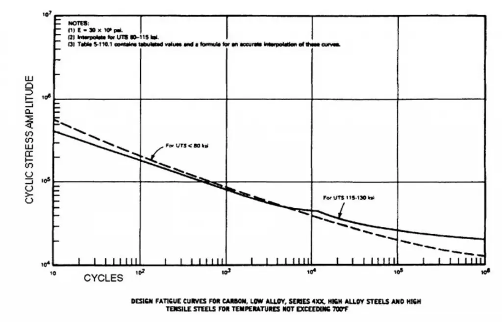
A curve is plotted by performing fatigue tests on various stress levels and finding the number of cycles to failure. This curve is popular as the S-N curve. Various codes (ASME, BS, CEN, etc) provides the S-N curve in logarithmic scale from where for a specified stress level the number of cycles till failure can be easily determined. The following figure shows a typical S-N curve from ASME Code.

Typical Fatigue curve (S-N Curve)

Predicting Metal Fatigue

Mathematical Models

Mathematical models are used to predict the fatigue life of materials based on various parameters. Some of the most common models include:

  • Miner’s Rule: This is a linear cumulative damage model that helps estimate the fatigue life based on varying stress levels.
  • Basquin’s Law: Used to predict high-cycle fatigue behavior, it relates the stress amplitude to the number of cycles to failure.

Software Tools

Advanced computational tools and simulations have become integral in predicting fatigue. Finite Element Analysis (FEA) allows engineers to simulate stress and strain distributions in complex geometries, providing insights into potential fatigue issues before physical testing.

How to Prevent Metal Fatigue?

There are various options by which metal fatigue can be minimized. Some of them are:

Proper Material Selection

Choosing the right material is crucial in mitigating fatigue. Advanced materials, such as high-strength steels and composites, often have better fatigue resistance.

Design Modifications

Implementing design changes to reduce stress concentrations, such as avoiding sharp corners and using fillets, can significantly enhance fatigue life.

Surface Treatments

Surface treatments, such as shot peening or hardening, can improve fatigue resistance by altering the surface characteristics of a material.

Regular Maintenance

Conducting regular inspections and maintenance can help detect early signs of fatigue, allowing for timely interventions and repairs.

Performing Fatigue Analysis

Metal fatigue can be prevented by following proper engineering design considerations and by performing a fatigue analysis during the design phase. In most situations, the parts that will be subjected to cyclic loadings are known beforehand during the design phase. So, using those data, fatigue analysis can be performed to find out metal fatigue capabilities. Various software programs have the capabilities to perform fatigue analysis of different components, like

  • COMSOL Multiphysics
  • nCode Design Life
  • FRANC 2D/3D
  • LIMIT stress evaluation software for fatigue analysis
  • eFatigue
  • FE-SAFE
  • MSc fatigue
  • Caesar II

To conclude, metal fatigue is a multifaceted phenomenon with significant implications across various industries. As technology advances, understanding and managing fatigue will continue to be a critical area of focus for engineers and researchers alike. By prioritizing research and development in this field, we can enhance the safety, reliability, and longevity of metal components in an increasingly demanding world.

Frequently Asked Questions: Metal Fatigue

1. What is metal fatigue?

Answer: Metal fatigue refers to the gradual and localized structural damage that occurs when a material is subjected to cyclic loading, leading to the formation and growth of cracks. This can result in sudden and unexpected failure.

2. What are the stages of metal fatigue?

Answer: Metal fatigue occurs in three stages:

  1. Crack Initiation: Small cracks form at stress concentrators or surface defects.
  2. Crack Propagation: The cracks grow with each loading cycle.
  3. Final Fracture: Eventually, the crack becomes large enough to cause complete failure of the material.

3. What factors influence metal fatigue?

Answer: Key factors include:

  • Material properties (e.g., ductility, toughness)
  • Surface finish (e.g., roughness)
  • Environmental conditions (e.g., temperature, humidity)
  • Loading conditions (e.g., type of stress—tensile or compressive)

4. How is metal fatigue tested?

Answer: Metal fatigue is commonly tested using methods such as:

  • Wöhler (S-N) curves: Testing specimens under cyclic loading to plot stress against the number of cycles to failure.
  • Strain-life (ε-N) approach: Relating strain to life for ductile materials.
  • Fracture mechanics: Predicting crack growth based on existing flaws.

5. What is a Wöhler curve?

Answer: A Wöhler curve, or S-N curve, is a graphical representation of the relationship between the cyclic stress amplitude (S) and the number of cycles to failure (N). It helps in determining the fatigue strength of materials.

6. How can metal fatigue be prevented?

Answer: Preventative measures include:

  • Selecting materials with high fatigue resistance.
  • Implementing design modifications to reduce stress concentrations.
  • Applying surface treatments (e.g., shot peening).
  • Conducting regular maintenance and inspections.

7. What industries are most affected by metal fatigue?

Answer: Metal fatigue is a concern in many industries, including:

  • Aerospace
  • Automotive
  • Civil engineering (bridges and buildings)
  • Manufacturing and machinery

8. How can I identify signs of metal fatigue?

Answer: Signs of metal fatigue may include:

  • Visible cracks or surface defects
  • Changes in color or surface texture
  • Unexpected noise or vibration in machinery
  • Reduced performance or failure of components

9. Are there any standards for fatigue testing?

Answer: Yes, organizations such as ASTM International and ISO have established standards for conducting fatigue tests, ensuring consistency and reliability in results.

10. What is the role of advanced materials in combating metal fatigue?

Answer: Advanced materials, such as high-strength alloys and composites, often exhibit better fatigue resistance. Ongoing research into new materials aims to enhance performance and reduce failure risks in applications where fatigue is a concern.

11. Can fatigue failure occur without exceeding the material’s yield strength?

Answer: Yes, metal fatigue can lead to failure even under loads that do not exceed the yield strength, as it is the repetitive nature of the loading that contributes to crack formation and growth.

The Function of Nickel in Stainless Steel: Is Nickel in Stainless Steel Harmful?

Nickel is a pure chemical element of the periodic table. It is represented by the symbol Ni and its atomic number is 28. Nickel is a transition metal in the d-block with a high boiling point (14530C). It is ductile and exhibits magnetic properties at room temperature. First discovered in the 1700s, nickel is used as a catalyst for various chemical reactions and is one of the main alloying elements in stainless steel. Nickel in Stainless Steel is a widely used constituent.

More than 66% of globally produced nickel is used to manufacture stainless steel alloy. Nickel in stainless steel improves formability, weldability, and ductility. Nickel-containing stainless steel is suitable for high-temperature applications. They provide very good corrosion resistance and remain ductile at low temperatures. In certain applications, nickel increases the corrosion resistance of stainless steel. The importance of nickel in stainless steel can be easily understood from the fact that nickel-containing stainless steel grades make up more than 75% of global stainless steel production.

Role of Nickel in Stainless Steel

There are several benefits that come with the addition of nickel in stainless steel.

The addition of Nickel increases the toughness of stainless steel. In general, chromium addition is steel decreases the toughness. So, that decrease in toughness is compensated by the addition of Nickel. Ferromagnetism in steel is not desirable in certain applications. The chromium addition induces ferromagnetism. The proper addition of Nickel helps in countering such problems.

Nickel in stainless steel work as the austenitic stabilizer. Nickel addition in steel functions to stabilize tough and ductile, FCC austenitic structure. Conventional steel has a body-centered cubic crystal known as a ferritic structure. Roughly 8% nickel can stabilize the austenitic structure at room temperature. This is the reason that most stainless steel grades (Example 304 grade) contain 8 percent nickel. In the early twentieth century, this composition (18% Chromium and 8% Nickel) was one of the first to be developed in the history of stainless steel.

In recent times, Manganese and Nitrogen is used to form austenitic structures. However, still, a small percentage of nickel is deliberately added to all the high-manganese austenitic grades commercially available today. Even the duplex stainless steel grades contain 1 percent or more nickel.

Nickel is also known to reduce the ductile-to-brittle transition temperature. This is the temperature below which the stainless steel or alloys have a tendency to convert into brittle. However, there are other parameters like grain size and other alloying elements that affect ductile-to-brittle transition temperature.

Even all high-strength precipitation-hardening stainless steel grades also contain nickel at an appreciable amount.

An increase in nickel addition in stainless steel increases the corrosion resistance. Nickel in stainless steel reduces the active corrosion rate in crevice corrosion. The following image shows the effect of increasing nickel content in reducing the corrosion rate in a 15 percent sulphuric acid solution at 80° C. However, note that various other alloying additions, too, affect the corrosion rate.

Effect of Nickel in corrosion rate modification
Fig. 1: Effect of Nickel in corrosion rate modification

Properties of Nickel Containing Stainless Steels

Nickel-containing stainless steels provide various unique properties like

  • Good weldability
  • High toughness
  • Good formability
  • High-temperature properties
  • Good Corrosion resistance
  • Good surface finish
  • Sustainability

Is nickel in stainless steel harmful?

Nickel-containing Stainless Steel is widely used in food and beverage industries for quite a long time. Easy formability, superb corrosion resistance, and excellent durability make them an ideal choice for cookware. Due to various health concerns raised over the recent past stainless steel is also believed to be harmful due to the presence of nickel in it. But studies have shown that unless the stainless steel is of poor quality, nickel will be soluted in a very small amount that is not in poisonous level to humans. So high-quality 304 or 316-grade stainless steel does not pose a severely bad effect on human health.

The following image from the U.S. National Library of Medicine shows that the amount of nickel intake due to the use of nickel-containing stainless steel is much lower than the tolerable intake limit of daily consumption.

Daily Nickel intake vs Tolerable limit
Fig. 2: Daily Nickel intake vs Tolerable limit

The Melting Points of Metals | Melting Point of Metals Chart

Metals are popular and widely used because of their capability to withstand extreme conditions. Sustaining high temperature is one such ability. Furnaces, ignition nozzles, high-speed machinery, combustion engines, jet engines, and exhaust systems are consistently working at high temperatures that can cause the melting of certain materials. Hence, the melting temperature of metals is a selection criterion when choosing materials for high-temperature applications. So, the melting temperature of metals must be known prior to use in a specific application. In this article, we will explore more about the melting point temperatures of various metals and alloys.

What are the Melting Points of Metals?

A metal’s melting point temperature is defined as the lowest metal temperature at which the metal starts to transform from a solid phase into a liquid phase. Scientifically, it is known as the melting point temperature of materials. At the melting point temperature, the metal’s solid and liquid phase coexists in equilibrium. On application of more heat, the temperature will not increase till the complete solid phase transforms into the liquid phase and thereafter temperature will grow again.

Why is the Metal Melting Temperature Important?

The melting point temperature of a metal is one of the most important considerations for various industries as stated below:

  • In the casting industry where the end product is manufactured in foundry shops by melting the metal and pouring that liquid metal into various cast forms. So, information regarding those metals’ melting point temperature must be known to heat that metal or alloy for liquefication.
  • The melting temperature of metals and alloys is an important parameter for metallic modifications, the production of new alloys, laboratory experimentation, etc in metallurgical industries.
  • Heat treatment of metals and alloys also requires information about the melting temperature of that material so that it is not heated till melting.
  • High-temperature applications should use metals with high melting points. So material selection also requires information related to melting point temperature.
  • Welding of materials needs the data for metal’s melting point temperature.

Melting Points of Metals and Alloys

Melting Point of Steel:

The melting point of steel depends on the type of steel. This alloy contains traces of other alloying elements that are added purposely to improve its corrosion resistance, ease of fabrication, and strength. Depending on the presence and percentage of alloying elements, the melting point of steel varies. In general, steel’s melting point is around 1370°C (2500°F) but it varies within a range. Let us explore the melting point of steel with the below-mentioned five main types of steel:

Melting Point of Carbon Steel: Low Carbon Steel contains carbon (0.05 to 0.15 wt%), copper (0.6%), manganese (1.65%), and silicon (0.6%). The melting point of low carbon steel is 1410°C (2570°F).
High carbon steel containing 0.3 to 1.7 wt% of carbon has melting points ranging from 1425-1540°C (2600-2800°F).

The melting point of Stainless Steel: The melting point of stainless steel containing 10.5% to 11 wt% chromium is 1510°C (2750°F). The melting point of Stainless Steel grade 304 ranges from 1400-1450°C; grade 316 ranges from 1375-1400°C; and grade 321 ranges from 1400-1425°C. The melting point of DSS grade 2205 ranges from 1385-1440°C. The melting points of other stainless steel grades are:

  • Grade 430: 1425-1510°C (2597-2750°F)
  • Grade 316: 1375-1400°C (2507-2552°F)
  • Grade 434: 1426-1510°C (2600-2750°F)
  • Grade 420: 1450-1510°C (2642-2750°F)
  • Grade 304: 1400-1450°C (2552-2642°F)
  • Grade 410: 1480-1530°C (2696-2786°F)

Melting Point of Maraging Steel: Maraging steel is a low carbon-iron alloy, having 15 to 25 wt% nickel as its main alloying element. The melting point of maraging steel is 1413°C (2575°F).

Melting point of Alloy Steel: Alloy steels containing 1 to 50 wt% of the alloying element are known as alloy steel. There are two groups of alloy steels: low alloy steels and high alloy steels. The melting point of low alloy steel is 1432°C (2610°F) and the same for high alloy steel is 1415°C (2600°F).

Melting point of Tool Steel: The hardest variety of Steels, Tool Steels contains 0.7 to 1.4 wt% Carbon and manganese, chrome, nickel, tungsten, molybdenum, phosphorous, and sulfur in various proportions as alloying elements. The melting point of tool steel varies in the range of 1400 to 1425°C (2550 to 2600°F).

Melting point of other Metals: Metal’s Melting Point Chart

The melting point of metals chart is provided below in a tabular format:

MetalMelting Point (0C)Melting Point (0F)
Actinium10501922
Admiralty Brass900 – 9401650 – 1720
Aluminum6601220
Aluminum Alloy463 – 671865 – 1240
Aluminum Bronze1027 – 10381881 – 1900
Antimony6301170
Babbitt249480
Beryllium12852345
Beryllium Copper865 – 9551587 – 1750
Bismuth271.4520.5
Brass, Red10001832
Brass, Yellow9301710
Cadmium321610
Chromium18603380
Cobalt14952723
Copper10841983
Cupronickel1170 – 12402140 – 2260
Gold, 24K Pure10631945
Hastelloy C1320 – 13502410 – 2460
Inconel1390 – 14252540 – 2600
Incoloy1390 – 14252540 – 2600
Iridium24504440
Iron, Wrought1482 – 15932700 – 2900
Iron, Gray Cast1127 – 12042060 – 2200
Iron, Ductile11492100
Lead327.5621
Magnesium6501200
Magnesium Alloy349 – 649660 – 1200
Manganese12442271
Manganese bronze865 – 8901590 – 1630
Mercury-38.86-37.95
Molybdenum26204750
Monel1300 – 13502370 – 2460
Nickel14532647
Niobium (Columbium)24704473
Osmium30255477
Palladium15552831
Phosphorus44111
Platinum17703220
Plutonium6401180
Potassium63.3146
Red Brass990 – 10251810 – 1880
Rhenium31865767
Rhodium19653569
Ruthenium24824500
Selenium217423
Silicon14112572
Silver, Coin8791615
Silver, Pure9611761
Silver, Sterling8931640
Sodium97.83208
Tantalum29805400
Thorium17503180
Tin232449.4
Titanium16703040
Tungsten34006150
Uranium11322070
Vanadium19003450
Yellow Brass905 – 9321660 – 1710
Zinc419.5787
Zirconium18543369
The melting point of metals chart