Nickel is a pure chemical element of the periodic table. It is represented by the symbol Ni and its atomic number is 28. Nickel is a transition metal in the d-block with a high boiling point (14530C). It is ductile and exhibits magnetic properties at room temperature. First discovered in the 1700s, nickel is used as a catalyst for various chemical reactions and is one of the main alloying elements in stainless steel. Nickel in Stainless Steel is a widely used constituent.
More than 66% of globally produced nickel is used to manufacture stainless steel alloy. Nickel in stainless steel improves formability, weldability, and ductility. Nickel-containing stainless steel is suitable for high-temperature applications. They provide very good corrosion resistance and remain ductile at low temperatures. In certain applications, nickel increases the corrosion resistance of stainless steel. The importance of nickel in stainless steel can be easily understood from the fact that nickel-containing stainless steel grades make up more than 75% of global stainless steel production.
Role of Nickel in Stainless Steel
There are several benefits that come with the addition of nickel in stainless steel.
The addition of Nickel increases the toughness of stainless steel. In general, chromium addition is steel decreases the toughness. So, that decrease in toughness is compensated by the addition of Nickel. Ferromagnetism in steel is not desirable in certain applications. The chromium addition induces ferromagnetism. The proper addition of Nickel helps in countering such problems.
Nickel in stainless steel work as the austenitic stabilizer. Nickel addition in steel functions to stabilize tough and ductile, FCC austenitic structure. Conventional steel has a body-centered cubic crystal known as a ferritic structure. Roughly 8% nickel can stabilize the austenitic structure at room temperature. This is the reason that most stainless steel grades (Example 304 grade) contain 8 percent nickel. In the early twentieth century, this composition (18% Chromium and 8% Nickel) was one of the first to be developed in the history of stainless steel.
In recent times, Manganese and Nitrogen is used to form austenitic structures. However, still, a small percentage of nickel is deliberately added to all the high-manganese austenitic grades commercially available today. Even the duplex stainless steel grades contain 1 percent or more nickel.
Nickel is also known to reduce the ductile-to-brittle transition temperature. This is the temperature below which the stainless steel or alloys have a tendency to convert into brittle. However, there are other parameters like grain size and other alloying elements that affect ductile-to-brittle transition temperature.
Even all high-strength precipitation-hardening stainless steel grades also contain nickel at an appreciable amount.
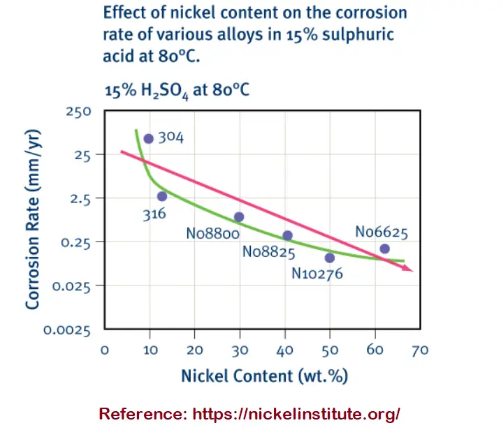
An increase in nickel addition in stainless steel increases the corrosion resistance. Nickel in stainless steel reduces the active corrosion rate in crevice corrosion. The following image shows the effect of increasing nickel content in reducing the corrosion rate in a 15 percent sulphuric acid solution at 80° C. However, note that various other alloying additions, too, affect the corrosion rate.
Fig. 1: Effect of Nickel in corrosion rate modification
Properties of Nickel Containing Stainless Steels
Nickel-containing stainless steels provide various unique properties like
Good weldability
High toughness
Good formability
High-temperature properties
Good Corrosion resistance
Good surface finish
Sustainability
Is nickel in stainless steel harmful?
Nickel-containing Stainless Steel is widely used in food and beverage industries for quite a long time. Easy formability, superb corrosion resistance, and excellent durability make them an ideal choice for cookware. Due to various health concerns raised over the recent past stainless steel is also believed to be harmful due to the presence of nickel in it. But studies have shown that unless the stainless steel is of poor quality, nickel will be soluted in a very small amount that is not in poisonous level to humans. So high-quality 304 or 316-grade stainless steel does not pose a severely bad effect on human health.
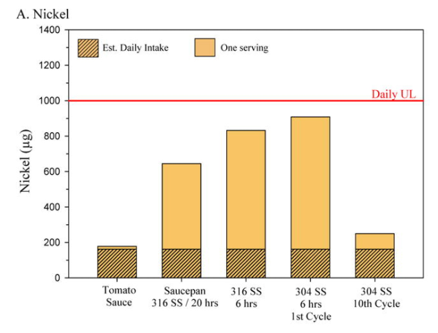
The following image from the U.S. National Library of Medicine shows that the amount of nickel intake due to the use of nickel-containing stainless steel is much lower than the tolerable intake limit of daily consumption.
Fig. 2: Daily Nickel intake vs Tolerable limit
The Melting Points of Metals | Melting Point of Metals Chart
Metals are popular and widely used because of their capability to withstand extreme conditions. Sustaining high temperature is one such ability. Furnaces, ignition nozzles, high-speed machinery, combustion engines, jet engines, and exhaust systems are consistently working at high temperatures that can cause the melting of certain materials. Hence, the melting temperature of metals is a selection criterion when choosing materials for high-temperature applications. So, the melting temperature of metals must be known prior to use in a specific application. In this article, we will explore more about the melting point temperatures of various metals and alloys.
What are the Melting Points of Metals?
A metal’s melting point temperature is defined as the lowest metal temperature at which the metal starts to transform from a solid phase into a liquid phase. Scientifically, it is known as the melting point temperature of materials. At the melting point temperature, the metal’s solid and liquid phase coexists in equilibrium. On application of more heat, the temperature will not increase till the complete solid phase transforms into the liquid phase and thereafter temperature will grow again.
Why is the Metal Melting Temperature Important?
The melting point temperature of a metal is one of the most important considerations for various industries as stated below:
In the casting industry where the end product is manufactured in foundry shops by melting the metal and pouring that liquid metal into various cast forms. So, information regarding those metals’ melting point temperature must be known to heat that metal or alloy for liquefication.
The melting temperature of metals and alloys is an important parameter for metallic modifications, the production of new alloys, laboratory experimentation, etc in metallurgical industries.
Heat treatment of metals and alloys also requires information about the melting temperature of that material so that it is not heated till melting.
High-temperature applications should use metals with high melting points. So material selection also requires information related to melting point temperature.
Welding of materials needs the data for metal’s melting point temperature.
Melting Points of Metals and Alloys
Melting Point of Steel:
The melting point of steel depends on the type of steel. This alloy contains traces of other alloying elements that are added purposely to improve its corrosion resistance, ease of fabrication, and strength. Depending on the presence and percentage of alloying elements, the melting point of steel varies. In general, steel’s melting point is around 1370°C (2500°F) but it varies within a range. Let us explore the melting point of steel with the below-mentioned five main types of steel:
Melting Point of Carbon Steel: Low Carbon Steel contains carbon (0.05 to 0.15 wt%), copper (0.6%), manganese (1.65%), and silicon (0.6%). The melting point of low carbon steel is 1410°C (2570°F). High carbon steel containing 0.3 to 1.7 wt% of carbon has melting points ranging from 1425-1540°C (2600-2800°F).
The melting point of Stainless Steel: The melting point of stainless steel containing 10.5% to 11 wt% chromium is 1510°C (2750°F). The melting point of Stainless Steel grade 304 ranges from 1400-1450°C; grade 316 ranges from 1375-1400°C; and grade 321 ranges from 1400-1425°C. The melting point of DSS grade 2205 ranges from 1385-1440°C. The melting points of other stainless steel grades are:
Melting Point of Maraging Steel: Maraging steel is a low carbon-iron alloy, having 15 to 25 wt% nickel as its main alloying element. The melting point of maraging steel is 1413°C (2575°F).
Melting point of Alloy Steel: Alloy steels containing 1 to 50 wt% of the alloying element are known as alloy steel. There are two groups of alloy steels: low alloy steels and high alloy steels. The melting point of low alloy steel is 1432°C (2610°F) and the same for high alloy steel is 1415°C (2600°F).
Melting point of Tool Steel: The hardest variety of Steels, Tool Steels contains 0.7 to 1.4 wt% Carbon and manganese, chrome, nickel, tungsten, molybdenum, phosphorous, and sulfur in various proportions as alloying elements. The melting point of tool steel varies in the range of 1400 to 1425°C (2550 to 2600°F).
Melting point of other Metals: Metal’s Melting Point Chart
The melting point of metals chart is provided below in a tabular format:
Wastewater treatment is a process to treat sewage or wastewater to remove suspended solid contaminants and convert them into effluent that can be discharged back to the environment with acceptable impact. The plants where the wastewater treatment process takes place are popularly known as Wastewater treatment plants, Water resource recovery facilities, or Sewage Treatment Plants. Pollutants present in wastewater can negatively impact the environment and human health. So, these must be removed, broken down, or converted during the treatment process. Typical pollutants that are normally present in wastewater are:
Bacteria, viruses, and disease-causing pathogens.
helminths (intestinal worms and worm-like parasites)
Toxic Chlorine compounds and inorganic chloramines.
Metals possessing toxic effects like mercury, lead, cadmium, chromium, and arsenic.
Decaying organic matter and debris.
oils and greases.
Toxic chemicals like PCBs, PAHs, dioxins, furans, pesticides, phenols, etc.
Some pharmaceutical and personal care products.
How is wastewater formed?
A number of activities help in the formation of wastewater. Domestic wastewater is generated because of activities like bathing, washing, using the toilet, etc in residences, restaurants, and businesses. Surface rainwater runoff is generated due to the mixing of debris, grit, nutrients, and various chemicals. Industrial wastewater results because of chemical and manufacturing industry discharges. So, wastewater is essentially the used water that has been affected by domestic, commercial, or industrial use.
Domestic wastewater is relatively easy to treat as compared to industrial wastewater due to its high-strength nature.
Wastewater Treatment Process
The sequence of wastewater treatment processes is usually characterized as:
Preliminary treatment
Primary treatment
Secondary treatment
Tertiary treatment or Advanced treatment
Preliminary treatment:
Preliminary wastewater treatment precedes primary treatment. Its main function is to minimize operational problems and to protect subsequent treatment units. The major processes that are used during the preliminary wastewater treatment process are Equalization, Neutralization, Temperature adjustment, Screening, Grit removal, etc.
Primary treatment:
The primary wastewater treatment process is the physical or chemical treatment for the removal of materials that will either float or readily settle out by gravity. The major processes used in this step are Sedimentation and Dissolved air floatation. Suspended solid materials from the wastewater are removed by the sedimentation primary treatment. Other floatable materials like oils, fats, etc are removed using dissolved air floatation treatment. Primary wastewater treatment, in general, removes about 60% of suspended solids from wastewater.
Secondary treatment:
Secondary wastewater treatment uses biological and chemical means for the substantial elimination of dissolved organics and colloidal materials. The processes used in the secondary treatment are Activated sludge, Aerated Pond, Aerobic-anaerobic ponds, Trickling filter, Chemical oxidation, Chemical mixing flocculation and clarification, Gravity filtration, Dissolved-air flotation with chemicals, Pressure filtration, Anaerobic contact, etc. Secondary wastewater treatment is capable of removing more than 90 percent of suspended solids.
Advanced treatment:
Advanced wastewater treatment is used to remove pollutants by methods other than those used in conventional treatment methods mentioned above. The advanced wastewater treatment process employs a number of different unit operations like Activated carbon adsorption, Micro straining filtration, ponds, post-aeration, Land treatment, membrane solids separation, and specific treatment processes such as phosphorus and nitrogen removal, etc.
Very high effectiveness is the characteristic of the Advanced wastewater treatment process. That’s why this method is employed to meet strict effluent standards. For example, Phosphorus levels of less than 1 milligram per liter and total nitrogen levels of 5.0 milligrams per liter or less can be maintained through an advanced wastewater treatment process.
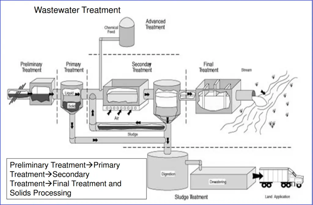
Fig. 1: Schematic of Basic Wastewater Treatment Processes
Basic Design Considerations
Wastewater Treatment Requirement: The requirement of wastewater treatment is dependent on the following parameters:
the influent characteristics,
the effluent quality requirements, and
the wastewater treatment processes that produce an acceptable effluent.
Laboratory tests of wastewater samples are performed to find out influent characteristics. Effluent quality requirements are fixed by Federal, interstate, State, and other local regulatory agencies. Wastewater Treatment processes are then decided according to influent-effluent constraints and economic and technical considerations.
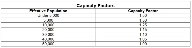
The Capacity of Wastewater Treatment: The capacity of wastewater treatment is decided based on the design population and multiplying it with the proper capacity factor. Design population is found by adding total residents with 1/3 the non-resident populations. The following image (Fig. 2) provides a sample table of capacity factors with respect to effective population.
Fig. 2: Capacity Factors with respect to Effective Population
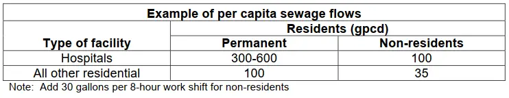
Future service demand calculation: Per capita waste loads of a community are decided based on the nature of the activities as different activities have different water uses. The table in Fig. 3 provides a typical example of sewage flows in gallons per capita per day (gpcd).
Fig. 3: Per capita sewage flow example
Estimating the volume of wastewater:
The required average daily wastewater flow for the design of new wastewater treatment plants needs to be calculated by multiplying the design population by the per capita rates of flow as determined from the table in Fig. 3.
To calculate contributing populations, a factor of 3.6 persons per family residential unit can be considered. For hospitals, the calculation can be done by counting the number of beds, plus the number of hospital staff eating three meals at the hospital, plus the number of shift employees having one meal there. This total is the number of residents to be used in the design calculations. The capacity factor still needs to be applied while calculating design populations. To find the volume of industrial flow, actual measurements can be done to ascertain the flow rates. Typical industrial discharges include wastewater from the following:
wastewater treatment plant itself;
vehicle wash areas;
maintenance facilities;
swimming pool backwash water;
weapons cleaning buildings;
boiler blowdowns;
photographic laboratory;
water treatment plant backwash;
cooling tower blowdown;
fire fighting facility;
medical or dental laboratories.
When significant inflow enters the sewer system, storm-water flows should be included in wastewater treatment plant design.
Once, all the above data is calculated, the following equation is used to estimate the total anticipated flow to the sewage plant:
x = a + b
Where x = Total flow to sewage plant a = Flow from population (effective population × 100 gpcd × capacity factor) b = Infiltration + industrial wastewater + storm-water (4 × dry-weather flow)
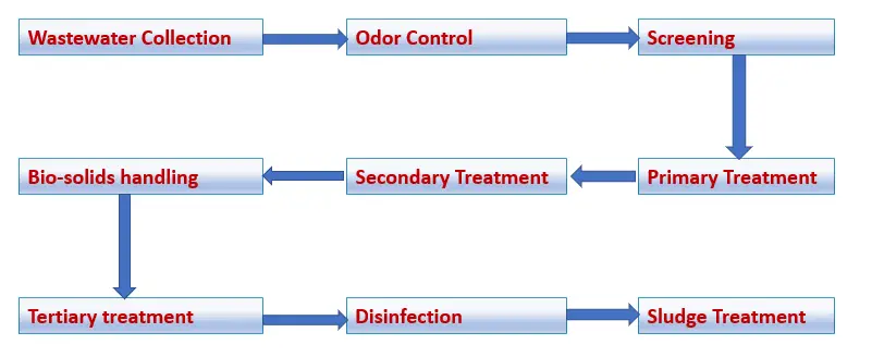
The following image (Fig. 4) provides a typical flowchart for Wastewater treatment processes.
Fig. 4: Flowchart for Wastewater treatment processes
Types of Wastewater Treatment Plants
For the betterment of society, the environment, and the future, wastewater treatment should be taken seriously. The outbreak of numerous waterborne diseases can be prevented by proper wastewater treatment. So, Wastewater treatment plants play a major role in keeping the environment clean and saving numerous lives. There are basically three types of Wastewater treatment plants:
Effluent Treatment Plants
Sewage Treatment Plants, and
Combined Effluent Treatment Plants
Effluent Treatment Plants are used by major chemical, leather, and pharmaceutical companies to purify water and remove dirt, grit, pollution, toxic, and non-toxic materials, polymers, etc. The typical processes used by Effluent Treatment Plants are centrifuging, filtration, incineration for chemical processing, and effluent treatment.
Sewage treatment plants eliminate contaminants from wastewater and household sewage. It uses physical, chemical, and biological processes to remove physical, chemical, and biological contaminants to make water and solid waste reusable.
Combined Effluent Treatment Plants are established where a cluster of small-scale industries is present. Such facilities reduce the cost of a single company while preventing pollution.
Top Online Courses on Wastewater Treatment
Wish to know more about waste-water treatment! Then the following video courses are for you. Click on the subject below and review the details and then proceed to take the course.
A framework agreement can be defined as an agreement between two or more business organizations (contracting parties or suppliers) that recognizes the agreement on enough matters to move forward with the relationship, with more details that will be agreed to in the future. However, this is not a final agreement on all matters relevant to the relationship between them. In a framework agreement, the governing terms and conditions for any future contracts with regard to the price, service levels, quality, scope, and quantity are normally established for the duration of the agreement.
Such agreements create a long-term relationship with the parties to carry out work mutually. Setting up a framework agreement between organizations is a highly efficient way of working together. The actual tendering process and the time taken for those processes can be saved. In a framework agreement, work is normally awarded to a bidder after running a mini-competition. This reduces the time required and the complexity of those works. Framework arrangements are a very convenient mechanism used widely to establish a suitable trading relationship between organizations.
As Framework arrangements represent a ‘smarter’ way of purchasing as compared to placing ‘one-off’ orders for recurrent contracts, It is becoming more popular. A buyer simply uses the agreement and issue a separate order considering the term and conditions of the framework agreements. Framework agreements are also known as ‘trading agreements’, ‘standing offers’, ‘umbrella agreements’, or ‘blanket orders’.
Framework Agreement
Why use a framework agreement?
A framework agreement is a useful way of obtaining goods and services that are regularly or periodically required. It allows the purchaser to aggregate the future, anticipated requirements and thereby improve the purchaser’s negotiating position based on the likely economies of scale. In addition to the savings in cost, framework agreements also save time and effort by eliminating the need to run separate competitive tendering exercises for each requirement.
In framework agreements, the client/procurer asks a large number of firms (for example 20 firms) to submit details of their ability in terms of various qualitative factors (like experience, capability, safety qualifications, cost, etc) and then selects a small number of firms (normally 2-5) tenderers, to be in that framework. All subsequent jobs are then allocated by conducting a ‘mini-tender with this small number of firms and finally awarded to the most effective bidder in terms of cost and capability.
Duration of a framework agreement
The time duration for a framework agreement depends on the buyer or the client. Normally it can vary in between 2 years to 10 years.
Advantages of a framework agreement
A framework agreement is a great way to work between organizations. All the parties under the agreement get several benefits like:
It nourishes a long-term relationship.
The project or work awarding process becomes simple and less time-consuming. No need for numerous proposal preparation.
Process and contract terms are defined beforehand so it is not required to decide for each individual project or job.
Future jobs are known beforehand so easy for planning.
Possibility of being awarded multiple contracts.
Competitive pricing and on-time delivery.
Enables the use of e-procurement/portals by putting the suppliers’ offerings under the framework arrangement on a system accessible by all to use.
A planned approach reduces administration time and costs, thus increasing profit for all parties.
More flexibility of working.
Less downtime between identifying a need and fulfilling it
Potentially reduce the need for repeated requisitions and approvals to be processed.
Eliminates the need to carry out separate procurement exercises every time.
Good technical service with reliable quality.
However, the main rationale behind using a framework agreement is to achieve cost savings by creating economies of scale, as well as by reducing the administrative burden of issuing multiple tenders. That’s why central purchasing bodies use framework agreements as the main tool.
Disadvantages of a framework agreement
As the Framework agreement is based on future implementation, it is full of risks and uncertainties.
A framework agreement being a long-term contract, new potential suppliers or SME companies do not get access to offer their services. Also, Suppliers unsuccessful at the selection stage are locked out of any call-offs for the duration of the agreement.
Bigger Contracts.
Even after awarding the framework, still, hard work and networking are required to win specific jobs. No guarantee of business even if you’re selected as an approved supplier.
Framework agreement process
Normally, there are three steps for a framework agreement process to work effectively. Those are
1. Consideration for Framework Agreement:
The type of framework is determined by taking into consideration of the circumstances, risks, economic environment, etc. All required information is provided for example:
A description of the purpose and scope of the arrangement
Clearly state whether it is a contract or agreement
Stipulate the terms and conditions that apply to each call-off
Define the requirements – specifications, standards, Service Level Agreement (SLA)
Identify the pricing mechanism
Outline the call-off mechanism/procedure
State the term or duration of the arrangement
Identify any limitations on the use of the arrangement
If appropriate, provide a realistic estimate of volumes
2. Establishing framework agreements
When considering how many suppliers to award a framework arrangement to it may be necessary to consider the potential geographical coverage or, for a multi-disciplinary requirement, the specific components in the scope may need to be considered and broken down, and awarded separately. Another consideration may be to allow suppliers to subcontract work, but it should be made clear that in the terms and conditions that the main supplier awarded any work shall remain totally liable for their sub-contractor’s performance.
When tendering frameworks, the tender documentation should clearly state that our intention is to establish a framework arrangement; stating the duration of such arrangement; indicate the estimated maximum number of suppliers; potentially identifying the estimated total value and an outline of the award criteria.
3. Monitoring framework arrangements
Frameworks agreements and contracts with suppliers need to be properly managed, through regular performance reviews with the supplier and should consider the supplier’s performance, any pre-agreed remedial actions, and continuous improvement as well as include feedback from the key business users and the suppliers themselves.
The performance should be measured in line with the agreed metrics in the terms and conditions when the agreement was first established or re-let. The definition of the metrics and management information should be clear and include all aspects that are important (e.g. delivery performance; minimum system up-time etc.) and state which party will capture the metrics. Often, the supplier is in the best position to do this.
Difference between Framework Agreements and Framework Contracts
Often, Framework agreements are mistakenly referred to as ‘contracts’. But there are distinct differences between the two. A contract is a legally binding agreement between two parties that commits them to exchange goods and/or services in return for money. Whereas, a framework agreement is a different concept. In general, this does not include a legally binding commitment on the customer to receive any of the goods/services and to make payment. Framework agreements only give the outline terms and conditions through which the customer can place one or more individual orders, only then is there a contract between the customer and the supplier. The major differences between a framework agreement and a framework contract are:
Framework Agreement
Framework Contract
This is a consideration/arrangement for future contracts with stipulated terms and conditions.
This is the actual contract for a specified period.
Normally, money is not involved at this stage. No up-front fee payment.
Money is involved.
Not legally binding
Legally binding.
The amount of work or supply is not specified
Volume is specified.
The framework agreement is the main contract.
Framework contracts are each individual mini-contracts.
Framework Agreement vs Framework Contract
Online Courses on Procurement and Framework Agreement
If you are interested to learn more about the subject then the following course will help you. Kindly click on the subject, review the course and then join to proceed with this course:
An MSDS or Material Safety Data Sheet is a technical document containing detailed and comprehensive information on the potential hazards related to health, fire, reactivity, emergency, and environmental issues. MSDS is an essential health and safety program that focuses on safe working with chemicals, hazardous materials, medical waste, or other toxic materials. The material data sheet provides all the hazard or safety information on the storage, use, handling, and emergency procedures of the material. These are mostly prepared by the manufacturer or supplier of the product and tell about the hazardous effects of the chemical, their safe usage procedure, handling information in case of accidents, etc. MSDS follows the requirements of WHMIS (Workplace Hazardous Materials Information System) legislation, Canada, and OSHA’s Hazard Communication Standards (HCS). The main purpose of this document is to assist employees in understanding and interpreting this type of information.
As per the requirement of the Hazard Communication Standard (HCS), the manufacturer, distributor, or importer of chemical products should provide Material Safety Data Sheets for each hazardous chemical to all downstream users. These MSDSs are specific to each individual chemical covering all reasonably anticipated uses of the material. The information furnished in an MSDS is normally general in nature but is organized into either 9 or 16 sections.
Suppliers and Employers’ Responsibilities related to MSDS
It is the responsibility of the chemical suppliers to obtain or develop an MSDS for each product to be used in the workplace. They must ensure that the MSDS for the specific product contains the latest information during the time of sale (not older than 3 years).
Similarly, the employer should confirm that he receives an up-to-date latest MSDS from the supplier. They should maintain the MSDSs and ensure that a copy of the same is readily available for the workplace. They need to train their employees regarding the procedures of safe use, storage, handling, and disposal of those chemicals.
Difference between MSDS and SDS
Safety Data Sheet or SDS is the latest updated form of earlier MSDS. This transition from MSDS to SDS came into effect from May 2012 onwards. The main differences between SDS and MSDS are
SDS format provides more in-depth information as compared to MSDS and consists of sixteen sections providing specific information using a standardized classification method. Earlier MSDS used to have nine categories which have been replaced by 16 sections in SDS.
MSDS was mainly meant for Canada whereas SDS is applicable on a global level following a Globally Harmonized System of Classification and Labelling of Chemicals (GHS).
By changing from MSDS to SDS, information is now produced in a standardized, user-friendly way.
With respect to the legal implications, An SDS adheres to all of the major regulations on hazardous materials and is a safer document to use.
Contents of an MSDS
MSDS formats can vary from source to source within a country depending on national requirements. However, A material safety data sheet is normally organized into sixteen sections. Sections 1 through 8 give general information regarding the chemical, its identification, composition, hazards, safe handling practices, and emergency control measures. While Sections 9 through 11 and 16 contain other relevant scientific and technical information. An MSDS is reviewed every three years.
MSDS Categories
There are nine categories in an MSDS that include the following:
MSDS Category 1-Product Information: product identifier (name), manufacturer and supplier names, addresses, and emergency phone numbers.
MSDS Category 2-Hazardous Ingredients.
MSDS Category 3-Physical Data.
MSDS Category 4-Fire or Explosion Hazard Data
MSDS Category 5-Reactivity Data: information on the chemical instability of a product and the substances it may react with.
MSDS Category 6-Toxicological Properties: health effects.
MSDS Category 7-Preventive Measures.
MSDS Category 8-First Aid Measures.
MSDS Category 9-Preparation Information: who is responsible for the preparation and date of preparation of MSDS.
SDS Sections
There are sixteen sections of any SDS. Those are:
SDS Section 1- Product and Company Identification: In this section, the product identifier of the hazardous substance and its recommended uses are mentioned. It must also include the name, address, and contact information of the manufacturer, importer, or other responsible parties.
SDS Section 2- Hazards Identification: The Hazards Identification section warns about the different ways of that chemical exposure and the harmful effects that it can have.
SDS Section 3- Composition/information on ingredients: This section provides information on the composition of the substance and trade secret claims associated with it.
SDS Section 4- First-Aid Measures: Necessary first aid information on accidental exposure of the chemical is mentioned in this section.
SDS Section 5- Fire-Fighting Measures: Recommendations for fire events caused by the chemical are provided in this section.
SDS Section 6- Accidental Release Measures: This SDS section provides guidance to minimize exposure to people or assets due to accidental spills, leaks, or releases.
SDS Section 7- Handling and Storage: Safe handling and storage recommendations are detailed in this SDS section.
SDS Section 8- Exposure Controls/Personal Protection: To minimize worker exposure, this SDS section provides information on the exposure limits, engineering controls, and personal protective measures.
SDS Section 9- Physical and Chemical Properties: Various physical properties like Appearance, pH, Odor, Flammability, Flash Point, Density, Viscosity, Ignition temperature, etc are mentioned in this section of the SDS.
SDS Section 10- Stability and Reactivity: Data related to the chemical stability and reactivity hazards of the chemical is described in this section.
SDS Section 11- Toxicological Information: Toxilogical and health impacts are mentioned in this section.
SDS Section 12- Ecological Information: This section guides the information on the environment in case of the release of the chemical.
SDS Section 13- Disposal Considerations: To reduce potential exposure, this section suggests proper disposal practices and safe handling methods.
SDS Section 14- Transport Information: Information related to transport hazard class, packing group number, bulk transportation, precautionary measures, etc are mentioned in this section.
SDS Section 15- Regulatory Information: Safety, health, and environmental regulations of the specific chemical is identified in this section.
SDS Section 16- Other Information: Information related to manufacturing dates, revisions, or any other useful information is added in this SDS section
Safety Data Sheets must be provided for:
Chemicals (substances and mixtures) that are considered hazardous in accordance with Regulation (EC) No 1272/2008.
Substances that meet the criteria as persistent, bio-accumulative, and toxic (PBT) or very persistent very bio-accumulative (vPvB) to the environment in accordance with REACH
Substances that appear on ECHA’s Candidate List of substances of very high concern (SVHC) for a reason other than either of the two points above
Mixtures (upon request of the downstream user/ distributor) which themselves are not classified under CLP but which contain at least one substance that is:
classified as hazardous to health or the environment above concentration limits set out in Article 31(3) of REACH;
a PBT or vPvB at a concentration ≥0.1% w/w;
on the Candidate List of SVHCs at a concentration ≥0.1% w/w for a reason other than either of the two points above;
assigned an EU limit value for exposure at the workplace (OELV).
What is in an MSDS?
A Material Safety Data Sheet or MSDS lists the hazardous ingredients present in a product. It provides a detailed report of the physical and chemical characteristics of a product and its effect on human health. MSDS also lists the chemicals which adversely react with the product. The precautions that need to be exercised while handling the product and the types of measures required to be used to control exposure, emergency, and first aid procedures, etc are also presented in an MSDS.
How do I get MSDS sheets?
MSDS related to the purchased product must be supplied by the manufacturer. In general, there are two options to get an MSDS. They are:
An MSDS in form of a paper copy or e-mail attachment can be sent along with the product.
Manufacturers can upload the MSDS to their websites for users to download from there.
Why is MSDS so important?
An MSDS is very important as it provides detailed information about the potential hazard that the product may cause. Knowing all such hazards beforehand will increase safety at the workplace.
Who is responsible for safety data sheets?
As per the Hazard Communication Standard, chemical manufacturers, distributors, or importers are responsible for providing the safety data sheets to the buyer.
Are MSDS required for all chemicals?
An MSDS is required for all potentially hazardous chemicals. However, if the chemical is not hazardous, it may be exempted. In general, all chemicals used at worksites that have any potential to cause hazards must have an MSDS.
Where can I get MSDS sheets online?
The online website of VelocityEHS contains the safety datasheets of all industry-leading chemicals. You can visit their website https://www.ehs.com/resources/sds-search/ and search as SDS using the product name, manufacturer, CAS, or Product Code.
Is MSDS required for shipping?
Yes, for all potentially dangerous items, an MSDS must be provided for every single shipment.
Why is it important to know your safety data sheet?
Knowing SDS is important because one must know the hazards of the products he is using. It will help him to protect himself during emergency situations.
What are the 4 main purposes of an SDS?
An SDS serves four main purposes. They are:
Product and Supplier identification.
Identification of the potential hazard related to the product.
Prevention, and
Response.
When should you read an SDS?
The SDS must be reviewed at least once every 5 years. It must add any new data as soon as they are available.
When did MSDS change SDS?
Effective from June 1, 2015, all Material Safety Data Sheets (MSDS) of potentially hazardous products are changed with new Safety Data Sheets (SDS).
How long do you need to keep SDS sheets?
OSHA standard, 29 CFR 1910.1020, requires all employee exposure records to be maintained for at least 30 years.
Online Courses on MSDS and Safety
To learn more details about MSDS and Safety you can opt for the following courses. Click on the subject below and review the course first and then enroll in the course.
Piping Installation or Erection refers to the laying of the piping system and its related accessories to make it ready for fluid transfer. Proper piping installation following the codes and standards is the key to safety and good operation. It is the next step to piping fabrication, where pipe spools are made in the fabrication shop by cutting the pipes to the correct lengths and requirements. These prefabricated pipe spools are taken to the site or plant for assembly. This assembling of piping spools in the site following isometric or piping general arrangement drawings is referred to as piping erection. The piping coordinates are matched with the drawings during the piping installation.
Inputs Required for Piping Installation
Piping installation at the construction site is done following proper engineering work methods and drawings. The main inputs referred to during piping erection are:
Structure drawings [beams and channels are commonly used for the structure].
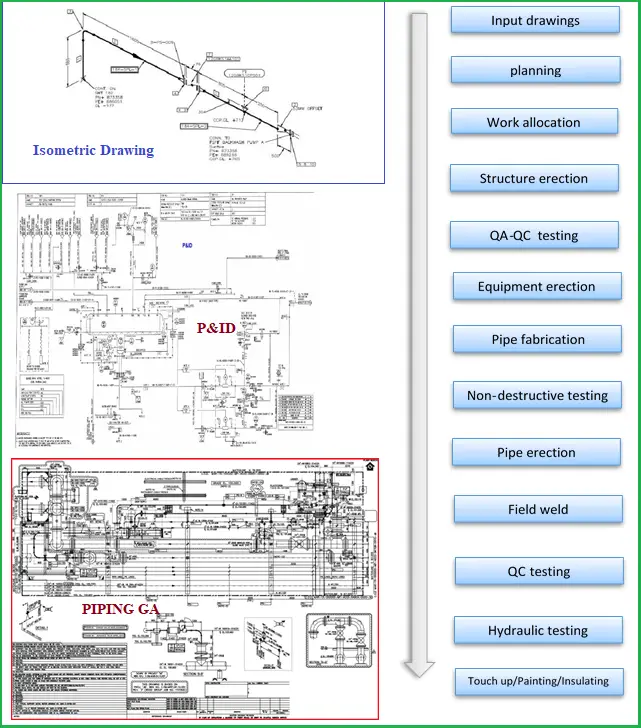
P&ID is the heart of piping; it includes pipeline number, size, material, and insulation; Process condition & physical data, operation condition, streamflow details, Equipment numbers, etc. Piping Isometric drawings include proportionate drawings with exact dimensions represented, line numbers, pipe fittings, valves, flanges, special components, tables including a list of all fittings in the drawings, etc.
Piping GA drawings include the locations of the main equipment in the plant, main piping items, fittings and valves, nozzle orientation of the concerned equipment, etc. Fig. 1 below shows typical drawings required for piping installation and a piping erection and installation flow chart.
Fig. 1: Piping Installation Flowchart and Input Drawings
Piping Installation Procedure
Piping Installation normally starts after civil supports are erected and major types of equipment are placed on the construction site. The installation of piping can be grouped into the following parts:
Pipework Erection
Installing Piping Flanges, Valve, and equipment Flange Connection
Proper planning should be made to erect piping, area-wise following piping isometric and GA drawings. The following piping erection guidelines should be followed:
All tools, equipment, ropes, and pipes must be inspected and certified by HSE guidelines before erection to ensure that they are safe and ready, clean, and free from loose contamination.
Pre-fabricated spools need to be identifiable and numbered/tagged.
Pipework should be erected on supports designated for the specific line. Primary pipe supports can be welded prior to erection following pipe support drawings. The number of temporary supports shall be minimized.
Undue stresses should not be applied to force the piping to keep it in the proper place.
To avoid the ingress of moisture and foreign matter, pipe openings should be sealed during erection.
Installation of piping on pipe racks should be done from lower elevation to higher elevation.
Pipe clearances from other pipes, equipment, and structures should be maintained.
Installing Piping Flanges
Clean pipe flanges should be brought up flush and square without forcing them to bear uniform bolt tension and gasket compression. Line items like orifice flanges, spectacle blinds, strainers, etc. shall be installed following proper orientation. A logical bolt tightening (hydraulic bolt tensioning & torque tensioning) sequence needs to be followed.
The flange connections to this equipment shall be checked for misalignment, excessive gaps, etc. Until both side flanges are ready for mating connection, flange covers shall be retained on all flanged connections to the valve or equipment.
Extra care is to be exercised for flange connections to pumps, turbines, compressors, cold boxes, air coolers, etc. Blanks or spades should be used on equipment to prevent the ingress of internal pipe debris. Bolting shall move freely through accompanying bolt holes at the right angle to the flange faces and a clear gap between the two flange faces for the gasket needs to be maintained before gasket installation.
Pipe Support Installation
Relevant pipe support detail drawings should be used for installing pipe supports.
Additional stress should not be introduced to fit the supports.
The pipe shoe should be installed at the center of the beam without any offset.
Where spring supports are required, those should be locked until hydro testing and insulation. Manufacturer installation guidelines should be followed.
Where PTFE plates are used for friction reduction, the ingress of sand in between SS and PTFE plates should be avoided.
Piping is to be arranged to facilitate pipe-supporting and shall be well-planned for ease of removal of equipment for inspection and servicing.
Pressure Testing
Following the guidelines, hydrostatic or pneumatic testing should be performed to check the system’s integrity. In case of leakage, those are repaired and re-tested again. Click here to learn more about Pressure testing
Insulation and Painting
After pressure testing, bare pipes and painted as per specification. High-temperature lines are insulated following the insulation procedure.
Marking and Identification
All pipes and fabricated fittings are marked on their outside with letters and numbers for easy identification of lines, their services, etc. Marking is normally done by stamping, tagging, stenciling, or using any other permanent marking method.
Installation of Expansion Joints
Expansion joints are normally required for critical piping systems. Bellows should be installed following the vendor’s guidelines and installation drawings. Piping should be perfectly aligned with the expansion joint as mentioned in the detailed drawings.
Vents and Drains
Ideally, vents and drains should be located in the isometric drawing or GA drawings. In case, high-point vents and low-point drains are not provided in those drawings, these should be provided as per the instructions of the Engineer-in-Charge/Job standards/ Piping Specifications.
Installing Underground Pipes
Before starting buried pipe installation, it must be ensured that trench excavation is done following the approved drawing.
Final measurements, tests, and surveys are to be completed before backfilling.
The depth of cover as mentioned in the GA drawings should be maintained.
Equipment and Tools for Pipe Erection
The following equipment and tools are used for piping erection and installation purposes.
“SAFETY FIRST” is the primary concern of engineers. Hence, the safety of the people should override all other targets and achievements. Any unsafe situation should immediately be reported to the HSE manager and the work should be postponed. So the following guidelines should always be observed during piping installation and erection.
Identifying the hazards associated with piping services. This is mainly concerned while working in operating plants.
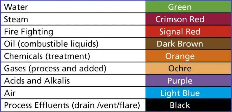
Understanding the color codes: Pipes are normally colored following standard guidelines to identify based on fluid service categories. The following image (Fig. 2) provides a sample color-coding table based on the BS 1710 standard.
Exercise extra care while tying a pipe to an operating system.
Use proper safety guidelines while working at heights and confined spaces.
Always be aware of what can go wrong and what to do if things go wrong.