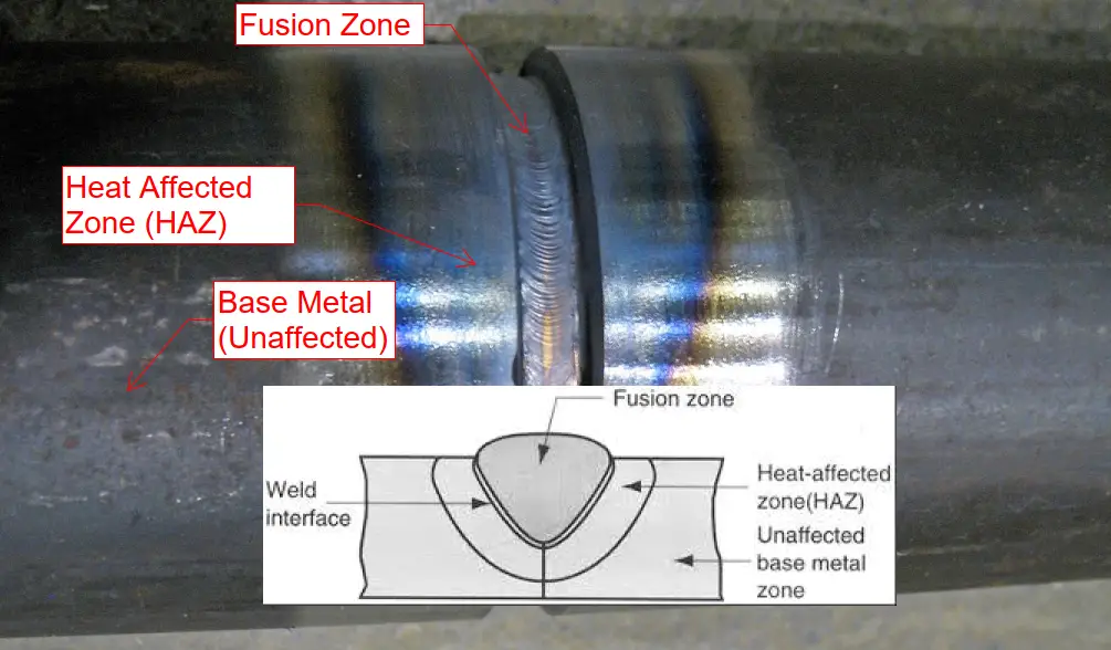
The heat-affected zone (HAZ) is an area generated when a metal is subjected to very high temperatures (Example: Welding, Mechanical Cutting, Laser Cutting, Plasma Cutting, etc). This is the non-melted zone near the exact worked area. The mechanical properties of the heat-affected zone are altered due to being exposed to high temperatures. So, the heat-affected zone or HAZ can be defined as the area between the melted metal and the base metal where microstructural changes occur. Refer to the Fig. 1 below:
Fig. 1: Explanation of Heat-Affected Zone
As can be seen from the above figure, while welding four distinct zones are created. Fusion Zone or FZ, Weld Interface, Heat Affected Zone or HAZ, and Unaffected Base Metal Zone.
The Fusion zone is a mixture of molten metal and filler metal. Next, the narrow mushy zone consisting of partially melted metal is the weld interface. The next region that suffers a peak temperature below the melting point temperature creating microstructural changes is known as the heat-affected zone. The parameters that decide the extent of microstructural changes are
Amount of heat input
Maximum temperature reached
Duration of elevated temperature, and
the cooling rate
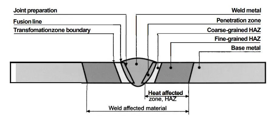
A heat-affected zone weakens the metal by reducing its mechanical strength and is the weakest section in a weldment. Depending on various factors like material properties, heat concentration, intensity, welding, or metal cutting process, the HAZ area can vary in size and severity. The nomenclature of zones and boundaries in the heat-affected zone is shown in Fig. 2.
Fig. 2: Zones and boundaries in the heat-affected zone
Causes of Heat-Affected Zone
The amount of heat input during the welding or cutting process normally exceeds the melting temperature and subsequent cooling leads to microstructural changes. Thermal diffusivity is the single most important factor influencing the size of the heat-affected zone. The level of thermal diffusivity is dependent on the metals:
Materials with high thermal diffusivity are capable of transferring the heat variation rapidly and cooling quicker, thus reducing the heat-affected zone width. On the contrary, materials with a lower thermal diffusivity coefficient retain the heat and the HAZ region becomes wider. Also, the duration of heat exposure has a direct impact on the HAZ region. When a metal is exposed to greater amounts of energy for longer periods the heat-affected zone is larger. With respect to the welding process the HAZ is dependent on:
Heat Input: Low heat input will cool faster resulting in a smaller HAZ.
Cooling Rate: Slower cooling rate will increase the size of the HAZ.
Welding Speed: Faster welding speed will reduce the HAZ area.
Welding Geometry: Weld geometry affects the heat sink. A smaller heat sink leads to slower cooling means larger HAZ.
In a similar way, the heat-affected zone for high-temperature cutting operations is also influenced by
the temperatures during cutting
speed of cutting operation.
cutting process
Shearing and waterjet cutting: No HAZ formation
Laser cutting: A smaller HAZ
Plasma cutting: An intermediate HAZ
Oxyacetylene cutting: The widest HAZ
the material properties, and thickness.
Effects of Heat-Affected Zones
Due to the heat experienced in the heat-affected zone, major undesirable microstructural changes occur that impacts the metal in various way as listed below:
All these factors normally weaken the material creating challenges for the use of that material during the design of components.
Heat Affected Zone Area and Heat Tint Colors
During the welding or cutting, distinct HAZ areas are formed by the use of different temperatures in the base metal. A series of visible colored bands are generated known as heat tints. They are caused by the surface oxidation process specifically in stainless steel. However, these temperatures causing the ‘temper colors’ are much lower temperatures than those which form the heat-affected zone. Also, these color bands can extend for some distance beyond the actual heat-affected zone. These different colors vary from light yellow to dark blue and provide an approximate indication of the metal temperature reached. The following table provides the band colors with respect to temperatures:
Color
Welding/Cutting temperature
Light yellow
290º C
Straw yellow
340º C
Yellow
370º C
Brown
390º C
Purple brown
420º C
Dark purple
450º C
Blue
540º C
Dark blue
600º C
Table 1: Color Tint with respect to temperature
The parameters that affect the formation of these colored heat tints in the heat-affected zone are:
The material’s resistance to oxidation
Chromium content
Surface Condition
Extend of impurities on the surface
Presence of surface paints, oils, fingerprints, etc.
However, note that these heat tints do not impact the extent of the heat-affected zone.
Reduction of HAZ formation
Reducing the effect of the heat-affected zone can alleviate problems like corrosion, cracks, embrittlement, etc. These will make the component much stronger. Ideally, by selecting proper welding and cutting operation, the heat-affected zone should be minimized. But it may not be always possible to reduce the HAZ to the extent required. Hence, various methods can be applied to reduce the heat-affected zone as mentioned below:
Heat Treatment: Heat treatment is the best method to reduce the impacts of HAZ. Depending on the required mechanical/metallurgical properties and intended changes heat treatment process following the welding or cutting is selected. Based on the material a precipitation hardening and softening treatment can be applied.
Cutting the Heat-Affected Zone: Sometimes, cutting and grinding can be used to reduce the HAZ area.
Machining the HAZ: Machining to remove the heat-affected zone is also an effective method to reduce the impact.
Colored Heat tints can be easily removed with fine sandpaper or by grinding.
Heat-Affected Zone Distance
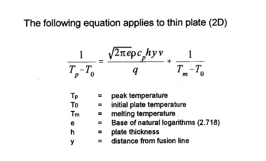
Calculation of heat-affected zone distance or width is not straightforward and very difficult. However, a simplified equation as provided in Fig. 3 below can be used for estimating HAZ distance/width for welding thin plates.
Fig. 3: Heat-Affected Zone Distance
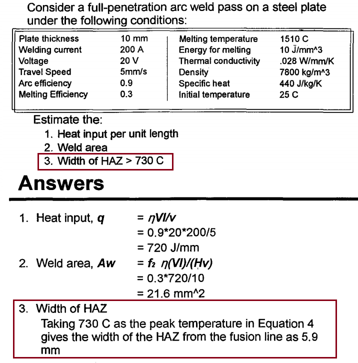
The above formula can be used to calculate the heat-affected zone distance. By knowing the peak temperature of the HAZ zone, the distance y can be calculated from the fusion line for welding a thin plate. Fig. 4 below provides a sample problem calculation regarding the same (Equation 4 mentioned in the answers is the equation shown in Fig. 3)
Fig. 4: Sample calculation of Heat Affected Zone Distance
Brittle Fracture and Ductile Fracture: Definition, Mechanism, Differences
A fracture can be defined as the separation of the material into two or more parts. Failure of material can involve any of the two mechanisms; ductile fracture or brittle fracture. Both these fracture mechanisms in metal are distinct and different from each other. In this article, we will explore both of these failure mechanisms in detail.
What is Brittle Fracture or Brittle Failure?
Brittle fracture is the sudden and rapid metal failure in which the material shows little or no plastic strain. This is characterized by quick failure without any warning. The generated cracks propagate rapidly and the material collapses all of a sudden.
Brittle Fracture is a condition that occurs when a material is subjected to temperatures that make it less resilient, and therefore more brittle. The potential for material to become brittle depends on the type of material that is subjected to these low temperatures. Some materials, such as carbon and low alloy steels will become brittle at low temperatures and therefore susceptible to damage ranging from cracking to shattering or disintegration of equipment.
When a material becomes brittle, the consequences can be very serious. If the brittle material is subjected to an impact or an equivalent shock (ex. rapid pressurization) the combination could potentially lead to a catastrophic failure under certain conditions.
What is Ductile Fracture or Ductile Failure?
Ductile fracture is the material failure that exhibits substantial plastic deformation prior to fracture. The ductile fracture process is slow and gives enough warnings before final separation. Normally, a large amount of plastic flow is concentrated near the fracture faces.
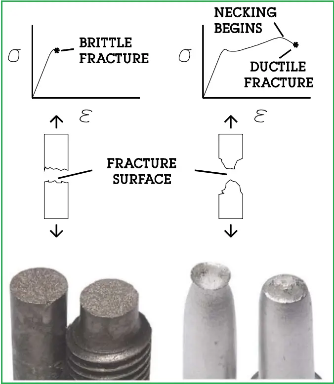
The ductile fracture occurs over a period of time and normally occurs after yield stress, whereas brittle fracture is fast and can occur at lower stress levels than a ductile fracture. That is why Ductile fracture is considered better than brittle fracture. Refer to Fig. 1 below that explains both fracture mechanisms. The area under the stress-strain curve represents the absorbed energy before failure. Clearly, the required energy in brittle failure is quite less than the ductile failure.
Fig. 1: Brittle vs Ductile Fracture
Brittle Fracture Mechanism
The mechanism of brittle fracture shown above is known as Brittle cleavage fracture. This occurs in metals with a high strain-hardening rate and relatively low cleavage strength.
Ductile materials under some conditions can become brittle if the conditions are changed. Such a condition is the effect of temperature. Many materials of industrial use exhibit ductile fracture at ambient and elevated temperatures and brittle fracture at low temperatures. The transition temperature below which a material is brittle and above which it is ductile is known as the Nil-Ductility Transition (NDT) temperature. This temperature is not constant but varies depending on prior mechanical and heat treatment and the nature and amounts of impurity elements. It is determined by the Izod or Charpy Impact tests. At temperature above the NDT temperature, some plastic deformation will occur before the fracture
With an increase in ductility, NDT decreases. So it is always preferred to increase ductility. The parameters that impact ductility are:
Grain Size: small grain sizes increase ductility and grain size is controlled by heat treatment.
Alloying Element: The addition of alloying elements can decrease grain size and thus decrease brittleness shifting the NDT to a lower temperature.
Cyclic stresses should be avoided for brittle materials. So, systems having thermal and pressure cycles should not be designed from brittle materials.
Causes of Brittle Fracture
The main concern with a brittle fracture or brittle failure is that under certain conditions failure occurs at stresses well below the yield strength. Such conditions are the presence of a flaw or crack. Brittle fractures are normally initiated by defects present in the manufactured product or fabricated structure or by defects that develop during service. These are basically stress concentrators and may take the form of.
Notches- discontinuities caused by abrupt changes in the direction of a free surface, often fracture initiators. Examples: sharp fillets, corners, holes, threads, splines, keyways, dents, gouges, or scratches.
Laps, folds, flakes, large inclusions, forging bursts, laminations, and undesirable grain.
Segregation, inclusions, undesirable microstructures, porosity, tears, cracks, or surface discontinuities are introduced during melting, deoxidation, grain refining, and casting operations.
Cracks resulting from machining, quenching, fatigue, hydrogen embrittlement, liquid metal embrittlement, or stress corrosion.
Brittle fracture normally occurs because of the propagation of such cracks at great speed. Smaller grain size, higher temperature, and lower stress tend to mitigate crack initiation. On the contrary, larger grain sizes, lower temperatures, and higher stress favor crack propagation. There is a stress level known as the lower fracture propagation stress below which a crack will not propagate at any temperature. With the increase in temperature, higher stress is required for a crack to propagate. A crack arrest curve defines the relationship between the temperature and the stress required for a crack to propagate.
Fracture Toughness
The amount of stress required to propagate a preexisting crack is indicated by the Fracture Toughness which depends on various factors mentioned below:
Metal composition
Metal temperature
The extent of deformations to the crystal structure
Metal grain size
Metal crystalline form
Flaw size
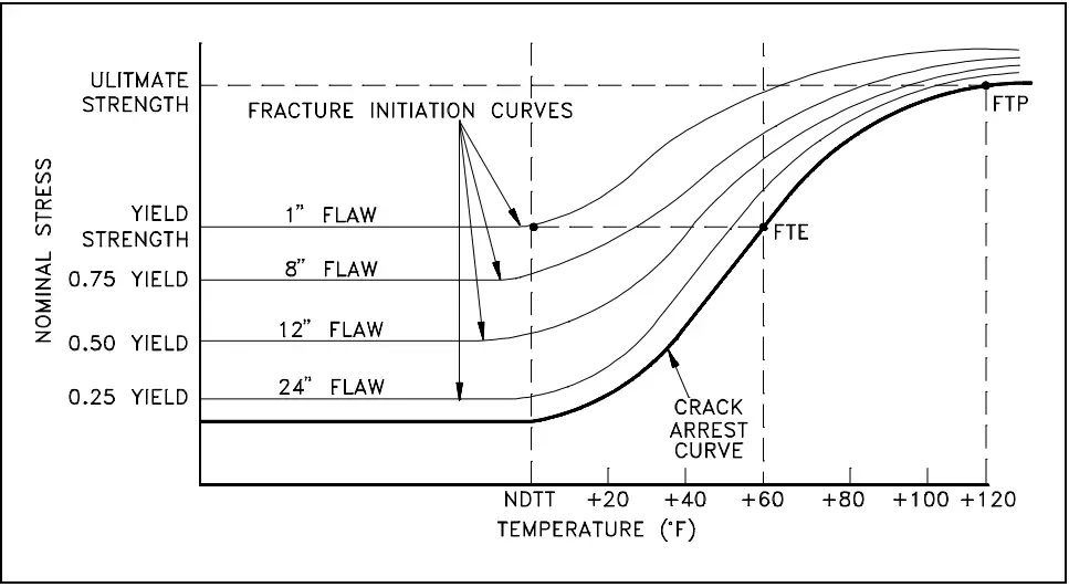
Refer to Fig. 2 below that represents fracture initiation curves for steel for various flaw sizes at various stresses and temperatures.
Fig. 2: Fracture Initiation Curve at various Flaw Sizes
From the above curve, it is evident that to avoid brittle fracture operating temperature should be maintained above NDT temperature. Maintaining the operating temperature above FTE temperature (NDT + 60°F for steel) will ensure greater safety.
Griffith’s Theory of Brittle Fracture
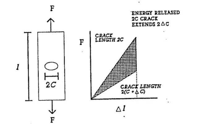
Consider a thin plate of length l having a thru-crack of length 2c, as shown in Fig 3. The upper curve shows the force-deflection curve for a non-extending crack of length 2c. For a non-extending crack of length 2(c + Δc), the curve will be the lower curve. The area between these two curves represents the energy released to extend the crack from 2c to 2(c + Δc).
Fig. 3: Explanation of Griffith’s Theory of Brittle Fracture
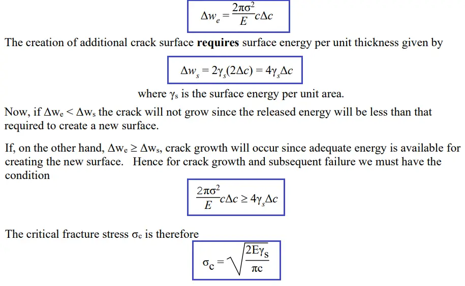
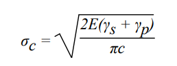
Using elasticity theory Griffith showed that the energy released per unit thickness during a crack growth of 2Δc is
Thus, the critical stress is inversely proportional to c½. Hence, the smaller the flaw, the greater the value of σc. The Griffith theory is good for every brittle material like glass, in which failure occurs without any plastic deformation. When there is some plastic deformation associated with the crack extension, we must add the plastic work γp expended in making the surface to the surface energy term γs to obtain σc as shown below:
The above equation forms the starting point of modern fracture mechanics.
Mechanism of Ductile Fracture
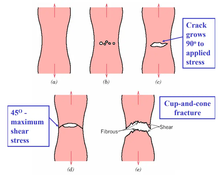
Ductile fracture or ductile failure (Fig. 4) normally occurs following the below-mentioned steps:
(a) Necking (b) Formation of microvoids (c) Coalescence of microvoids to form a crack (d) Crack propagation by shear deformation (e) Fracture
Fig. 4: Ductile Fracture Mechanism
Brittle Fracture vs Ductile Fracture
From the above discussions, it is clear that the brittle fracture and ductile fracture mechanism is completely different. The major differences between brittle and ductile fracture are provided below:
Brittle Fracture / Brittle Failure
Ductile Fracture / Ductile Failure
Negligible plastic deformation
Considerable plastic deformation.
Rapid and Quick Failure without any warning
Slow process with sufficient warnings
Quick Crack propagation
Slow crack propagation
Brittle fracture can occur below the yield strength
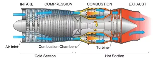
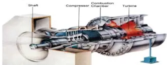
A gas turbine is a rotary machine in which the chemical energy of the fuel is converted into mechanical energy or kinetic energy in terms of shaft power. In other words, it is a mechanical power or thrust-delivering machine. It uses a gaseous working fluid for this purpose. The generated mechanical power can be used by industrial devices. There is a continuous flow of the working fluid in a gas turbine. Power generation gas turbines are the ones that produce shaft power. To propel an aircraft, gas turbines are used that convert fuel energy into kinetic energy for the generation of thrust. Fig. 1 below shows a typical representation of a Gas turbine.
Fig. 1: Representation of a gas turbine
Applications of a gas turbine
Major applications of gas turbines are found in:
As the direct and mechanical drive for various industries
Aviation
Electrical Power generation
Oil and gas industry
Marine propulsion
Turbo generators
Turbo-compressor
Automotive sector
Working principle of a gas turbine
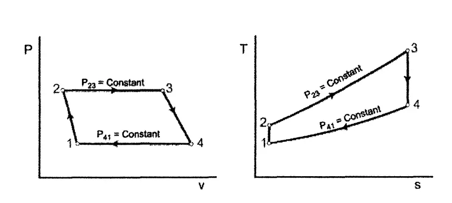
The working of a gas turbine is based on the thermodynamic Brayton Cycle. The Brayton cycle consists of two adiabatic work transfers and two constant pressure heat transfer heat processes (Fig 2). The gas undergoes an isentropic, adiabatic compression in State 1 to State 2. This process increases the temperature, pressure, and density of the gas. Next, heat is added at constant pressure in State 2 to State 3. For a gas turbine, a combustion process adds heat. During State 3 to State 4, the gas passes through an adiabatic isentropic turbine that decreases the temperature and pressure of the gas. In the case of a closed gas turbine Brayton cycle, heat is removed from the gas between State 4 and State 1 via a heat exchanger.
Fig. 2: Brayton Cycle
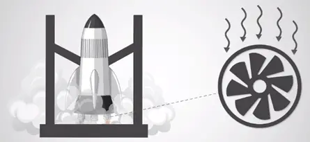
Let’s understand the basic operating principle of a gas turbine with the following example:
Imagine there is a rocket in which fuel is going to burn thereby creating high-pressure exhaust gas. According to energy conservation law, in high-pressure exhaust gas, the chemical energy of the fuel is converted into mechanical energy. The thrust of the exhaust gas tries to move the rocket forward when the rocket is fired. Now the question is if one fixes the rocket body with a mechanical structure in order to prevent its movement. What will happen?
In such a case, the high-pressure exhaust gas releases but in a backward direction. Now another case is that what if we add a set of turbine blades to this back-fired exhaust gas?
The released mechanical energy which is in the linear backward direction will transform into rotational movement of the turbine shaft which is a big success. This means the chemical energy of the fuel gas is transformed into rotational mechanical energy of the turbine shaft as shown in Fig. 3.
Fig. 3: Gas turbine working principle
In simple words, in a gas turbine, hot gases move through a multistage gas turbine. It has both stationary and moving blades just like a steam turbine. The stationary blades adjust their velocity and guide the moving gases to the rotor blades. The turbine’s shaft is coupled to a generator.
The working principle of a gas turbine in a power plant is as follows:
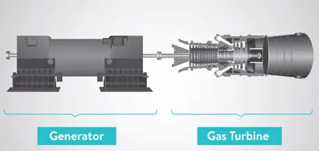
In a gas turbine power plant, there is a generator known as an electrical machine and this generator needs a prime mover which is a gas turbine in order to generate electricity as shown in Fig. 4.
Fig. 4: Gas turbine as a prime mover
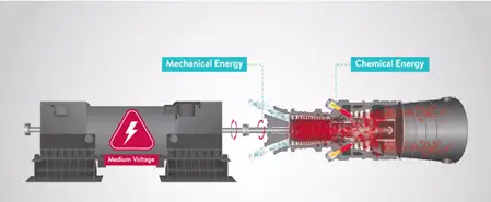
It transforms the fuel’s chemical energy into mechanical energy or in other words converting natural gas into mechanical energy. The generated mechanical energy is then transferred to the generator’s shaft through a gearbox. Now the turbine can create electrical energy as shown in Fig. 5.
Fig. 5: Mechanical energy to Chemical Energy in gas turbine system
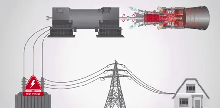
This prime form of electrical energy usually has a low or medium level of voltage. In order to manage power loss in transmission lines, step-up transformers are used to increase this voltage and the increased voltage is provided to the electrical energy which in turn is transmitted through the transmission lines and delivered to the grid as shown in the below Fig. 6.
A few points mentioned below should be kept in mind like:
For the oil and gas production process, the turbine is coupled to a compressor or a pump instead of coupling with a turbine.
An arrangement similar to a steam turbine is considered when one uses a gas turbine to drive a compressor.
The header tanks and lube oil are required in the auxiliary piping system.
The exhaust system should be considered which has ducting to a few heat recovery systems, that is, a process heater or a steam raising plant.
There should be a provision for the maintenance and operation of all machinery.
Outside the compressor house, combustion air must be taken to the turbine burner from a safe location. The most likely required items are an inlet silencer and filter.
Components of a gas turbine
Gas turbines have three main parts as mentioned below in Fig. 7:
Air compressor
Combustion chamber
Turbine
Fig. 7: Gas turbine components
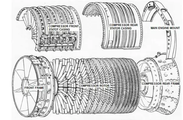
Air Compressor:
With the combustion chamber between the air compressor and turbine, both the air compressor and turbine are mounted on either end on a common shaft. Gas turbines require a starting motor as they are not self-starting. The use of an air compressor is to suck the air and compress it thereby increasing its pressure. Axial design type compressors (multi-stage) are preferred for the most advanced and large gas turbines.
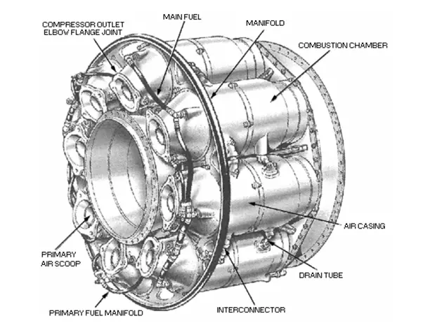
Here the compressed air is combined with fuel and the resulting fuel-air mixture is burnt and delivers the combustion products to the gas turbine. With the high pressure of air, the fuel mixture burns quite well. Nowadays liquid fuel, gaseous fuel, or natural gas is used in gas turbines. Generally, three types of combustion chambers are used:
annular combustor chambers
can (multi-can) combustor chambers
can-annular combustor chambers
Fuel is injected at the upstream end of the burner in the form of a highly atomized spray. Fuel nozzles may be a simplex type or dual fuel type. Some gas turbines are “bi-fuel” which means they have to ability to burn a mixture of gas and liquid fuel.
Fig. 9: Typical Combustion chamber of a gas turbine
Turbine:
There is a multistage gas turbine from where hot gases move and the kinetic energy is transformed into shaft horsepower. A gas turbine has both stationary and moving blades just like a steam turbine. The purpose of stationary blades is to guide the moving gases to the rotor blades and then adjust their velocity. The turbine’s shaft is coupled to a generator.
Exhaust Module:
The hot gases from a gas turbine exit through the exhaust section. The exhaust case consists of an inner and outer housing.
Other gas turbine parts are
Cooling system
Bearing and Lubrication system
Fuel system, etc
Types of gas turbine
The below listed are types of gas turbines:
Open-cycle gas turbine
Closed-cycle gas turbine
Aero derivative gas turbine
Scale jet engines
Auxiliary power unit
Jet engines
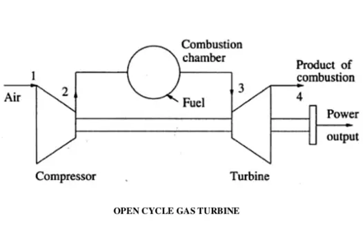
Open-cycle gas turbine
Open cycle gas turbine consists of three parts mainly a combustion chamber, turbine, and compressor. The compressor raises the pressure by taking in the ambient air. Fuel is burnt to add heat to the air in the combustion chamber thereby raising its temperature. The heated gases from the combustion chamber are then passed to the turbine where it does its mechanical work while expanding. The below figure (Fig. 10) shows an image of an open-cycle gas turbine.
Fig. 10: Schematic of an open-cycle gas turbine
Closed cycle gas turbine:
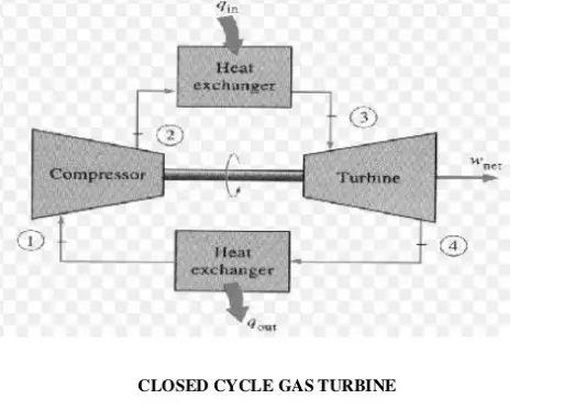
The working fluid used in a closed-cycle gas turbine is air or any other suitable medium that comes out from a compressor and is heated in a heater by some external source at a relatively constant pressure. The heated high-pressure and high-temperature air is then passed to the turbine. The fluid from the turbine is then cooled to its original temperature by some external cooling agent and then passed to the compressor. This way the working fluid is constantly used in the system and the required heat is given to the fluid by the heat exchanger without significant change in its phase. The below figure (Fig. 11) shows an image of a closed-cycle gas turbine.
Fig. 11: Schematic of a closed-cycle gas turbine
Aero derivatives gas turbine:
These types of gas turbines are used in electrical power generation because of their ability to handle load changes more quickly and the ability to shut down better than industrial machines.
These are also used in the marine industry in order to reduce weight.
Scale jet engines:
These are also known as miniature gas turbines.
The scale jet engines have the ability to produce up to 22 Newton’s of thrust and can be easily built by most of minded mechanical engineers with basic engineering tools such as a metal lathe.
Auxiliary gas turbine:
These are smaller types of gas turbines used to supply auxiliary power to aircraft. Auxiliary gas turbines are used to supply air conditioning and ventilation. They supply compressed air power to jet engines. They also supply mechanical power to the gearbox to start larger jet engines or to drive shafted accessories.
Design of a gas turbine
The factors that limit the size and efficiency of a gas turbine are the firing temperature, compression ratio, mass flow, and centrifugal stresses. The most critical areas in the gas turbine design that determines the engine efficiency and life are the hot gas path, i.e., the combustion chambers and the turbine first stage stationary nozzles, and rotating buckets. The components in these areas represent roughly 2% of the total cost of the gas turbine, but they control the gas turbine output and efficiency.
Nickel superalloys are normally used for gas turbine nozzles and buckets. These are coated under a vacuum with special metals (platinum-chromium-aluminide) to protect against the hot corrosion occurring at high temperatures in presence of contaminants like sodium, vanadium, and potassium.
The operating performance of gas turbines can be increased by the continuing improvements in firing temperatures and compression ratios. Air-cooled nozzles and buckets using bleed air from the compressor are major advancements to increase the firing temperature. This limits the metal temperatures of the nozzles and buckets to withstand hot corrosion and creep.
To provide additional turbine power output by increasing the Final compressor pressure, additional compressor stages can be added to the compressor rotor assembly to give a higher compression ratio.
Natural gas, diesel oil, residual or crude oil can be used as gas turbine fuel. With an increase in ambient temperature and altitude, the air density reduces. This causes a significant reduction in the power output and efficiency of the gas turbine. Ambient air temperature and elevation changes do not affect steam plants and diesel.
Codes and Standards
Frequently used codes and standards that govern the design, construction, testing, etc of a gas turbine are
API 616
ASME PTC 22
ISO 2314
ISO 3977
ISO 11086
ISO 7919
ISO 10494
ISO 11042
ISO 21789
ASME 133
NFPA 37
IEC 60034
ISO 19859
Gas turbine performance
The factors that impact the performance of a gas turbine are
Inlet air density
Ambient air temperature
Altitude and ambient pressure
Humidity
Inlet and exhaust pressure losses
Number of shafts
Advantages of a gas turbine
Fuel storage requires less area and handling is easy.
The maintenance cost is less.
Construction is quite simple.
Compared to steam power plants, it does not require a condenser, boiler, or other accessories.
Fuels such as kerosene, benzene, paraffin, and powdered coal can be used which are cheaper than other petrol and diesel.
In the areas of water scarcity, gas turbines can be used.
It creates less pollution.
It requires less amount of water.
Disadvantages of a gas turbine
Most of the developed power is used to drive the compressor.
This is the reason that a gas turbine has low thermal efficiency.
High-frequency noise comes from the compressor which is again questionable.
For various parts of the turbine, special metals and alloys are used because the running speed of the turbine is 40000 to 100000 rpm and the operating temperature is 1100 to 1260 degrees Celsius.
Gas turbine manufacturers
The major share of gas turbine manufacturing is controlled by the following organizations:
General Electric (US)
Siemens (Germany)
Mitsubishi Hitachi Power Systems (Japan)
Ansaldo STS (Italy)
Solar Turbines (U.S.)
Kawasaki Heavy Industries, Ltd (Japan)
Doosan Heavy Industries & Construction (South Korea)
Bharat Heavy Electrical Limited (India)
OPRA Turbines (The Netherlands)
Vericor Power Systems LLC (U.S.)
Rolls-Royce (U.K)
The first three companies in the above list combinedly control more than 80% of the gas turbine market share.
Gas turbine vs steam turbine
The main differences between a gas turbine and a steam turbine are listed in the following table:
The pour point of a liquid (crude oil or a petroleum fraction) is the temperature below which the liquid becomes plastic and loses its flow characteristics. So pour point is the demarcation point of a fluid’s flowability and an important parameter of liquids at low temperatures. Above the pour point temperature, the liquid will flow without stirring, under standard conditions. This is the lowest temperature at which the oil will flow under gravity. The pour point of a liquid depends on its molecular structure and the presence of waxes in the liquid.
Significance and Features of Pour Point
The pour point indicates a liquid’s lower temperature properties.
If the surrounding temperature is less than the pour point, it cannot be transferred through a pipeline.
The pour point is more significant for Lubricating oils.
Pour points provide the lowest temperature for that fluid at which it can transfer by pouring.
The high value of the pour point means it can become semi-solid at that temperature which may cause jamming of the machine during operation.
For Lubricating oils, the pour points determine the liquid’s suitability be used as a lubricant at sub-zero temperatures. Also, the pour point indicates the dissolved wax concentration in the oil.
The pour point is used to allow process dimensioning and pumping calculations and in preventive actions and process improvement.
Pour Point Measurement
There are two methods for measuring the pour point of a liquid; the Manual method and the Automatic method.
Manual Method of Pour Point Measurement:
ASTM D97 (ISO 3016 or IP 15) standard provides the standard test methods for determining the pour point of Crude oil. As per these standards, the Crude oil specimen is cooled inside a cooling bath. Paraffin wax crystals are formed upon cooling. At about 9°C above the expected pour point, and for every subsequent 3°C, the test jar is removed from the cooling bath and tilted to check if the crude oil surface is moving. When the crude oil specimen ceases to flow when tilted, the jar is held horizontally for 5 sec. If the liquid does not flow, the pour point of crude oil is determined by adding 3°C to the result. So Pour Point=Temperature at which the liquid does not flow+3°C.
Pour Point Measurement
Automatic Method of Pour Point Measurement:
ASTM D5949 provides the automatic method for pour point measurement of petroleum products. This method is known as the Automatic Pressure Pulsing Method. Under ASTM D5949, the test sample is heated and then cooled by a Peltier device at a rate of 1.5±0.1 °C/min. A pressurized pulse of compressed gas is imparted onto the surface of the sample at either 1 °C or 3 °C intervals. The liquid sample is continuously monitored for movement by multiple optical detectors. The lowest temperature at which surface movement is detected on the sample is indicated to be the pour point. The pour point of crude oils generally relates to their paraffin content. With an increase in the paraffin content, the pour point of crude oil increases.
Typical Pour Point Values
The pour point for Crude oils ranges from 32 °C to below −57 °C (90 °F to below −70 °F). Some typical values of the Pour Point are provided below in the table:
Liquid
Pour Point
Multi-grade engine oil
-35 Deg. C
Monograde engine oil
-23 Deg. C
Turbine Oil
-18 Deg. C
Synthetic Polyol ester
-32 Deg. C
Castor Oil
-33 Deg. C
Coconut Oil
21 Deg. C
Groundnut Oil
3 Deg. C
Mustard Oil
-18 Deg. C
Sunflower Oil
-18 Deg. C
Olive Oil
-9 Deg. C
Kerosene
-69 Deg. C
Table: Typical Pour Point Values for Oils
Factors Affecting Pour Point of Crude Oil
Factors that directly affect the pour point of crude oil are
Temperature differential
Paraffin wax content
Flow rate
Surface Properties
Viscosity
Due to the presence of high content of high molecular weight components, such as waxes, asphaltenes, and resins, Heavy and extra-heavy crude oils normally have higher pour points. The pour point of a liquid can be improved using depressants like polymethacrylates, alkylated wax phenol, Alkylated wax naphthalene, etc. Such depressants modify the interface between the oil and wax present.
A Steam Turbine is an engine that converts heat energy from pressurized steam into mechanical energy where the steam is expanded in the turbine in multiple stages to generate the required work. Steam turbine engines are used to produce electricity and drive countless machines worldwide (used as the prime mover for pumps, compressors, and other shaft-driven equipment). The capacity of steam turbines can vary from a few kilowatts to several hundred megawatts. Sir Charles A. Parsons developed the first modern steam turbine in 1884.
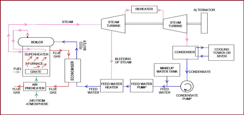
The Power in a steam turbine is generated by the rate of change of momentum of a high-velocity jet of steam impinging on a curved blade that is free to rotate. Fig. 1 below shows a schematic representation of a steam turbine with its associated auxiliaries.
Fig. 1: Schematic of Steam Turbine Power Generation
Working Principle of Steam Turbines
The heat energy of steam is converted into mechanical work while expanding in the turbine. Steam is generated inside a boiler. The expansion of steam takes place through a series of fixed blades (nozzles) and moving blades. The working of a steam turbine is based on the thermodynamic cycle called the “Rankine cycle”.
Rankine Cycle:
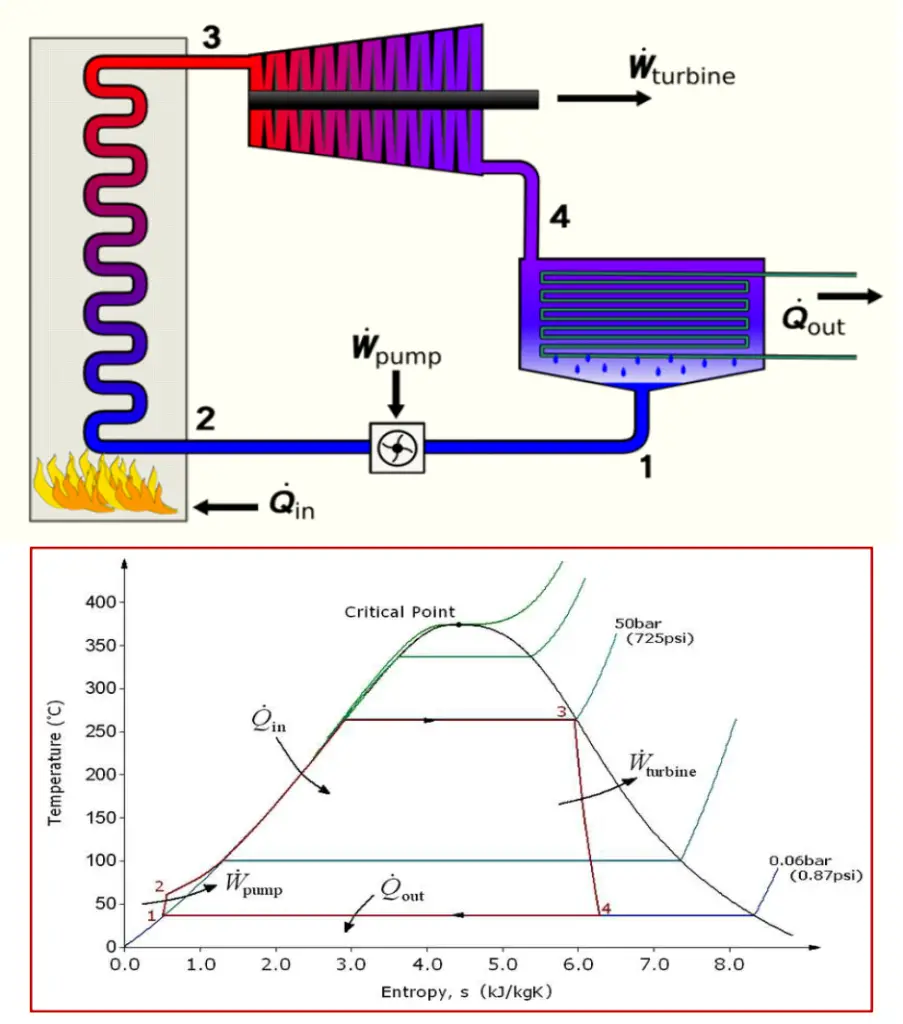
The Rankine cycle is an idealized thermodynamic cycle of a heat engine that converts heat into mechanical work while undergoing a phase change. The concept is developed by William John Macquorn Rankine, a Scottish polymath and Glasgow University professor. It is an idealized cycle in which friction losses in each of the four components are neglected. The heat from an external source is supplied to a closed-loop, which normally uses water as the working fluid. Refer to Fig. 2
Fig. 2: Rankine Cycle
Fig. 2 above represents the Rankine Cycle and the Temperature and Entropy are plotted in the curve. The processes can be described as follows:
Process 1–2 Isentropic compression – Adiabatic Pumping: The working fluid is pumped from low to high pressure. The fluid, being liquid at this stage, the pump requires little input energy.
Process 2–3 Constant pressure heat addition in a boiler – Isobaric Heat Supply: The high-pressure liquid enters a boiler, where it is heated at constant pressure by an external heat source to become a dry saturated vapor (steam). The required energy input can easily be calculated graphically, using an enthalpy–entropy chart (Mollier diagram or h-s chart), or numerically, using steam tables.
Process 3–4 Isentropic expansion – Adiabatic Expansion: The dry saturated vapor expands through a turbine, generating power. The temperature and pressure of the vapor are reduced causing some condensation.
Process 4–1 Constant pressure heat rejection in condenser – Isobaric Heat Rejection: The wet vapor then enters a condenser, where it is condensed at a constant pressure to become a saturated liquid.
Types of Steam Turbines
Steam Turbine Types can be classified based on various parameters as listed below:
According to the action of steam
Impulse Turbine and
Reaction Turbine
According to the number of pressure stages or impellers
Single-stage Turbine and
Multistage Turbine
According to the type of blade row
Rateau type(Pressure compounded stages)
Curtis type (Velocity compounded stage)
Reaction stage type
According to the type of steam flow
Axial flow turbine and
Radial flow turbine
According to the number of shafts
Single-Shaft
Multi-shaft.
According to the direction of Shaft
Transverse type
Vertical type
According to the method of governing
Throttling
Nozzles
Bypass governing.
According to the heat drop process:
generators
one or more intermediate-stage extraction
back pressure
topping.
According to steam conditions
Low-Pressure Steam Turbine
Medium Pressure Steam Turbine
High-Pressure Steam Turbine
Very High-Pressure Steam Turbine
Supercritical Pressure Steam turbine
According to Exhaust conditions
Condensing Turbine
Backpressure Turbine
Extraction Turbine
According to the Exhaust flow
Single-flow exhaust type
Multi-flow Exhaust type
According to Exhaust Direction
Down exhaust
Top exhaust
Axial exhaust
According to speed
Fixed speed
Variable speed
Low Speed (≤ 3000 rpm)
High Speed(≥ 3000 rpm)
According to the quantity of the inlet valves
Single valve type
Multi-valve type
According to the existence of reducer
Direct-drive type
Reduction type
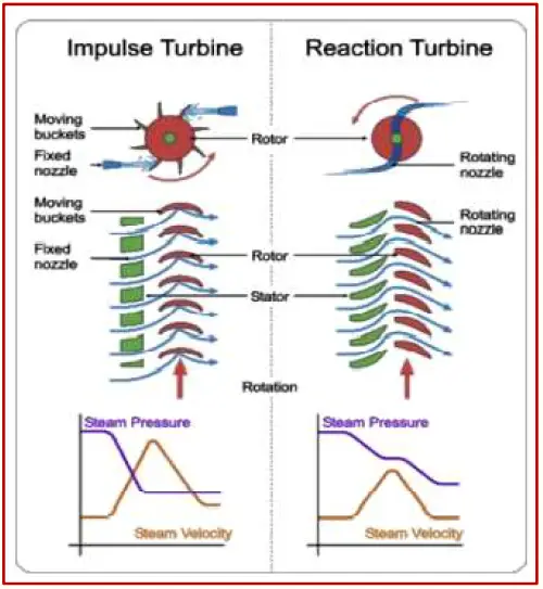
The most basic steam turbine types are Impulse Turbine and Reaction turbine.
Impulse Steam Turbine
The basic idea of an impulse steam turbine is that a jet of steam from a fixed nozzle pushes against the rotor blades and impels them forward. So the impulse force of high-velocity steam exerts a force on the blade to turn the rotor. The kinetic energy of the steam is transferred to the rotating wheel by momentum transfer within the blades. Pelton Wheel, Banki Turbine, etc are typical examples of Impulse turbines.
Reaction Steam Turbine
In the reaction steam turbine, a jet of steam flows from a nozzle on the rotor (the moving blades) by fixed blades designed to expand the steam. The rotor gets its rotational force from the steam as it leaves the blades. Roughly 50% of the output power is generated by the impact force and the other 50% from the reaction force by the steam expansion. Francis Turbine, Kaplan Propeller turbine, Deriaz turbine, etc are examples of reaction turbines.
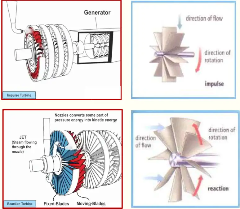
The main difference between impulse and reaction turbines lies in the way in which steam is expanded while it moves through them such that:
In the impulse-type steam turbine, the steam expands in the nozzle and its pressure doesn’t change as it moves over the blades.
In the reaction type, the steam expands continuously as it passes over the blades and thus there is a gradual fall in pressure during expansion.
Fig. 3: Impulse Turbine vs Reaction Turbine
The major differences between an impulse turbine and a reaction turbine are tabulated below:
Impulse Steam Turbine
Reaction Steam Turbine
In an impulse turbine, The steam flows through the nozzle first and then strikes the moving blade.
In a reaction turbine, Steam flows through the guide mechanism first and then through the moving blades.
Blades rotate only by impact force
Blades rotate by impact force and reaction force generated by steam expansion.
Relative fluid velocity remains constant across the blades
The relative fluid velocity increases across the blade.
The number of stages is less for impulse steam turbines for the same heat input.
Reaction steam turbine has more stages under the same heat supply.
More efficiency
Comparatively less efficient
Less Maintenance requirement
More Maintenance requirements.
The casing does not perform any hydraulic function but is required to prevent fluid splashing.
The casing is a must to contain the pressure.
Fluid Flow is tangential to the turbine wheel
Fluid flow is radial or axial to the turbine wheel.
Suitable for small power generation.
Ideal for higher power generation requirements.
High operating speed
Low Operating Speed.
Impulse Turbine vs Reaction Turbine
Fig. 4: Difference Between Impulse and Reaction Turbine
Selection of Steam Turbines
The following table from JIS B0127 provides typical guidelines for the general features and selection criteria based on the type of steam turbines. Depending on the purpose, use, required output, location, arrangement, and circumstances appropriate type of steam turbine should be selected:
Type of Steam Turbine
General Features
Selection Criteria
Use for
Condensing Steam Turbine
The turbines which work fully inflated to low pressure by obtaining a high vacuum in order to condense turbine exhaust steam in the condenser.
(1)When only electricity or power is required, (2) When cooling water to condensate exhaust steam is available.
Machine drive, geothermal power, heat recovery
Regenerative Steam Turbine
The condensing turbine which is obtained high efficiency of the turbine cycle by utilizing extracted steam from the middle stage for heating boiler feed-water by the feed-water heater.
(1)When small and middle output and high efficiency are required, (2) When cooling water to condensate exhaust steam is available.
Power generation for cement, ironworks, mine
Reheat Steam turbine
The turbines extract steam from the middle expansion stage, re-heat, back to the turbine and expand further.
(1)When large output and high efficiency are required, (2)In general, it is used as a regenerate and reheat turbine.
Large-scale power generation
Back-pressure Steam Turbine
The turbine’s exhaust pressure is above atmospheric pressure and utilizes steam as utility steam. In some cases, it may be operated exhaust released into the atmosphere.
(1)When a large amount of utility steam of a type is required, (2)It is necessary to operate electricity and steam in parallel due to excess and deficiency between generated electricity and the power demand of the plant.
Private power generation, machine drive, cogeneration
Extraction Condensing Steam Turbine
The turbines extract steam from the middle stage of condensing turbine after adjusting pressure by the control valve and utilize steam and exhaust steam as utility steam for works and others.
(1)When a large amount of utility steam of one or more types is required, (2)When the power demand is less than the amount of utility steam.
Private power generation, machine drive, cogeneration
Extraction back pressure Steam turbine
The turbines extract steam from the middle stage of the back pressure turbine after adjusting pressure by the control valve and utilize steam and exhaust steam as utility steam for works and others.
(1)When a large amount of utility steam of more than two types is required, (2)It is necessary to operate electricity and steam in parallel due to excess and deficiency between generated electricity and the power demand of the plant.
Private power generation, machine drive
Mixed-pressure Steam Turbine
The turbines which are made work into same turbine different pressure steam.
(1)When only electricity or driving power is required. (2)When it is necessary to collect low-pressure steam. (3)When it is capable to get cooling water for condensation of exhaust steam.
Private power generation by heat recovery, machine drive
Selection Criteria for Steam turbines
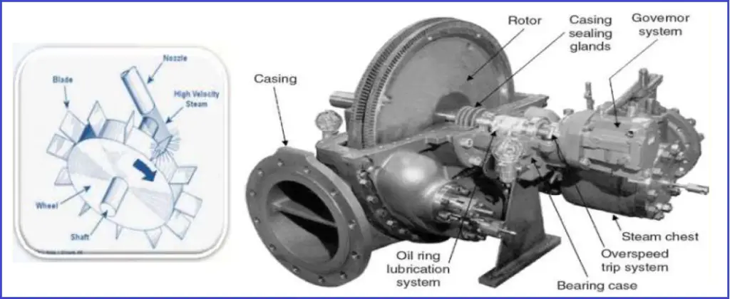
Components of a Steam Turbine
The major components that constitute a steam turbine are:
Casing: The Casing should withstand all normal and emergency service loads and allowable piping forces and moments caused by temperature change. The design of turbine casing design shall be such that thermal stresses are minimized. Adequate support must be provided to the steam turbine casing to maintain good alignment with the rotor.
Nozzles.
Rotor: This is the main component in a steam turbine that carries the blades to convert thermal energy.
Blades: Blades absorb the energy of high steam velocity and convey it to the rotor. The shape of the blades significantly affects the turbine performance of turbine and requires high reliability.
Governor for speed control.
Servo Mechanism.
Oil Pump for lubrication.
Fig. 5 shows these components.
Fig. 5: Steam Turbine Components
Construction of a Steam Turbine
Often, Turbines are described by the number of stages that are grouped into different sections of the turbine. Depending on the pressure levels, the sections are known as the high pressure (HP) section, intermediate pressure (IP) section, or low pressure (LP) section. These turbine sections can be constructed in different types as mentioned below:
can be packaged into separate sections in a single turbine casing,
can be arranged into separate casings for each section, or
can be constructed in combination (HP/IP turbines in one casing and LP turbines in another).
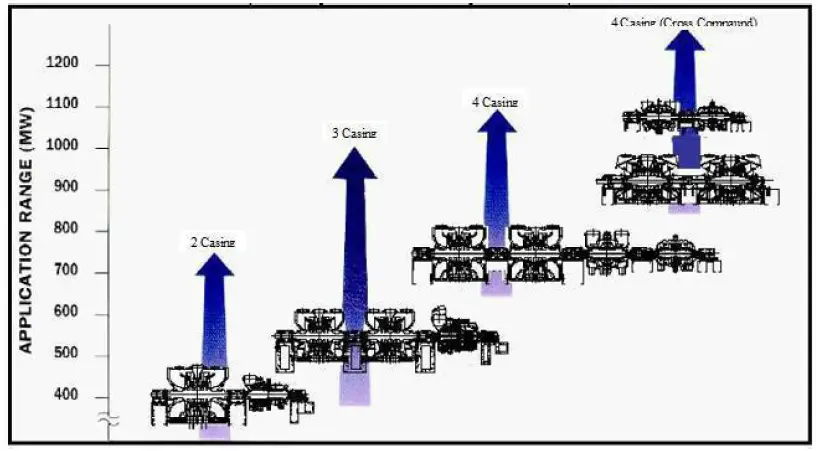
Also, two turbines may be connected together in the same casing but in opposing directions to balance the thrust loads. Flow to these turbines is through the center of the casing and exits from each end of the turbine. These are referred to as turbines with double flows (i.e., opposing flow paths on the same shaft). However, the steam turbine MW rating is not indicative of section or casing numbers. Normally, less number of stages and casing will result in larger size blading and high loading for the same steam condition. The following Fig. shows a typical plot of the number of turbine casings as a function of steam turbine size
Fig. 6: Number of Turbine Casing vs Steam Turbine Size
Various techniques are employed to maximize steam turbine efficiency, each designed to attack a specific loss mechanism. For example:
the number of stages utilized can range from the fewest possible to develop the load reliably to the thermodynamically optimum selection.
Spill bands can be utilized to minimize throttling losses.
High-efficiency nozzle/bucket profiles are available to reduce friction losses.
To reduce the pressure within the exhaust casing, exhaust flow guides are available.
The specific features employed on a given application are usually based on the trade-off between capital investment and the cost to produce steam over the life of the turbine –SIMPLY, IT IS AN OPTIMIZATION APPROACH.
Process Surveillance – Why we should monitor closely?
Accurate measurement and tracking of parameters like temperature, pressure, and flow are important to plant safety and performance. Information collected at specific measuring points can be used to:
Avoid Metallurgical Failures: Temperatures need to be maintained below components’ melting points in order to avoid metallurgical failure. Too-high temperatures can also lead to creep deformation in the rotating blades.
Determine Efficiency and Performance: Calculate the efficiency of the turbine by knowing the inlet and exit temperatures, as well as the flow rate at the nozzle. When a turbine exhaust is used as heat input to a steam cycle, engineers can also estimate the performance of the heat recovery steam generator (HRSG) by using the temperature and flow measurement of the turbine exhaust.
Detect Inefficiencies: High exhaust temperatures and flow changes can be symptoms of an upset mode of turbine operation. If a flow measurement device picks up irregularities, the plant operator can perform a diagnostic to identify the underlying causes.
Calculate Residual Life: Tracking temperatures over time allows one To calculate how much life the component has left and to plan maintenance and replacements.
Process Surveillance – What & Where?
Barometric pressure.
Steam and steam condensate’s flow rate, temperature, and pressure on:
The cold reheat.
The high-pressure throttle.
The hot reheat.
Low-pressure induction sections.
Exhaust pressure.
Steam Turbine Codes and Standards
API 611 (ISO 10436) 4th Edition – General purpose steam turbines for refinery service (non-critical):
General purpose turbines are horizontal or vertical turbines used to drive equipment that is usually spared, is relatively small in size (power), or is in non-critical service.
They are used where steam conditions will not exceed a pressure of 48 bar and a temperature of 400°C or where speed will not exceed 6000 rpm.
API 612 (ISO 10437) 6th Edition – Special purpose steam turbine for refinery service (critical):
The purchaser’s approval is required for built-up rotors when blade tip velocities exceed 250 m/s at maximum continuous speed or when stage inlet steam temperatures exceed 440 °C.
Over Speed shutdown system:
I. Electronic Overspeed detection system.
II. Electro-hydraulic solenoid valves.
III. Emergency trip valve(s) / combined trip and throttle valve(s).
If specified a turbine with an exhaust pressure less than atmospheric pressure shall be provided with an exhaust vacuum breaker actuated by the shutdown system.
Details of such a system shall be agreed upon by the purchaser and the turbine vendor.
Other codes and standards that are referred to for steam turbine applications are
ASME/NEMA SM23
NEMA SM24
IEC 60045
IEEE 122
IEC 60953
IEC 60962
IEC/TS 61370
BS EN60045-1
ASME PTC 6/6A
ASME/ANSI PTC 20.1/20.2
ISO 14661
IS 14205
JESC T0003
JEAC 3703
JIS B8101
DIN 4304
DIN 4305
DIN 4312
DIN EN 45510-5-1
Steam Turbine Manufacturer
Steam turbines are highly complex and sensitive pieces of machinery, and only a few manufacturers produce them worldwide. The majority of the steam turbines are manufactured by the following companies:
Harbin Electric
Shanghai Electric
Dongfang Electric
General Electric
Siemens
Alstom
Bharat Heavy Electricals Limited
Doosan
Mitsubishi Heavy Industries
Weir Allen
Elliot Group
and Toshiba.
Online Steam Turbine Courses
To update yourself regarding more details of steam turbines, the following online courses will help you. To enroll in any course, click on the subject, review the course and then enroll.
In the world of engineering, manufacturing, and facility management, maintenance plays a crucial role in ensuring the longevity and efficiency of equipment and systems. From machinery in a manufacturing plant to oil and gas systems or HVAC systems in a commercial building, effective maintenance strategies are essential for minimizing downtime, reducing costs, and enhancing safety.
What is Maintenance?
Maintenance is the effort required to undertake for maintaining equipment performance similar to new ones. Unscheduled downtime due to equipment malfunction is one of the major concerns for industries, which calls for billions of dollars of losses each year. Maintenance is an important aspect of increasing productivity by reducing such downtimes and improving equipment performance. Maintenance is basically a set of processes and practices that help in the continuous and efficient operation of assets. The major benefits of maintenance are
Increase in the life of the equipment and other assets.
Optimization of asset performance.
Reducing unwanted downtimes, thus increasing production
Minimizing cost
Types of Maintenance
Broadly, there are two main types of maintenance categories that can further be subdivided into various maintenance-type groups.
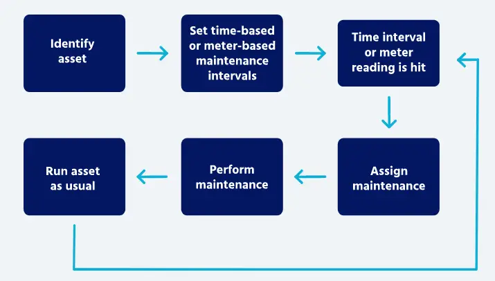
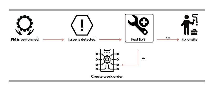
Preventive maintenance refers to the fixing of problems before they appear. This means such maintenance prevents the problem. Inspection of equipment at regular intervals to check the machine’s condition and take necessary action is the motto of preventive maintenance.
It involves scheduled inspections, adjustments, and minor repairs designed to prevent equipment failures before they occur. This strategy is proactive, focusing on keeping assets in good working condition. Fig. 1 below shows a typical workflow of the preventive maintenance philosophy.
Fig. 1: Work-flow of Preventive Maintenance
Preventive maintenance is categorized into the following five types
Time-based maintenance or TBM calls for maintenance at a fixed time. Normally, taking guidance from the equipment manufacturer’s maintenance plan a fixed interval is scheduled and maintenance work is performed to restore equipment efficiency and performance. Time-based maintenance also requires the replacement of items based on their service life capability.
Predictive Maintenance (PDM)
As the name suggests, this type of maintenance refers to the prediction of the failure probability of equipment and scheduling maintenance to prevent failure. To correctly predict the equipment’s workability and perform predictive maintenance the organization should keep and analyze the following data:
Equipment history
All records of downtime, defects, performance, etc
Equipment condition with respect to working time.
After analysis of the above data and including the experience with similar equipment maintenance dates are fixed.
Failure Finding Maintenance
In failure finding maintenance, potential hidden failures are searched at regular intervals and if discovered are repaired to prevent major breakdowns. So basically this is not a specific type of maintenance but a functional check. Failure to find maintenance increases the system’s reliability.
Condition-Based Maintenance
In the Condition-based maintenance (CBM) strategy, the actual asset condition is monitored and further maintenance requirement is decided. In this type of maintenance, based on visual inspection, scheduled tests, performance data, etc the equipment condition is studied. When some sign of decreasing performance or failure is received, maintenance is scheduled.
Risk-Based Maintenance
Risk-based maintenance considers the philosophy of maintaining the assets carrying the most risk during failure. This philosophy determines the most economical use of the maintenance resources and optimizes the risk of failure. Risk-based maintenance strategy works on the following steps:
Data Collection
Risk Assessment and Evaluation of Consequence and Probability of failure
Ranking of Risks
Creating an Inspection Plan based on those risk ranking matrices.
Maintenance planning and Mitigation of risks.
Equipment carrying the greater risk and failure consequences is frequently monitored and maintained. This philosophy and method provide a systematic approach to determining the most appropriate asset maintenance plans in the most economic way.
Advantages and Disadvantages of Preventive Maintenance
Advantages
Reduced Downtime: Regular maintenance helps identify potential issues before they lead to breakdowns.
Increased Equipment Lifespan: Regular care can extend the life of machinery and equipment.
Cost Savings: Preventive measures can save money by reducing the need for major repairs.
Disadvantages
Time and Resource Intensive: Requires scheduling and can lead to temporary downtime during inspections.
Over-Maintenance Risk: Performing maintenance too frequently can waste resources if equipment is still in good condition.
Corrective maintenance is any maintenance task that resolves a problem with a piece of equipment and returns it to operational condition. This is also known as reactive maintenance. Corrective maintenance work can be both planned and unplanned. The following image shows the workflow of typical corrective maintenance philosophy.
Fig. 2: Work-flow of Corrective Maintenance
Normally there are three situations that call for corrective maintenance:
If a piece of equipment or part breaks down
If any issue is identified during condition monitoring
If routine inspection discovers any potential fault.
Reactive maintenance, often referred to as “breakdown” or “emergency” maintenance, occurs after equipment has failed or broken down. This type of maintenance is unplanned and is typically initiated in response to a malfunction.
There are two types of corrective maintenance
Planned or Scheduled corrective maintenance and
Unplanned or Unscheduled corrective maintenance
Planned or Scheduled Corrective Maintenance
Planned corrective maintenance is the corrective action that is not immediate but planned or scheduled depending on the urgency and nature of the deficiency identified. The risks involved and costs involved are major parameters to determine the planned corrective maintenance schedule. This is also known as deferred corrective maintenance. Example: An AC is not providing proper cooling due to refrigerant gas leakage. So, s work order is created to repair it during the next inspection.
Unplanned or Unscheduled corrective maintenance
Unplanned corrective maintenance needs immediate attention due to some kind of critical failure and must be repaired without delay as it directly relates to cost. This philosophy is also known as Immediate Corrective Maintenance. Example: A pump is inspected and repaired after every 200 hours but it breaks down after 150 hours of operation and it calls for an emergency repair. Similar cases are examples of unplanned corrective maintenance.
Advantages and Disadvantages of Corrective Maintenance
Major advantages of Corrective Maintenance are:
Minimal planning requirement
Lower short-term costs
Simplified maintenance process
For non-critical equipment, without much impact, this is the best maintenance philosophy and can be cheaper.
The main disadvantages of Corrective Maintenance are:
Increased Unpredictability
Paused operations and hence production loss
The increased cost of maintenance
Equipment life is not optimized.
Higher long-term costs
High safety concerns
Preventive Maintenance vs Corrective Maintenance
Let’s have a look at the major differences between Preventive and Corrective maintenance. For ease of understanding and comparing the differences between corrective and preventive maintenance are tabulated below:
Corrective Maintenance
Preventive Maintenance
Corrective maintenance refers to maintenance after the failure of an asset.
Preventive maintenance is aimed at preventing failure and is scheduled before equipment failure.
Corrective Maintenance is a less complex and simple process.
Preventive Maintenance involves proper planning to prevent equipment failure, Hence it is complex.
Corrective maintenance is normally more expensive as equipment has already failed and needs replacement or extensive repairs.
It prevents equipment failure and thus preventive maintenance is normally less expensive.
Loss of production and time due to asset failure
The chances of equipment failure are reduced to negligible production and time loss.
It is only performed when a breakdown occurs.
Preventive Maintenance is performed at regular intervals.
Corrective Maintenance increases the need for preventive actions.
Preventive Maintenance reduces the need for corrective actions.
Overall equipment lifecycle and efficiency reduces
Equipment lifespan and efficiency are increased by regular preventive maintenance
This is hazardous considering the safety
From the safety of employees and working environment considerations, preventive maintenance is better.
It requires a greater number of employees or technicians to perform corrective maintenance which increases the workload.
The smaller number of technicians perform preventive maintenance decreasing the workload.
Table-1: Corrective vs Preventive Maintenance
Online Courses on Maintenance Aspects
To learn more about various maintenance aspects, Enroll in the below-mentioned courses, by clicking on the subject: