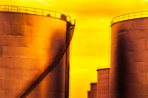
Storage tanks play a vital role in various industries, including oil and gas, chemicals, food and beverage, and water treatment. They are used for storing liquids, gases, and even solids. Understanding the construction of storage tanks is essential for professionals in these fields, as well as for those interested in engineering and infrastructure development.
The method statement for storage tank construction provides detailed information on the procedure and rules for conducting all fabrication, erection, and testing of the storage tanks and similar static equipment. All the tasks/activities should be completed with the utmost care, with good workmanship, and in accordance with the specifications to realize satisfactory completion of the entire activities. This document will provide a reference for a proper methodology to realize the activities during a proper sequence for fabrication, erection, and testing of the storage tanks.
What is Storage Tank Construction?
Storage tank construction refers to the process of fabricating and installing tanks used for storing liquids, gases, or solids. This involves various stages, including site preparation, foundation work, tank fabrication (either on-site or off-site), installation of piping and accessories, and adherence to safety and regulatory standards. The construction can involve different materials, such as steel, concrete, or fiberglass, depending on the intended use and environmental conditions. Proper design and construction ensure the tanks’ structural integrity, safety, and efficiency in storage operations.
Reference Codes and Specifications for storage tank construction
The required codes and specifications for the storage tank construction are
- API 650
- IS 803
- ASME Sec IX
- Approved Drawing / Specification
- ASME Sec V
Storage Tank Construction Methodology
The storage tank construction methodology can be performed in the sequence listed below:
- Identification of Tank Materials
- Tank Construction and Fabrication
- Annular and Bottom Plate Fabrication
- Shell Plate Fabrication
- Roof Plate Fabrication
- Appurtenances
- Spiral Stairway and handrailing
- Storage Tank Erection
- Annular Plate laying
- Bottom Plate laying
- Erection of Cone Roof plates and Structures
- Shell Course Erection
- Appurtenances installation
1. Identification of Tank Materials
All items required for tank fabrication, like plates, fittings, and other components of the tankage system, must be clearly identified by marking heat numbers by hard-punching on each part. Each weld joint shall be marked with a joint number and a welder number.
2. Storage Tank Construction and Fabrication
All fabrication works like tank material identification, marking, cutting, rolling and welding must be performed as mentioned in the latest API 650. The workmanship shall be good in every respect. It must be meeting all safety, Quality Control & Non-Destructive Testing requirements, with the coordination of the Engineer-In-Charge.
- Lay all the plates, Structural & pipes in such a fashion that facilitates proper checking of dimensions & heat no.
- Mark the components as per the drawings.
2.1 Tank Annular and Bottom Plate Fabrication
- Mark the plates as per the drawing
- Perform the cutting operation after proper inspection.
- All the cutting operations shall be administered by Gas Cutting.
- Grind the cut edges smoothly to get rid of burrs and slag.
- Stack the plates at designated places within the fabrication yard in proper Sequence.
- The backing strip shall be fitted and tacked with an annular plate as per the drawing.
- After completion of the fabrication, the underside of the annular and bottom plates shall be blast cleaned and painted as per the specification to the satisfaction of the engineer-in-charge.
- Check the joint position and root gap for welding after welding inspection by weld visual & NDT as per API 650.
2.2 Tank Shell Plate Fabrication
- Lay all the plates within the open area such as how easy it is for marking and cutting.
- Mark the plates as per the drawing and to the satisfaction of the engineer in charge.
- The cutting operation including beveling shall be administered by the gas-cutting method on all four sides.
- Grind the cut edges smoothly to get rid of slag and burr.
- The stings-prepared plates shall be shifted by crane to the rolling area.
- The plates shall be fed to the rolling machine. by means of a crane & proper lifting tools and tackles.
- The plate shall be rolled as per drawing details and therefore the radius shall be checked using a Template.
- Proper care shall be taken for the graceful curvature. 36’’ Long (5 to 6 mm thick). The template shall be wont to check rolling curvature accurately.
- The Template shall be checked and cleared by the inspection authority.
- The rolled plates shall be inspected and shall be within 3 mm of the tolerance limit.
- The rolled plates shall be shifted to the shot blasting yard to hold out the shot blast as per specification.
- Final profile and dimensions check shall be administered before sending for erection.
2.3 Tank Roof Plate Fabrication
- Mark the roof plate as per the drawing.
- All the cutting operations as per requirement shall be administered after getting clearance from the inspection authority.
- All the cutting operations shall be administered by the gas-cutting method on all four sides. Grind the cut edges smoothly to get rid of burrs & slag.
- Structural items of the roof shall be fabricated as per the drawing.
- These roof plates shall be shifted to the blasting yard to hold out the blasting and painting
2.4 Tank Appurtenances
- Mark the specified items of the Appurtenances as per the drawing. All the cutting operations as per requirement shall be administered after getting clearance from the inspection authority.
- All the cutting operations shall be administered by the gas-cutting method.
- Grind the cut edges smoothly to get rid of burrs & slag.
- The Flange face is covered with an appropriate cover to guard against damage during handling, fabrication, and transportation.
- The whole shell nozzle, roof appurtenance, i.e. flanges, flanges to pipe joint, and other requirements, etc. Shall be fabricated as per approved drawings.
- All the fabrication and welding activities shall be administered after the stage-wise inspection wherever required.
- The NDT requirements are as per code specification.
2.5 Spiral Stairway, Hand Railing of Storage Tanks
- All the structural items shall be straightened before marking and cutting.
- Mark the components as per the drawing.
- All the cutting operations, as per requirement shall be administered after getting the clearance from the inspection authority.
- All the cutting operations shall be administered by the gas-cutting method.
- Grind the cut edges smoothly to get rid of burrs & slag.
- Fabrication like fitting, welding, drilling, etc. shall be administered as per drawing and after clearance from the inspection authority.
- After fabrication, these structural items shall be blasted and painted as per requirement.
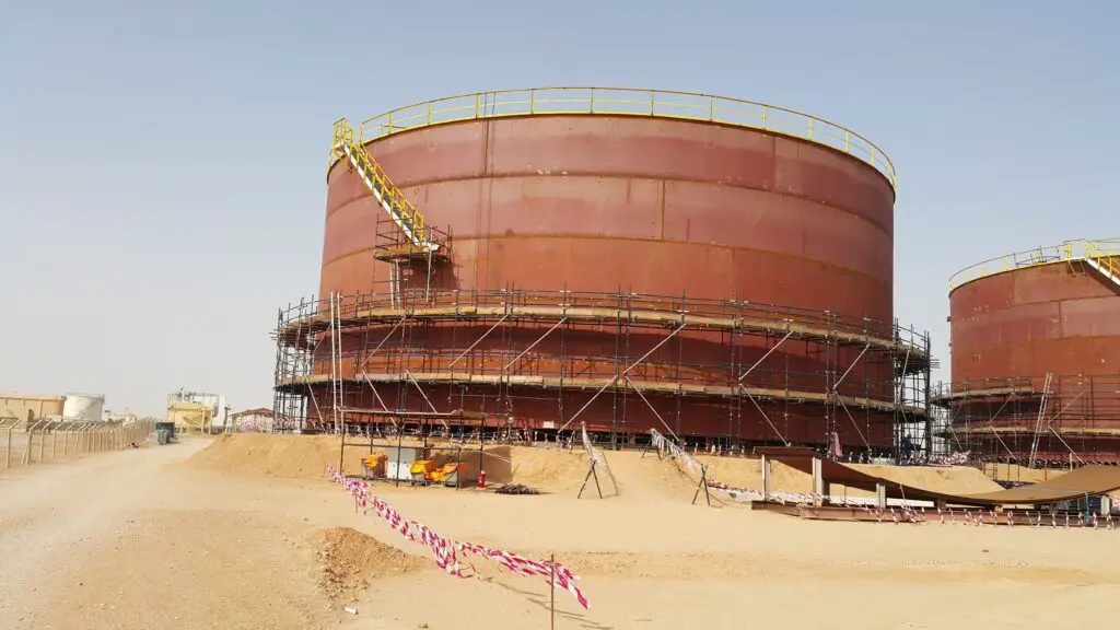
3. Storage Tank Erection
There are two methods for storage tank erection:
- the Jacking method &
- the conventional method.
The conventional method is tough & unsafe as compared to the jacking method that’s why the jacking method for Tank erection is used everywhere.
In the jacking method, we calculate the overall weight of tank ages except for the bottom & deck, and accordingly, jacks are used. The number of jacks to be used is directly subjected to the weight of the tank to be lifted.
3.1 Laying of Storage Tank Annular Plate
- Check the extent of the foundation as per specification Latest API 650 clause 8.4.2. After getting clearance for annular plate laying, mark the 0 degrees, 90 degrees, 180 degrees, and 270 degrees coordinates on the inspiration from the point of reference.
- Lay the annular plate as per the approved drawing. Out radius of the annular plate shall be on the positive side (5 to 10 mm.) so as to realize the ultimately required radius after weld shrinkage.
- The orientation of the annular plate joint shall be as per the approved drawing.
- Fit from the annular plate’s joints shall be administered using proper jigs and fixtures as shown in the drawing.
- Care shall be taken while fit-up, such that there shouldn’t be any gap between the annular plate and backing strip.
- Annular plate joint welding shall be administered by welding alternative joints in four quadrants.
- Qualified welders shall be engaged for the welding work consistent with WPS. If any defect is found, the defect weld shall be removed by grinding and re-welding and conducting the LPT check test.
- Repeat the sequence until the defect is cleared.
- Complete the welding, and clean the ultimate weld surface by wire brushing and grinding.
- Remove the jigs and fixtures that were used for the fit-up of the annular joint and grind the tack.
- Radiography shall be taken as per API-650 Sec-8.
3.2 Laying of Storage Tank Bottom Plate
- Lay the middle plate on the inspiration top as per the drawing.
- With the coordination of the Centre, plates lay rock bottom plates consecutively as per the drawing.
- Laps shall be maintained while the fit-up of a short seam and long seam as per drawing.
- Temporary tack welding is to be performed on the long seam to avoid uneven movements, while the fit-up and welding of the short seam are.
- Short seam welding is going to be administered alternatively to avoid distortion.
- After the completion of short-seam welding, remove the temporary tacks on the Long- seam by grinding to facilitate the long-seam fit-up. Short seam welding is going to be administered alternatively to avoid distortion.
- After the completion of short-seam welding, remove the temporary tacks on the Long- seam by grinding to facilitate the long-seam fit-up.
- Minimum laps shall be maintained while the fit-up of the long seam is as per the approved drawing.
- Joggling shall be administered by hammering wherever necessary. (Three plates Joining junction.)
- Before starting the welding, channels shall be tacked along the long seam to avoid distortion. After completion of shot seam welding long seam welding is going to be administered alternatively to avoid distortion. a professional welder shall be engaged and welding shall be performed as per the approved WPS.
- After completion of welding, thoroughly clean the weld joint by wire brushing and grinding.
- Sketch to annular plate joint shall be welded only after shell-to-bottom joint welding.
- All rock bottom plate joint vacuum box tests shall be administered as per the approved process and code specifications.
- If any defect is found, the defect weld shall be removed by grinding and re-welding and conducting the vacuum box test. Repeat the sequence until the defect is cleared.
3.3 Erection of Cone Roof Plates and Structures
- After completion of the highest two shell courses erection, fit-up, welding, and curb ring fit & welding shall be done.
- Erect the fabricated Centre Drum, Roof Truss, and cross girders as per drawing.
- Complete the welding of the Roof structure by approved welders and as per approved WPS. Erect and Lay the Roof plates on the structure as per the Drawing. While fit from the short seams and long seams Lap to be maintained as per the Drawing.
- Weld the short seams by welding the alternative joint or sequence mentioned within the drawing to stop the distortion.
- Provide proper support lengthwise of the long seam and weld the joints as per the drawing sequence.
- Roof Nozzles and top shell nozzles fit-up and welding shall be carried out as per the approved drawing and subsequently, it’s to be correlated with the priority piping drawing.
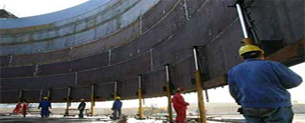
3.4 Erection of Storage Tank Shell
- After the completion of the welding of the Annular plates and bottom plates, mark the tank’s inner radius on the annular plates.
- Fix 25 Nos. of erection tools at equal intervals on the annular Plates & transfer the within tank diameter on the stools.
- The last 2 shell courses shall be erected by the conventional method.
- Balance shell courses shall be erected by the Jacking method.
- The rolled shell plates shall be shifted to the tank foundation area stacked around the periphery by using a crane.
- Proper care shall be taken while handling the rolled plates.
- Care shall be taken that the shell plate is erected to the diameter marked on the annular plate. Jigs and fixtures shall be used to align the shell plates.
- Complete the fit-up except for the ultimate joint which shall be fitted and welded after completion of the welding of the opposite joints. (To avoid shrinkage).
- Peaking shall be checked at the top, middle, and bottom of the vertical joints employing a Sweep board of 36” long. Plumpness shall be checked for the verticality of the shell course at every 60° and shall be within the tolerance (tolerance 1/200 of the entire shell height).
- For perfect verticality, channels shall be provided at regular intervals inside the shell course (3 to five meters), providing the channels shall facilitate the alignment of the of the shell course.
- Tack welds of the fitted vertical joints shall be ground smooth. Offer for inspection and obtain clearance from Engineer-in-charge for the vertical fit-up Complete the primary side welding by using qualified welders.
- Care shall be taken while welding to avoid peaking and therefore the roundness distortion.
- After completion of the first side welding, the back-chip shall be administered for sound metal from the other side of the weld by grinding.
- Back-chipped grooves shall be offered for inspection before starting the welding.
- Complete the 2nd side welding using qualified welders.
- Joint Nos. & welder No. shall be marked on both sides of the weld joint. Care shall be taken to avoid peaking and roundness distortion. Clean weld joints from each side by wire brushing and grinding. After completion of welding from each side remove all the temporary jigs and fixtures and flush grind the tacks. (Do the weld refill wherever required) and therefore the portion checked by M.P.T.
- Check the plumpness, circumference, and therefore the radius, and offer for inspection to the satisfaction of the Engineer-in-Charge. While erecting subsequent coarse 3 mm-thick spacers shall be kept between the shell courses.
- Erection channels shall be fixed between the jacked shell and erected shell course plates at regular intervals to align and hold the last shell in a vertical position.
- Check to peak at vertical joints of shell employing a sweep board of 36″wide, acceptable tolerance shall the as per API-650.
- Complete welding of last course vertical seam inside after getting clearance from the Engineer-in-charge. Back chip & welding shall be administered following as same as for other shell courses to the satisfaction of Engineer – in – Charge.
- After completion of welding, weld visuals, verticality, & circumference shall be verified and recorded to the satisfaction of the Engineer-in-Charge. Fit up the horizontal seam between the 2nd and 1st shell courses.
- Check the verticality of the last shell course, Verticality (plumpness) tolerance shall be as per API – 650 (maximum out of plumpness at the highest of the shell relative to the rock bottom of the shell to not exceed 1/200 of total shell height from top of the last shell to bottom).
- While welding, care shall be taken for banding and therefore the roundness. Back-chip shall be administered by grinding for the sound metal and to the satisfaction of the Engineer-in-Charge. Complete the 2nd side welding and clean the joint thoroughly from each side by grinding and wire brushing. Check banding, and plumpness, and record within the approved format to the satisfaction of Engineer-in-Charge.
- Offer welds visually to the satisfaction of the Engineer-in-Charge. Mark the RT spots as per the instruction of the Engineer-in-Charge, and complete the RT as per API-650 requirements. Offer the RT film for review to the Engineer-in-Charge, and if any repair occurs, the repair spot shall be repaired by grinding for the sound metal, Re-weld the repair spot as per code API -650 sec-8 requirements.
- Take the repair spot RT and re-offer for the inspection to the satisfaction of the Engineer-in-Charge. Spiral staircase erection shall be administered as per drawing, including brackets & avoiding fouling with welds.
- Remove all the temporary cleats and tacks by grinding. If any defect is found the defect shall be repaired by grinding the defect area for the sound metal plus 150mm from both ends of the defect.
- Conduct the DP test on the repair spot. perform the entire
- Process until the repair is cleared to the satisfaction of the Engineer-in-Charge.
- After completion of the shell to the bottom outside welding visual inspection is going to be administered to the satisfaction of the Engineer-In Charge.
- On completion of the shell-to-bottom welding/NDT and having completed all erection and welding work on the tank inside associated with the roof and roof structure, all unwanted materials, and scrap shall be far away from inside the tank.
- RT of the vertical and horizontal joints shall be completed.
- Sketch to annular plate joint fit-up shall be administered after completing the shell-to-bottom welds.
- A vacuum box test shall be administered for the rock bottom plate short seam, long seam, and sketch to the annular plate joint. If any repair occurs, an equivalent shall be repaired and re-tested as per the approved procedure and API-650.
3.5 Installation of Tank Appurtenances
- Flanges to pipe joint shall be prefabricated and required NDT shall be completed before erection.
- Mark the nozzle location as per the drawings. Cut the openings by gas cutting after proper Inspection-by-inspection authority.
- Erect the nozzles as per the orientation & the elevation shown within the drawing. Install RF. pads wherever required before nozzle erection.
- Suitable jigs & fixtures shall be provided to stop the distortion during the welding.
- Orientation, elevation, & projection shall be maintained as per the drawing and offer for the inspection clearance. Proper care shall be taken for welding by providing jigs & fixtures to stop distortion.
- Welding shall be as per WPS and to be welded by the qualified welder.
- The man-hole neck shall be fabricated, and therefore the longitudinal joint shall be radiographed. All the RF Pad welds shall be pneumatically tested at a pressure of 1.05 Kg/Cm². The pneumatic test shall be administered to the satisfaction of the engineer in charge.
- All the shell nozzles finally weld from each side and RF Pads welds shall be inspected visually and by LPT, to the satisfaction of the engineer-in-charge.
Storage tank construction is a complex and multifaceted process that requires careful planning, design, and execution. Whether for oil and gas, chemicals, or other industries, the principles of storage tank construction remain critical for protecting resources and the environment while ensuring the safety of personnel and the surrounding community.
Differences Between Jacking and Conventional Methods of Tank Erection
The major differences between the storage tank erection methods by conventional and jacking methods are provided here: Storage Tank Erection: Conventional vs Jacking Method