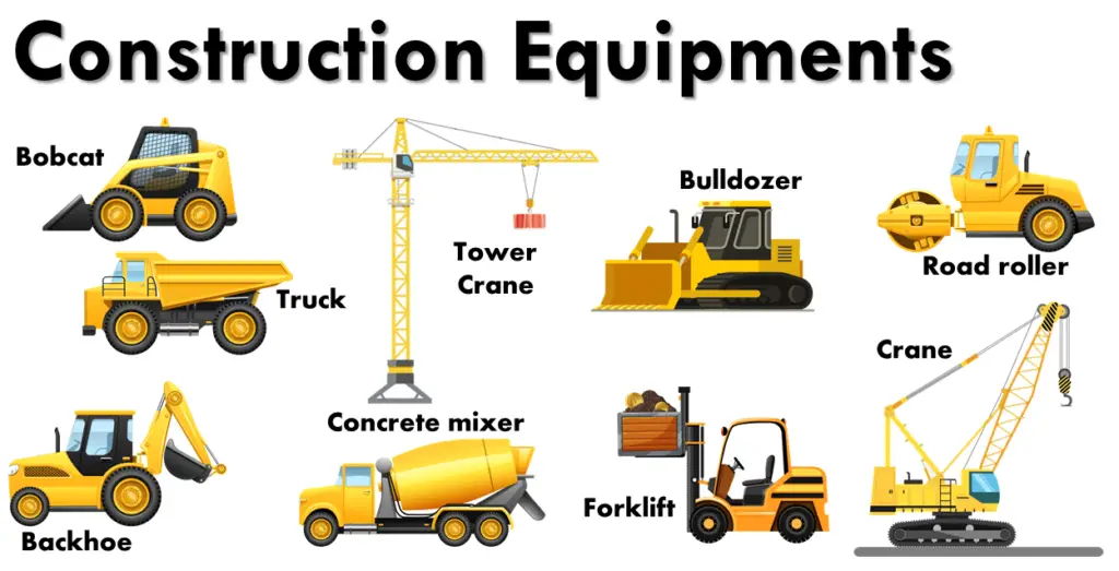
Construction Equipment plays an important role in the construction process. Proper selection of equipment is necessary for the Economy, Quality, Safety, Speed, and Timely completion of the Project. A wide range of construction equipment is used in the construction industry to help to perform jobs in a smooth and easy way. Even though most construction equipment is quite common among industries, there could be the use of specialized construction equipment depending on the requirement. In this article, We will list down the name of construction equipment that is used frequently in Oil & Gas Projects. Fig. 1 below shows examples of typical construction equipment.
Types of Construction Equipment
Broadly, Construction Equipment is classified into the following groups:
Earth Moving equipment
Road making equipment
Hauling equipment
Piling equipment
Concrete Equipment
Quarry equipment
Pneumatic equipment
Lifting and handling equipment
Slip form equipment
Welding equipment
Shop Fabrication and Testing equipment
Pipe laying equipment
Construction equipment for electrical installation
Floating Equipment for marine works
Tunneling equipment
Other miscellaneous equipment
Earthmoving Equipment
Earthmoving equipment performs the task of digging and moving the earth. The name of construction equipment that falls under the earthmoving equipment category are:
The hardness of a material is its ability to resist localized permanent deformation, penetration, scratching, or indentation. So, it is an important parameter in engineering. Hardness testing provides a means to quantify the hardness of a material, and it is a key element in many quality control procedures and R&D work. Several methods are available for hardness testing. However, Brinell, Rockwell, Vickers, Knoop, Mohs, Scleroscope, and the Files test are the most widely used hardness tests. In this article, we will learn about the Brinell Hardness Test, its procedure, related formulas, applications, advantages, and standards.
1. What is the Brinell Hardness Test?
The Brinell Hardness Test method is the most commonly used hardness measurement technique in the industry. In the Brinell Hardness Testing, the hardness of a metal is determined by measuring the permanent indentation size produced by an indenter. Harder materials will generate shallow indentations while softer materials will produce deeper indentations. This test method was first proposed by Swedish engineer Johan August Brinell in 1900 and according to his name, the test is popular as the Brinell Hardness Test. This test is also popular as the Hb hardness test or the BHN hardness test.
ASTM E10 defines the Brinell hardness test as an indentation hardness test performed in a verified machine by forcing a tungsten carbide indenter into the test material surface.
2. Brinell Hardness Test Procedure
The Brinell Hardness Test is performed in a Brinell Hardness Test Unit. In this test method, a predetermined force (F) is applied to a tungsten carbide ball of fixed diameter (D), held for a predetermined time period, and then removed. The spherical indenter creates an impression (permanent deformation) on the test metal piece. This indentation is measured across two or more diameters and then averaged to get the indentation diameter (d). Using this indentation size (d), the Brinell Hardness Number (BHN) is found using a chart or calculated using the Brinell hardness test formula.
The equipment used for Brinell Hardness Testing is:
Brinell Hardness Testing Machine
Indenter Sphere, and
Brinell microscope to measure the generated impression.
2.1 Brinell Hardness Testing Machine:
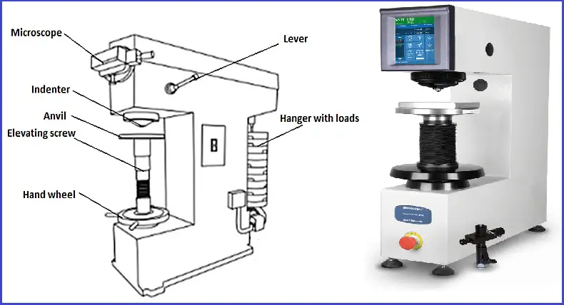
The Brinell Hardness Testing Machine (Fig. 1) consists of a loading system that includes leavers, weights, a hydraulic dashpot, and a plunger enclosed in the body of the machine. The test material is kept on the adjustable anvil. Using the lever, the spherical ball indenter descends on the material with a predecided force that can be read on the screen. The machine typically has a hydraulic system that ensures the load is applied uniformly and can be held for a specific dwell time.
Fig. 1: Brinell Hardness Testing Machine
For softer metals, the force used is less than for harder metals. The force value varies from 1 kgf to 3000 kgf. Common test forces range from 500 kgf often used for non-ferrous materials to 3000 kgf for steels and cast irons.
2.2 Indenter Sphere
The indenter used in the Brinell hardness test is usually a hardened steel or carbide ball. There are four sizes of the indenter used for the Brinell hardness test. They are 1 mm, 2.5 mm, 5 mm, and 10 mm in size. The choice of diameter depends on the hardness of the material being tested.
To obtain the same BHN with different ball diameters, geometrically similar indentations must be produced. It is possible if F/D2 is maintained constant.
2.3 Measurement Tools
After the indenter is removed, the diameter of the indentation is measured using optical equipment, such as a microscope or a camera system.
3. Steps for The Test
3.1 Sample Preparation
To ensure accurate results, the test surface must be flat, smooth, and free from contaminants. Surface preparation may involve grinding or polishing the material.
3.2 Conducting the Test
Positioning the Sample: Secure the material sample in the testing machine.
Selecting the Indenter: Choose the appropriate ball diameter based on the material hardness.
Applying the Load: Gradually apply the specified load using the machine. The load should be maintained for a predetermined dwell time, usually between 10 to 15 seconds.
Removing the Load: After the dwell time, the load is removed carefully.
Measuring the Indentation: Use the appropriate measurement tool to accurately determine the diameter of the indentation.
3.3 Calculation of BHN
Using the measured values of F, D, and d, apply the BHN formula as per Fig. 2 to calculate the Brinell Hardness Number.
4. Brinell Hardness Test Formula
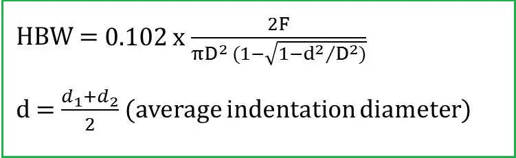
Once the average indentation diameter is measured the Brinell Hardness Number (BHN or HBW) can be calculated using the following Brinell hardness test formula:
Fig. 2: Brinell Hardness Test Equation
Here,
F=Applied force, in kgf
D=diameter of indenter, in mm
d=diameter of indentation, in mm
Note that, the term HBW stands for Hardness Brinell Wolfram carbide. Wolfram carbide (= tungsten carbide) underlines the use of tungsten carbide balls, as opposed to the (softer) steel balls previously used (HBS).
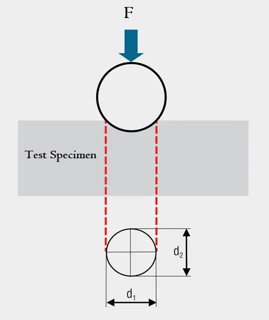
Fig. 3: Brinell Hardness Test
The minimum Test Specimen thickness is at least 10 times the indentation depth as per ASTM standard and the same is at least 8 times the indentation depth as per ISO standard.
5. Unit of Brinell Hardness
The BHN or HB values are mostly reported using only the number. So, it seems there is no unit for the Brinell Hardness Number. But that is not true. The unit of Brinell hardness is kgf/mm2. The same is quite clear from the above-mentioned HBW formula. The force term (F) in the numerator has a unit of kgf and the diameter term (D) has a unit of mm. In the SI unit system, the unit of hardness is N/m2
6. Specifying Brinell Hardness Number
While specifying a Brinell hardness number (BHN or HB), the test conditions used to obtain the number must be specified. The standard format for specifying is “HBW 10/3000”. “HBW” refers to a tungsten carbide ball used as an indenter, as opposed to “HBS”, which means a hardened steel ball. The “10” is the ball’s diameter in millimeters. The “3000” is the force in kilograms force.
Sometimes, the Brinell hardness is also specified as “XXX HB YYD2” where
XXX is the force to apply (in kgf)
YY specifies the material type (5 for aluminum alloys, 10 for copper alloys, 30 for steels).
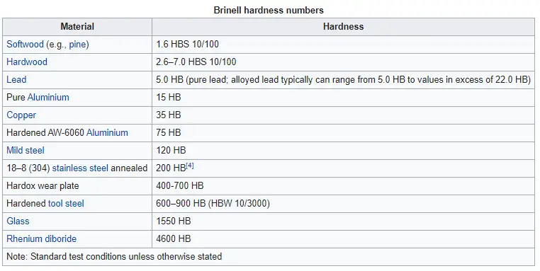
Thus the Brinell hardness of a typical steel could be written: 250 HB 30D2. The following image from Wikipedia provides some typical Brinell Hardness Values of common materials.
Fig. 4: Typical Brinell Hardness Values
7. Requirements for Brinell Hardness Testing
Before the test, the sample must be cleaned thoroughly. Preferable if the test surface is machined, ground, and polished to get better indentation measurement.
Proper indenter (Steel ball or carbide Ball) as per requirement needs to be selected.
The applicable force needs to be determined beforehand.
The load on the specimen is to be maintained for the exact period of time.
The indents must be positioned to keep sufficient clearance from the specimen edge and between the individual indents.
8. Standards for the Brinell Hardness Test
The widely used standards for the Brinell Hardness Test in industries are:
ASTM E10: ASTM E10 specifies the test method for the Brinell hardness of materials, ensuring consistency and reliability in testing across various industries.
ISO 6506: The Brinell hardness test is standardized under ISO 6506. This standard outlines the testing procedures, equipment specifications, and calculation methods.
JIS Z 2243
9. Factors Influencing the Brinell Hardness Test Results
The measured value of BHN can be influenced by the following factors:
9.1 Material Properties
The microstructure and hardness of the material can significantly affect the indentation size. Softer materials will have larger indentations, while harder materials will show smaller indentations.
9.2 Load Selection
The load must be appropriately selected based on the hardness of the material. Too high a load can cause excessive deformation, while too low a load may not produce a measurable indentation.
9.3 Indenter Size
The diameter of the indenter influences the test results. A larger indenter can provide a more representative measurement for materials with a heterogeneous structure.
9.4 Dwell Time
The duration for which the load is applied (dwell time) can affect the indentation size, especially in materials that undergo time-dependent deformation (creep).
10. Advantages and Disadvantages of the Brinell Hardness Test
The Brinell Test method has many advantages:
The hardness of rough samples can be measured which is difficult with other methods.
Application of high test load (up to 3,000 Kg) is possible.
Wide measuring range due to availability of a range of indenter sizes and loads
A Brinell hardness tester can determine the hardness of all types of metals.
Provides reliable results.
The formula for calculating BHN is straightforward, making the test accessible for various industrial applications.
However, the Brinell test method has some disadvantages as well:
There could be measuring errors due to the use of optical instruments.
Surface imperfections can interfere with the test result if the surface is not prepared thoroughly.
The requirement of a flat surface makes this test redundant for cylindrical surfaces.
For materials above 650 HBW 10/3000, the Brinell hardness test is not recommended.
The process can be relatively slow compared to other hardness testing methods, especially in high-throughput environments.
11. Brinell vs Rockwell Hardness Test | Difference between Rockwell and Brinell Hardness Test
The main difference between the Brinell and Rockwell Hardness Test is provided in the table below:
Brinell Hardness Test
Rockwell Hardness Test
In Brinell Hardness Test the indenter is a spherical Tungsten Carbide Ball
For the Rockwell Hardness Test, the Indenter is a Small Steel Ball (HRB) or a diamond cone (HRC)
Hardness greater than 650 HB can not be measured with the Brinell Scale setup.
There is no such limitation in Rockwell hardness testing.
Large Indentation
Small Indentation
The Brinell hardness test measures the diameter of the indentation to calculate the hardness value.
Depth of indentation is measured for calculating Rockwell hardness.
High Load
Lower Load
The Brinell hardness testing method is a comparatively slow method. So, the method is time-consuming.
Rockwell hardness testing is a Quicker process. Hence, it is an efficient method.
Surface preparation is required for Brinell hardness testing.
No surface preparation is required for Rockwell hardness testing.
Generally used for thicker materials.
Suitable for thin and thick materials.
Versatile, suitable for a wide range.
Best for softer metals and alloys.
The main governing standard for Brinell Hardness Testing is ASTM E10.
The main governing standard for Rockwell Hardness Testing is ASTM E18.
Table 1: Brinell vs Rockwell Hardness Test
12. Brinell, Rockwell, and Vickers Hardness Conversion Table
The approximate conversion of Brinell, Rockwell B & C, and Vickers hardness is provided below for sample only. One more column indicating approximate equivalent tensile strength is also added.
13. Relation between Brinell Hardness (BHN) and Tensile Strength
Note that, There is no concrete method of accurately converting the Brinell hardness numbers on one scale to Brinell hardness numbers on another scale, or to other types of hardness numbers, or to tensile strength values. Such conversions are, at best, approximations and, therefore should be avoided.
In general, with an increase in Brinell Hardness values the tensile strength also increases. There is an approximate formula that can be used to convert BHN to tensile strength (UTS) or vice versa. The relationship between BHN and UTS is based on Meyer’s index (n) from Meyer’s law devised by Eugene Meyer.
The approximate formula for calculating tensile strength for known BHN values for carbon steel material is given as follows:
Tensile Strength, PSI=515 X BHN (For Brinell numbers <= 175)
Tensile Strength, PSI=490 X BHN (For Brinell numbers > 175)
Note that, the above approximate formulas are not applicable for nonferrous metals.
14. Table of Brinell Hardness Numbers
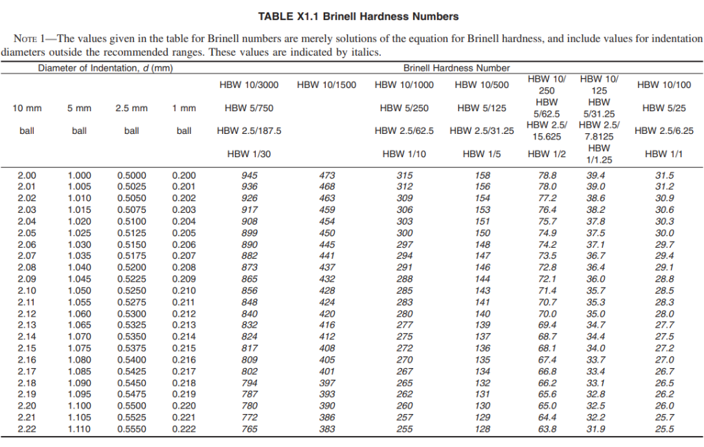
The Brinell Hardness Numbers Table can easily be generated by solving the formula given above for different load and diameter conditions. A typical table of Brinell hardness numbers is produced in Fig. 5 below from ASTM E10 Table X1.1.
Fig. 5: Table of Brinell Hardness Numbers per ASTM E10
15. Uses of Brinell Hardness Test
Some of the applications of the Brinell hardness test are mentioned below:
Industrial Applications: Industries such as automotive, aerospace, and construction utilize the Brinell hardness test for product validation and performance assessment.
Quality control: The Brinell hardness test is commonly used in manufacturing and quality control to ensure that materials meet specific hardness requirements. For example, it can be used to test the hardness of steel components used in automotive, aerospace, or construction applications.
Material selection: The Brinell hardness test can be used to compare the hardness of different materials and to select the most appropriate material for a specific application. For example, it can be used to compare the hardness of different types of steel or to compare the hardness of steel and aluminum alloys.
Heat treatment evaluation: The Brinell hardness test can be used to evaluate the effectiveness of heat treatment processes on metals. For example, it can be used to determine whether a specific heat treatment has achieved the desired level of hardness.
Research and development: The Brinell hardness test is also used in research and development to investigate the properties of new materials and to develop new materials with specific hardness properties.
Failure analysis: The Brinell hardness test can be used in failure analysis to determine the cause of material failures. For example, it can be used to determine whether a component can fail due to insufficient hardness or to identify areas of a component that have been subjected to excessive stress.
Overall, the Brinell hardness test is a valuable tool for measuring the hardness of materials and is widely used in a variety of applications in industry, research, and development.
16. Frequently Asked Questions
What is the Brinell Hardness Scale?
Brinell hardness scale is a designation to identify the specific combination of ball diameter and applied force used to perform the Brinell hardness test.
What is the Brinell hardness test?
The Brinell hardness test is a method used to measure the hardness of materials, particularly metals and alloys. It involves pressing a hard spherical indenter into the material under a specific load and measuring the diameter of the resulting indentation.
What types of materials can be tested with the Brinell method?
The Brinell test is suitable for a wide range of materials, particularly metals and alloys with coarse or uneven grain structures. It is commonly used for steel, cast iron, and other metals.
How long should the load be applied during the test?
The load should typically be applied for a dwell time of about 10 to 15 seconds, although this can vary based on the material being tested.
Can the Brinell hardness test be performed on small samples?
The Brinell test is generally not recommended for small or thin samples due to the size of the indentation produced. For such cases, alternative methods like Rockwell or Vickers hardness tests may be more appropriate.
What standards govern the Brinell hardness test?
The Brinell hardness test is governed by several standards, including ISO 6506 and ASTM E10, which outline the procedures, equipment specifications, and calculation methods.
Is the Brinell hardness test a destructive test?
Yes, the Brinell hardness test is considered a destructive test because it leaves a permanent indentation on the material being tested.
What industries commonly use the Brinell hardness test?
The Brinell hardness test is widely used in industries such as metallurgy, automotive, aerospace, and construction, primarily for quality control and material selection purposes.
In recent times, FEA or Finite Element analysis is the most widely used method for solving engineering and mathematical models. Using Finite Element Analysis or FEA, a physical phenomenon is simulated to find close to real behavior. FEA is developed using a numerical mathematic technique known as the Finite Element Method, or FEM. Finite Element Analysis is a computer-aided numerical analysis program that solves complex problems in many engineering fields. The complex problems might be
thermal analysis such as steady-state and transient,
structural analysis such as stress, vibration, and deflection, and
fluid dynamic analysis such as turbulent and laminar flow.
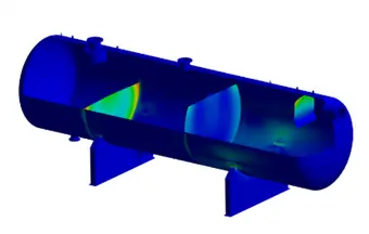
Basically, with the help of this method, one can find stress distribution in complex geometries. It provides solutions to problems that are anyway difficult to obtain. In other words, the finite element analysis method is a faster way to get solutions to problems that are difficult to solve.
Fig. 1: Graphical Representation of an Equipment in an FEA Tool
FEA Meaning
In simple language, finite element analysis or FEA is the right approach to problems like when a force is applied on a solid, what could be the values of the displacements, strains, and stresses at each material point? The most logical answer is that FEA tells us where a particular object can break or strain to make it unusable. The most common problems solved by FEA involve determining stress intensity factors of a load on an object. This can be in any form such as solid mechanic analysis, thermal analysis, structure analysis, dynamics, and electrical analysis.
How Does Finite Element Analysis Work?
Finite element analysis software creates a mesh of millions of smaller elements to create the complete structural shape. The effect of the parameter for example internal pressure force is assessed on each element and then combined to arrive at the final result for the full equipment or structure.
Importance of Finite Element Analysis or FEA
Finite Element Analysis is the basis of modern software simulation with the results shown on a computer-generated color scale. There are some theories that state that finite element analysis has its roots in the 16th-century work of Euler, which is the earliest mathematical paper describing the technique dating back to Shellback’s work of 1851. This method was then developed by engineers from various industries around the world thereby helping the user to solve a large number of structural mechanic problems, basically in civil engineering and aerospace. The very first development of finite element analysis for real applications began in the 1950s.
Finite element analysis is important as it plays a major role in the product design and development process. It has the capability to identify where a problem can occur in a product or an object. This method uses mathematical calculations to solve the problem areas of an object, thereby saving engineers the time and effort required to build a physical prototype. On the other hand, prototype tests as compared to FEA do not provide numerical calculations which makes the product development process quite long. Finite element analysis software saves both time and effort for the engineers. The importance of this software lies in its ability to take a complex design and highlight the efficiency and robustness of the design. With the help of FEA, engineers can quickly understand early information on system failures and their improper design techniques.
The finite element analysis method is used in almost all engineering disciplines. It is known to be the alternative to the experimental test method being set in many standards. It works in such a way that a user can reach an approximate solution to any complex problem by dividing the component into smaller or finite elements.
Advantages of FEA
There are numerous advantages of FEA:
It is used in many engineering disciplines for the estimation of structural behavior and strength, design optimization, modeling, and simulation.
It is used in piping design where rigidity is a governing factor instead of flexibility.
There are a few limitations of beam element software like CAESAR II that experienced engineers and designers are aware of. CAESAR II may indicate stress or sometimes loading issues that may not exist and sometimes fail to point out the issues.
The application of FEA software is created to address problems related to piping and pressure vessel that CAESAR II and code limitations cannot resolve.
It helps in solving problems related to buckling and plasticity.
Buckling is a concern where Piping and pressure vessel geometries have a large D/t ratio or external pressure. In this case, FEA analysis of pressure vessels helps to analyze buckling and elastic-plastic collapse study.
Thermal gradients through the wall often result in significant stresses. In this case, it also, FEA helps in analyzing steady-state transient thermal stresses.
Optimal use of a model.
It gives comprehensive result sets by generating a physical response of the system at any location which might have been neglected in the analytical approach.
It provides rapid calculation time and low investment for most applications.
It provides engineers with simultaneous calculation and visual representation of a number of physical parameters like stress, and temperature and helps the designer to quickly analyze performance and necessary modifications.
It helps to gain a thorough understanding of the behavior of the product and the nature of the application.
An FEA tool improves the quality of user analysis for critical service lines.
FEA tool automatically includes coverage of B31J2017 ASME B31 code in the analysis and hence gives more accurate flexibility and SIF factors for necessary components.
Finite Element Analysis software
There is numerous finite element analysis software available in the market and it’s really difficult to choose. Widely used engineering finite element analysis software are:
ANSYS: US-based full CAE software package.
AutoDesk CFD: Finite Element Analysis software of Autodesk.
Nozzle-Pro: By PRG
ROHR2fesu: Finite Element Analysis of substructures in ROHR2.
PASS/EQUIP Nozzle-FEM: By PASS
Abaqus: Advanced Franco-USA software from SIMULIA, owned by Dassault Systemes
MATLAB: MATLAB Toolbox for solving structural, thermal, electromagnetics, and other general PDEs
Solidworks FEA Simulation
RFEM: 3D finite element analysis software
Advance Design: BIM software for FEM structural analysis, including international design eurocodes.
OpenFOAM: By the OpenFOAM Foundation
Simscale: German 100% web-based CAE platform
VisualFEA: FEA software for structural, geotechnical, heat transfer, and seepage analysis.
RoboLogix: By Logic Design Inc.
COMSOL Multiphysics: COMSOL Multiphysics Finite Element Analysis Software (formerly FEMLAB)
IVRESS: By Advanced Science & Automation Corporation
Altair HyperWorks Suite: By Altair Engineering
Advanced Simulation Library: By Avtech Scientific
SU2: By Stanford University
PRO/II Process Engineering: By AVEVA
Ingrid Cloud: By Adaptive Simulations
Nastran: Originally developed for NASA, now available commercially from several software companies
Out of the above ANSYS is the most widely used FEA software. For Nozzle load checking Piping and Mechanical Engineers use the NozzlePRO or PASS/EQUIP Nozzle-FEM package.
When to use the CAESAR II FEA module
Caesar II FEA module can be used during the following circumstances:
To check nozzle loads where WRC 107/297 are often inaccurate and not comprehensive.
When the d/D ratio is greater than 0.5, that is, to examine large branch intersections.
For piping having D/t ratios of more than 100.
To calculate accurate operating bolt load while performing flange analysis.
To accurately estimate SIF and flexibility for piping analysis.
Piping systems that use thin-walled welding tees.
To determine external loads on saddle-supported vessels.
When a piping system requires a more accurate spring hanger design.
Piping systems that are connected to sensitive or rotating equipment.
Piping Systems are anticipated to have operating cycles of more than 7000.
When there is short or stiff piping in a system where k factors have a large impact.
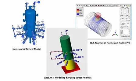
When a piping system has questionably high calculated stresses.
Fig. 2: Different Graphical Representation in Caesar II and Nozzle Pro
Examples of Finite Element Analysis
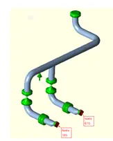
We will explain the results by taking an example of a piping system as shown below in Fig. 3:
Fig. 3: Two Pump Stress Model
There are two pumps. Both of these pumps combined to a common header as shown in Fig.3 Here we have used FEATools to reduce the loads on the nozzles of pumps A and B at odes 120 and 570. The load on the nozzle having node no.120 is FX=1140lb and for node no. 570, FX= 3626lb. The question here is whether will FEA Tools help in Caesar II analysis.
SIF and flexibilities can be refined to new factors at the tee location with the help of FEA Tools, hence we will see if this results in reducing the loads at the pump nozzles.
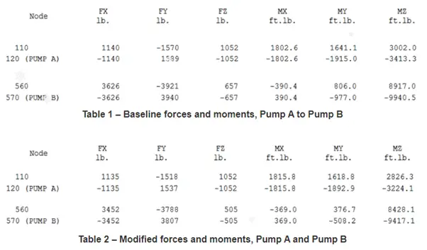
Table 1 in Fig. 4 shows the global element forces for pumps A and B before using FEA Tools and Table 2 shows the global element forces after using FEA Tools respectively.
Fig. 4: Tabular Comparison of Results with and without FEA
Conclusion: SIF and Flexibility are updated based on ASME 07-02, with suitable changes to appendix D of the B31 codes. Also, it is quite clear that there is a lot of incorrect SIF from ASME B31J that has been shown and provide the user with incomplete guidance. Further to be noted, for branch connections, the omission of k-factors allows for ASME 07-02 to correct these errors. Basically, the use of FEA Tools does not really mean that it can reduce the nozzle loads until the stresses reach the allowable stress.
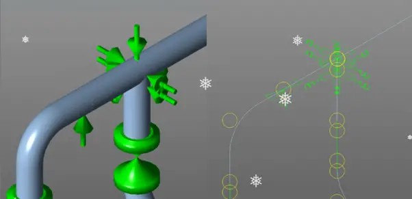
Fig.5 shows the added restraints and spring at the branch connection as per the guidelines in 07-02 of FEA Tools.
Fig. 5: ASME 07-02 Tee Conversion Detail
To the center point of the tee, each branch is connected by a series of connecting nodes with k factors as per the allowable in ASME 07-02. The purpose of the added spring would be to reduce the stress caused due to thermal strain in a piping system. Such types of piping systems are best applicable with expansion joints or expansion loops when no other solutions are successful or not ideal in Caesar II analysis. Hence an analyst can conclude that FEA Tools itself cannot reduce the loads significantly enough to create that much difference in the equipment’s overall loads. One must think of other options to reduce the loads in the pump nozzles.
ASME B31J the engineer should use stress intensification factor and flexibility factor data from the code in the absence of applicable data. In order to supply this applicable data to CAESAR II, FEA-Tools uses the results of the latest research, analysis, and testing.
FEA vs FEM
Are FEA and FEM the same or are there any differences!!
FEA (Finite Element Analysis)
FEM (Finite Element Method)
FEA is the application of FEM
FEM is the cause or reason. It is the background theory behind FEA software.
This is the same as FEM. Engineers involve FEM to predict the performance of their designs in different conditions.
A numerical technique that is used to get approximate solutions of the partial differential equations.
It is related to solids and can be used for anything.
Here the analysis could be solid, fluid, thermal, or electromagnetic.
It is most popular in industries.
It is popular in universities.
It covers a wide area of problems related to heat transfer, the strength of materials, vibrations, and acoustics.
It includes the Galerkin method, numerical integration methods, and weighted residual method to solve problems.
It is learning basic FEM concepts, and solid mechanics and using them in FEA software like ANSYS.
It is totally solid mechanics and finite elements and solving problems using coding or numerical methods.
Table: FEA vs FEM
Is Finite Element Analysis Difficult?
Knowing the full background theory and equations for performing the FEA analysis is really a difficult and time-consuming job. However, the application of FEA software is quite simple. All the required algorithms and equations are already fed into the software. So, FEA software is also similar to other stress analysis software.
Online Courses on Finite Element Analysis
To develop your strength in finite element analysis you can opt for the following online courses
With constant wear and tear happening in every piece of equipment in its running condition, efficiency reduction or equipment breakdown is bound to occur. One popular and widely used solution against these is Preventive Maintenance or Preventative maintenance. Such practices help in increasing the useful life of the equipment and they postpone the failure point. Studies have revealed that 78% of manufacturing facilities use preventive maintenance philosophy to some extent. In this article, we will explore the definition of preventive maintenance, its types, maintenance strategy, advantages, and disadvantages.
What is Preventive Maintenance?
Preventive Maintenance is a proactive planned maintenance philosophy involving regular and routine maintenance of equipment at a predefined interval to increase the lifespan of assets, equipment, and infrastructure. It reduces the likelihood of failure which in turn reduces the unplanned downtime of the operating plant. Through scheduled cleaning, lubrication, repairs, adjustments, oil changes, and part replacements, a preventive maintenance approach improves the operational output of equipment and machinery in a plant.
Preventive maintenance is not only routine maintenance of equipment. Knowing the lifespan of the equipment and maintaining accurate records of each and every inspection and servicing is also part of preventive maintenance. Using these records maintenance professionals can diagnose problems when they occur and decide the appropriate time to change parts. Various kinds of preventive maintenance software can help maintain and organize such data.
Types of Preventive Maintenance
Three types of preventive maintenance are widely popular in industries. They are:
Time-Based Maintenance
Usage-Based Maintenance and
Failure-Finding Maintenance
Time-Based Maintenance:
Time-based maintenance is also known as Calendar-based maintenance. This approach is followed for essential equipment. This maintenance approach ensures the equipment in optimal working condition and can be triggered at fixed time intervals regardless of the condition or usage of the asset. The time interval for maintenance must be decided based on the equipment manufacturer’s guidelines.
Usage-Based Maintenance:
In the Usage-Based Predictive Maintenance type, maintenance is typically scheduled after a certain usage of the equipment. Using meter readings or records, such maintenance is triggered. For example, normal automobiles may require servicing or engine oil change after every 10,000 km of driving.
Failure-Finding Maintenance (FFM):
Failure-finding preventive maintenance is an inspection to find or discover defects or failures in equipment. For example, a fire alarm is triggered to find out if the alarm is working and to find any fault in an alarm system.
Preventive Maintenance Examples
Depending on the type of industry, the examples of preventive maintenance will vary. However, whateverthe industry, preventive maintenance programs will always have the following three components:
It’s systematic
It’s performed routinely
Its purpose is to reduce or minimize failures
Typical examples of time-based predictive maintenance can be:
Replacement of filters after every six months.
Lubricate bearing after every three months.
Visual inspection of the conveyor belt each month.
Lubricating pumps every other week.
Replacing the RO filters each year.
Typical examples of usage-based predictive maintenance can be:
Maintaining equipment after producing 100 products.
Scheduling maintenance or servicing after every 60 working hours.
A typical example of failure-finding predictive maintenance is:
Starting the emergency sprinkler system periodically to find if the system is working smoothly to ascertain that it will work during an emergency situation.
A few other preventive maintenance examples could be
A thorough inspection of the vehicle before site visits.
Frequently maintain HVAC systems during summer.
Preventive Maintenance Plan or Philosophy
The preventive maintenance program is normally based on the following factors as listed below:
Impact of the worst-case scenario
lost production
Likelihood of failure
Cost involvement
Regulatory compliance
Workplace safety
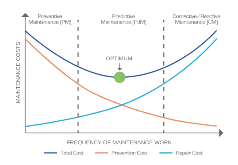
Preventive maintenance is performed when the benefits of the maintenance outweigh the risks and costs. The optimum frequency of the preventive maintenance plan is developed by plotting the maintenance cost vs maintenance frequency curve and finding a balance as shown in Fig. 1
Fig. 1: Preventive Maintenance Cost vs Frequency
There are a few steps for an effective preventive maintenance plan:
Finding the end purpose (Reduce downtime or repair cost, Increase production rate or asset availability)
Identifying and Assessing the critical equipment and finding the cost and impact in case of failure.
Choosing the format for recording preventive maintenance goals (Manual, computerized, or advanced software-based)
Creating the preventive maintenance plan and schedules like assigning personnel, tasks, prioritization, and recording.
Tracking, reviewing, acting, and adjusting.
Advantages of Preventive Maintenance
A number of benefits are received through proper preventive maintenance planning:
Prolonged life of company equipment before failure.
Fewer errors in day-to-day operations
Less unplanned downtime.
Increasing productivity and efficiency
Less unnecessary maintenance and inspections
Reduced risk of injury
Stronger work execution
Improved reliability of equipment
Fewer expensive corrective and emergency repairs
Reduced health, injury, and safety risks
Improving audit and regulatory compliance with extensive documentation
Less Energy Consumption
Optimized maintenance planning and resource allocation
Better margins and profits
Disadvantages of Preventive Maintenance
A few potential disadvantages associated with a Preventive Maintenance schedule could be:
Budget Constraints (High start-up and implementation costs)
Time-Consuming
The requirement for Additional Resources (spare parts, staff, etc.)
Organizational Difficulties
Requires planning
Applications of Preventive Maintenance philosophy
Preventive maintenance programs can be applied in all types of industries including:
Oil/Gas/Utilities
Chemical/Petrochemical
Power Plants
Metal/Manufacturing Industries
Country Clubs
Restaurants
Fleet Management
Property Management
Facility Management
Schools
Governments
Hotels, Hospitality & Restaurant Industry
CMMS Software:
For complex assets, it’s nearly impossible to record data and perform preventive maintenance without using the software. They are great tools for efficiently creating and scheduling digital work orders for preventive maintenance. CMMS or computerized maintenance management system is such a widely popular software. This software will automatically assign and alert the scheduled tasks based on the given input.
The main advantages of using CMMS over other modes of preventive maintenance programs are:
CMMS quickly sets up preventive maintenance schedules for any asset based on time or usage.
Track and manage all preventive maintenance work with an easy-to-use maintenance calendar.
Create PM checklists and attach them to the work orders.
Automate the administrative part of maintenance by sharing electronic work orders and letting the CMMS automatically log performed work.
Get instant access to all maintenance data which technicians can access via mobile devices even when out in the field.
Improve control over the spare parts inventory through automatic parts usage tracking and low in-stock notifications.
Keep a close eye on the preventative maintenance program by tracking important metrics and KPIs.
Reactive Maintenance vs Preventive Maintenance
The main differences between Reactive maintenance and preventive maintenance are listed in the table below:
Reactive Maintenance
Preventive Maintenance
Reactive maintenance provides the maximum utilization and production value from the equipment or asset.
Preventive maintenance calls for Lower equipment utilization
In reactive maintenance, the maintenance cost is higher after failure.
The maintenance cost is comparatively lower in preventive maintenance.
More unplanned downtime
Less Unplanned downtime
Reactive maintenance is Crisis based approach
Preventive maintenance is a preparation-based approach
Chaotic execution of work responsibilities
Organized execution of work responsibilities
Frequent failures
Longer life expectancy
Heavily people-dependent due to increased labor costs
Utilizes facility management software (FMS)
Reduced efficiency of the equipment
Efficient productivity
Reactive Maintenance vs Preventive Maintenance
Plant Maintenance Online Courses
To upgrade your knowledge about the aspects of plant maintenance, the following online courses can be referred to:
A project manager is a person who is responsible for the successful initiation, planning, design, execution, monitoring, controlling, and closure of a project. He is the overall leader and leads his team to ensure successful project completion within the scheduled time and budget. In every project, a project manager is a respected position and is held by key personnel of an organization. Depending on the type of industry, the role of a project manager may vary slightly but their main mission is to reduce project cost, maximize the efficiency of team members and increase company profits. From the start of the project till its completion, project managers are accountable for the success or failure of the project. The term “project manager” is widely used in information technology, construction, chemical, petrochemical, architecture, and oil & gas industries. Good project managers possess excellent entrepreneurial capabilities with various skill sets. In this article, we will explore the role of a project manager in detail.
Role of a Project Manager
A project manager runs the project on a day-to-day basis. He leads and manages the project team. They are persons with strong critical-thinking abilities and possess wonderful communication skills to solve problems as and when they arise. Project managers are well-informed about the project and always motivated. The role of a good project manager can be described as follows:
Proper Planning of Project Activities:
A project manager defines the project scope and strategically plans all project activities to prepare the project schedule. He must foresee the interdependency of each activity and prioritize accordingly. He must understand the resource allocation as per availability.
Organize the project team and encourage the members to perform their best:
A good project manager always keeps an eye on the project schedule and through his project team solves any major issues with disciplines in case of any deviation from the schedule. He encourages his team to solve any obstacle to meeting the commitments and brings the full potential of members. He never blames his teammates and establishes a perfect example of teamwork, understanding, and effectiveness.
Time Management:
A good project manager must be good at negotiating achievable deadlines and must interact the same with team members.
Deliverable Management:
Every project has a number of deliverables. Project managers must keep track that all deliverables are delivered within the agreed timeframe and budget.
Monitoring Project Progress:
In current times, money is normally related to progress. So, it is the project manager’s responsibility to monitor the progress through various tools and techniques and status reports. He must intervene in cases if progress is not as per planning.
Regular Meetings with Client, Project Team, and Discipline members:
Project managers must schedule regular meetings to understand what is going well and what is not. It will ensure the smooth working and progress of the project. Regular client meetings and meeting their expectations will build up good relationships with the client which will ensure more project wins from the same client in the future.
Managing Changes and Deviations:
A good project manager must track all the scope deviations and track those to discuss with the client regarding cost and schedule impact.
Execution:
The project manager should always be part of the successful execution of each project stage. He must understand each project phase through frequent, open communication with the project team members, discipline leads, and stakeholders.
Ensuring customer satisfaction:
Project managers must minimize uncertainty to avoid any unwanted surprises and involve stakeholders/clients as frequently as possible. Maintaining effective communication about project updates is always preferable.
Analyzing and managing project risk:
Good Project managers must meticulously identify the potential risks and evaluate those prior to the actual stage to reduce the impact.
Closing the project and ensuring Quality:
An ideal project manager must ensure all deliverables are following the quality system to ensure reduced rework at a later stage; It will increase the profitability of the company.
Skills of a Project Manager
A good project manager must have the following skills to work efficiently:
Proven Work Experience
Project Management
Developing and Tracking Budgets
Financial Analysis
Solid Organization Skills
Efficient Planning
Coaching
Supervision
Problem-Solving Skill
Staffing
Process Improvement
Decision making
Planning
Performance Management
Inventory Control
Excellent Communication Skill
Resource Management
Leadership Skill
Creative mindset
Analytical Skills
How to become a Project Manager?
If you are reading till this point means you are wondering about “How to become a project manager”. If you don’t have that huge experience and skills then you can follow the below-mentioned steps to fulfill your dream of becoming a project manager.
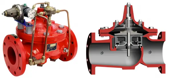
A deluge valve is a critical component of the deluge system used in fire protection services. During fire events, deluge valves are activated quickly and deliver a large volume of water over the protected area to extinguish the fire for protecting life and property. Because of this, deluge valves are known as the heart of a deluge system. They are activated by a detection system and operate as a system control valve. A deluge valve consists of an inlet, outlet, and a priming chamber. They can work in both vertical and horizontal installations. Deluge valves are widely used in Oil & gas industries, power plants, tank farms, foam systems, paper industries, car industries, petrochemical onshore and offshore installations, etc. Viking and Tyco are the industry leaders in manufacturing deluge valves. Fig. 1 below shows an image of a typical deluge valve.
Fig. 1: Typical Deluge Valve
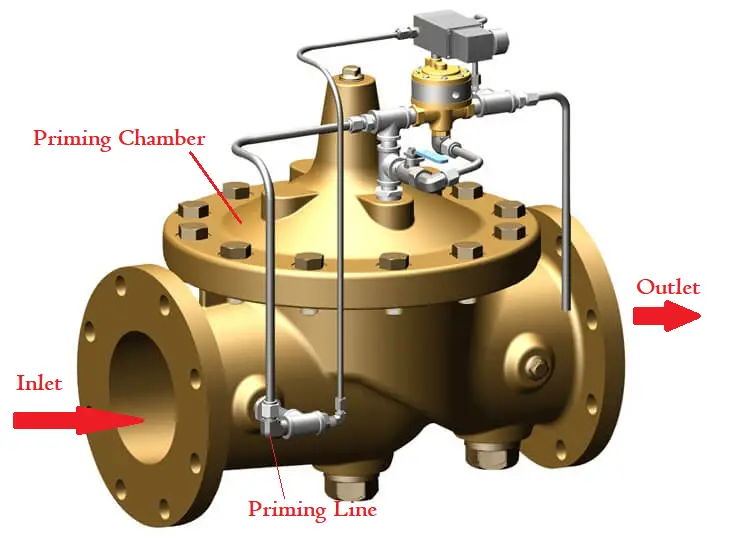
Working of a Deluge Valve
The deluge valve is a quick-acting, hydraulically operated diaphragm valve consisting of three chambers (Refer to Fig. 2), isolated from each other by the diaphragm-operated clapper and seat seal. Pressurized water is supplied to the priming chamber through an external bypass check valve and restriction orifice system during set position. The pressure of the water trapped in the priming chamber holds the diaphragm on the valve seat, keeping the valve closed.
Upon detection of fire, the pressure from the control chamber is released by a manual or automatic release device. So, the top chamber pressure of the deluge valve falls below the supply pressure forcing the diaphragm of the seat. Water from the inlet side flows into the piping network and alarm devices.
Fig. 2: Working of a Deluge Valve
Deluge Valve Types
Depending on the trim used in a deluge valve they are categorized as follows:
Basic Type
Dry Pilot Trim type
Wet Pilot Trim type
Electric Release Trim type
Test and Alarm Trim with Sprinkler
Basic Trim Type Deluge Valve:
Basic trim is required for all types of deluge valves regardless of the release system. Typical components of a basic trim-type deluge valve are the main drain valve, drip check valve, priming connection, emergency release valve, and pressure gauges.
Dry Pilot Trim Type Deluge Valve:
Dry pilot trim type deluge valves are known as pneumatic release type as it uses a pilot line containing dry air under pressure. The pilot line is connected directly to the top of the Positive Drain Actuator (PDA). The bottom of the PDA is connected to the top chamber of the deluge valve.
Due to the release of any of the release devices on detection of fire, the air pressure drops and the diaphragm of the PDA is lifted allowing the water to drain. This reduces the water pressure in the top chamber of the deluge valve and when the pressure in the top chamber reaches 50% of the supply pressure, the deluge valve opens.
Wet Trim Type Deluge valve:
A wet pilot trim type deluge valve uses a pilot line of closed sprinklers containing pressurized water for its operation. The water is supplied through the upstream side of the deluge valve, through a restricted orifice. All the release lines are connected to a common release line. When any of the release devices are released, the water pressure of the deluge valve top chamber falls to 50% of the supply pressure allowing the supply air to flow.
Electric Release Trim Type Deluge Valve:
As the name indicates, such type of deluge valve is actuated electrically. To activate an electric trim-type deluge valve, a solenoid valve is provided to drain the water from the valve top chamber. An electric alarm is activated by a pressure switch that shuts down the desired equipment or gives an indication for tripping to the control panel.
Test and Alarm Trim with Sprinkler:
Test and Alarm Trim with Sprinkler: Such trim is supplied along with the sprinkler alarm bell that bells on activation of the deluge valve. To test the normal operation of the sprinkler alarm bell, a test valve is provided.
Depending on the number of priming chambers two types of deluge valves are found.
Single chamber deluge valve and
Double chamber deluge valve
Single-chamber deluge valves are the traditional diaphragm-type valves with an inlet chamber connected to the deluge valve supply side and an outlet chamber connected to the fire suppression system side. Such deluge valves have only one prime chamber. These valves need low maintenance and provide an obstacle-free water path minimizing pressure loss.
Double chamber deluge valve design combines all the functions available on the traditional deluge valves with a fully redundant architecture and it provides higher reliability. Constituting two priming chambers, with their own diaphragm and actuation trim, such valves offer two independent waterways to the water spray system. Each priming chamber provides the nominal design waterway for the fire protection system. If one diaphragm fails, the other diaphragm opens allowing the hydraulic waterway for the correct operation of the water spray system.
Materials for Deluge Valve
A variety of different materials are used to produce a deluge valve depending on the requirement. Common deluge valve materials are