Von Mises Stress criterion is one of the widely used criteria for designing ductile material engineering components. To judge if a design is within design limits and will work safely for its design life, Von Mises Stress Criteria prove to be highly effective. Von Mises’s stress concept is developed from the distortion energy theory and a highly preferred failure theory used in the mechanical design industry.
This theory is devised by James Clerk Maxwell in 1865, but in 1913 it was rigorously developed by Richard Edler Von Mises, an Austrian Jewish scientist and mathematician. Accordingly, the theory is popular as Von Mises’s Stress theory. In this article, we will explore more details about Von Mises’s Stress.
What is Von Mises Stress?
Von Mises stress is an equivalent stress value based on distortion energy to decide if a ductile material will fail (yield or fracture) under a given loading condition. The Von Mises failure theory indicates that A material will fail if the Von Mises stress or effective stress of that material under load is equal to or greater than the yield limit of the same material under a simple uniaxial tension test.
Equation/ Formula for Von Mises Stress
Failure of any material is decided by a simple tension test. In this test when the material reaches the yield point, the material is considered as failed. Now failure by distortion energy or Von Mises Stress theory compares two kinds of distortion energy.
Case A: Distorsion energy for the actual case with complex loading conditions.
Case B: Distorsion energy for the same material in the simple tensile test during failure.
As per Von Mises’s Stress theory, Failure will occur if Case A>=Case B. Mathematically, this can be explained as below:
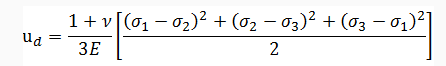
Distorsion Energy (ud) for the actual stress condition in terms of principal stress values (σ1, σ2, σ3)
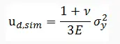
Again, the distortion energy for the uniaxial tension case at the time of failure is given as:
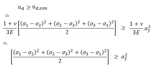
So, as per distortion energy theory,
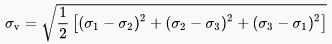
Now, the formula for Von Mises Stress, σv is given by
So, the above equation becomes, σv2>=σy2
So, the Von Mises failure condition can be simplified as follows:
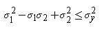
In the cases of plane stress, σ3 = 0. The von Mises criterion reduces to,
The failure envelope based on distortion energy or Von Mises Stress theory can be represented in two dimensions as follows:
Fig. 1: Failure envelope as per the distortion energy theory
Steps for solving problems using the Von Mises Stress Theory
To use the Von Mises Stress theory in solving problems the following steps are required to be followed:
Step 1: Calculate the three principal stresses (σ1,σ2, and σ3) using principal stress equations or Mohr’s circle method.
Step 2: Find out the Von Mises Stress (σv) following the equations mentioned above.
Step 3: Determine the value of the allowable stress (σy/N) of the material. σy is the Yield Strength and N is the factor of safety.
Step 4: Compare the value calculated in step 2 with the allowable value found in step 3. If the Value at step 2 is less than the allowable value calculated at step 3, then the design is safe as per the Von Mises stress theory.
Applications of Von Mises Stress Theory
During the mechanical design of elements, It is the duty of every engineer to keep the Von Mises Stress (σv) value below the yield strength (σy) of that material to make the design safe. This theory finds wide application in Finite Element Analysis.
In piping stress analysis and structural beam design, Von Mises Stress theory is applied to make the piping or structural beams safe from various loading conditions.
Difference between Von Mises’s theory and Maximum Shear Stress Theory
As distortion is always associated with shear stress; there are some similarities between both failure theories. The main differences between the Von Mises theory and the maximum shear stress theory are listed below:
The Von Mises theory predicts ductile yielding with more accuracy as compared to the maximum shear stress theory. It is more real and less conservative than the maximum shear stress theory and hence, product cost reduces.
Von-Mises theory uses all three principal stresses (σ1,σ2, and σ3) in its equation, while the maximum shear stress theory uses only two (σmax and σmin ).
Oil and gas, petrochemicals, and pharmaceuticals rely heavily on complex pipe systems to transport fluids, gases, and chemicals. In these applications, maintaining a tight seal, isolating equipment, and facilitating maintenance are essential. A Double Block and Bleed (DBB) valve is such a critical component that combines these functions to enhance safety and operational efficiency. In this article, we will explore what DBB valves are, how they work, their applications, and why they are crucial in modern industrial processes.
What is Double Block and Bleed Valve (DBB)?
A Double Block and Bleed (DBB) valve is a specialized type of valve designed to provide a superior level of isolation and safety in fluid control systems. Essentially, it combines the functions of two separate valves and a bleed port into a single, compact unit.
Double Block and Bleed Valve is a single assembly of two inline block valves and one bleed valve. A DBB valve is like having three valves in one. The task of three separate valves is performed by this assembly while saving huge space, installation, and maintenance time, weight, and cost.
The main aim of using a double block and bleed valve system is to ensure that the fluid from upstream and downstream does not reach other components of the system. So, engineers can easily bleed off or drain the remaining fluid from the intermediate section and execute maintenance, repair, or replacement work. In a double block and bleed system, isolation is achieved both from upstream and downstream flow or pressure. The bleed valve is used to drain the cavity created between two block valves.
Components of DBB Valve
Let’s break down its components and functions:
Two Isolation Valves:
The “double block” part of the DBB valve consists of two isolation valves, typically ball or gate valves, arranged in series. These valves, when closed, create a double barrier that isolates the downstream and upstream piping, ensuring no flow passes through.
Bleed Valve:
The “bleed” portion of the DBB valve is a smaller valve, often a needle valve, located between the two isolation valves. Its purpose is to allow controlled bleeding of fluid or gas from the cavity between the two isolation valves. This is crucial for verifying the integrity of the seals and for safely releasing pressure.
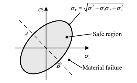
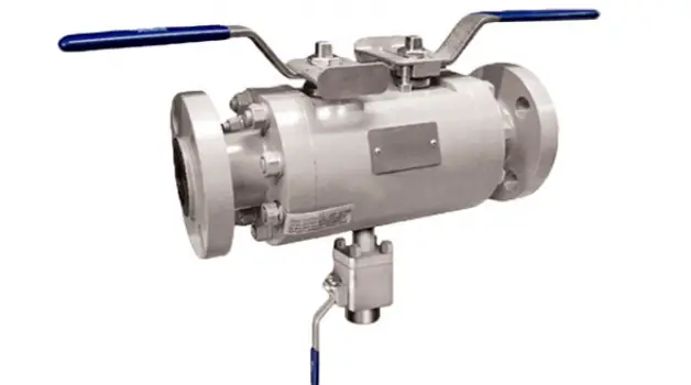
An NPS 3/4-inch or 1-inch bleed valve is installed between two block valves for venting or draining as shown in Fig. 1.
Fig. 1: Schematic of Double block and Bleed valve
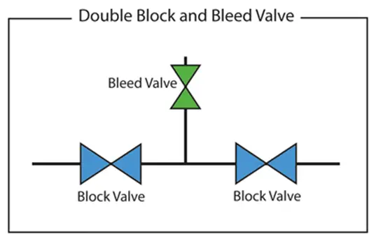
The image in Fig. 1 also serves as the double block and bleed valve P&ID symbol. In some companies, the P&ID system for the DBB valve can be represented as shown in Fig. 2.
Fig. 2: Double Block and Bleed Valve P&ID Symbol
Working Principle of a Double Block and Bleed Valve
Two block valves provide isolation from the upstream and downstream flows. A set of gate, ball, needle, or globe valves is normally used as the block valves that are placed back to back. In the center cavity of the two-block valves, a third valve known as the bleed valve is positioned. Fig. 3 shows a typical double block and bleed valve diagram.
Fig. 3: Double Block and Bleed valve diagram
The same double block and bleed arrangement can be obtained using three separate valves. But the single unit double block and bleed valve saves huge space, weight, installation time, and cost. Also, from the operation and maintenance viewpoint, single-unit double block and bleed valves are better as potential leak paths are significantly reduced in a single unit. Pressure drop is also minimized.
The operation of a DBB valve is relatively straightforward:
Normal Operation: In typical operational conditions, both isolation valves are open, allowing fluid or gas to flow through the valve as if it were a regular pipeline. The bleed valve remains closed.
Isolation: When maintenance or repairs are needed, the DBB valve offers a unique advantage. By closing both isolation valves, it effectively seals off the section of the pipeline in which it is installed. This isolation ensures that no fluid or gas can pass through.
Bleeding: After isolation, the bleed valve can be opened to release any trapped fluid or gas between the isolation valves. This step is crucial for safety and maintenance purposes, as it prevents pressure buildup that could be hazardous.
The main function of the bleed valve is
to drain/vent the cavity created between two isolation valves.
flow diversion
sampling and injection point connection
integrity or maintenance check connection to monitor leakage
Bleed valves can be vented to the atmosphere directly or a hose connection/piping system can be used for a closed disposal system.
Types of Double Block and Bleed Valves
Double Block and Bleed (DBB) valves ensure safe and dependable isolation of process fluids through a combination of block valves and a bleed valve. Depending on configurations, there are three types of DBB valves that are widely used:
Single valve systems,
Dual valve systems, and
Expanding gate valves.
Single Valve DBB
Single Valve DBB systems combine both block and bleed functions within a single valve body, featuring two separate sealing surfaces for effective isolation and a bleed function to vent trapped pressure. When closed, the primary and secondary seals create a double barrier, preventing fluid flow and ensuring isolation. A bleed port situated between the seals allows for the venting of any pressure or fluid once isolation is achieved, making the section safe for maintenance or inspection. Upon re-opening, the seals retract, restoring normal flow. The compact design of Single Valve DBB systems minimizes the need for additional piping and space, simplifying installation and maintenance. These systems are particularly useful in applications with space limitations and where moderate isolation integrity is sufficient.
Dual Valve DBB
Dual Valve DBB systems consist of two separate block valves and an independent bleed valve positioned between them, providing enhanced isolation integrity and maintenance flexibility. The first block valve is closed to prevent fluid from entering the isolated section, followed by the closure of the second block valve to create a dual barrier that ensures reliable isolation. Once both valves are closed, the bleed valve can be opened to vent any trapped pressure or fluid between the block valves, ensuring safety for maintenance personnel. During maintenance, the bleed valve is opened first to eliminate trapped pressure, followed by the opening of the block valves to restore normal operation. This setup offers enhanced safety through an additional layer of protection against leaks or failures and allows for independent maintenance of each block valve without compromising isolation integrity. Dual valve DBB systems are particularly suitable for high-integrity applications such as oil and gas pipelines, chemical processing plants, and other critical isolation scenarios.
Expanded gate valve DBB
Expanding gate valves are a type of DBB valve that utilize an expanding gate mechanism to achieve effective isolation, featuring a gate that expands laterally against the valve seats to create a tight seal. When the valve is closed, the gate presses firmly against the seats on both sides, establishing a double block and ensuring a strong barrier against process flow. A bleed port located between the expanded gates can be opened to vent any trapped pressure or fluid once the gates are fully expanded. Upon opening the valve, the gate retracts from the seats, allowing fluid to flow through. This mechanism provides a positive seal with minimal leakage, ensuring high integrity isolation, while its robust design is suitable for high-pressure and high-temperature applications. Expanding gate valves are commonly employed in the oil and gas industry, particularly in critical service scenarios where reliable isolation is crucial.
Codes and Standards for Double Block and Bleed valves
Double Block and Bleed Valves or DBBVs are designed and manufactured based on any of the governing codes
API 6D
API 607
API 6FA
BS6755-Part 2
ASME B16.34
EEMUA 182
API 598
BS EN ISO 17292
ISO 14313
Benefits of Double Block and Bleed Valve
The advantages of double block and bleed valve can be summarised as follows:
Compact design
Provides sealing against pressure from both the upstream and downstream ends of the valve.
The capability of venting the cavity in between the block valves.
Around 60% savings in weight and 70% savings in installation time.
High reduction of leak paths, ensuring low probability of hazard. Improved safety in operation.
Great savings in space as compared to a conventional arrangement using separate valves.
Remove equipment from service for cleaning or repair
Reduced Stresses from load and vibration
Uninterrupted flow for negligible pressure drop
Applications of Double Block and Bleed Valve
Double Block and Bleed Valve or DBB is widely used in systems requiring critical isolation. The major uses of DBB Valve include
Oil & Gas, Chemical, and Petrochemical industries.
LNG and Natural Gas industrial processes.
Isolate instrumentation such as level gauges, pressure indicators, etc.
Liquid pipelines and manifolds.
Prevent product contamination.
Transmission and storage, refined products transmission lines.
Meter Calibration.
Chemical injection and sampling.
Liquid service near waterways or municipalities.
Instrument drain connections.
Remove equipment from service for repair or cleaning.
Factors affecting Double block and Bleed Valve (DBB) Selection
The parameters that affect the selection of a double block and bleed valve are
Process Media and Application
Temperature and Pressure
Toxicity and Operating Environment
The material of Valve Parts
Depending on requirement various types of DBB Valve configuration is available in the market. In general, three types of double block and bleed valves are available; Single unit DBB, Cartridge Type Standard Length DBB, and Three Piece Non-Standard Length DBB.
Why DBB Valves Are Crucial
Safety: DBB valves are essential for maintaining safety in high-pressure systems. By providing double isolation and a bleed port, they reduce the risk of hazardous incidents during maintenance or emergencies.
Efficiency: DBB valves streamline maintenance procedures by allowing technicians to isolate specific sections of a pipeline without shutting down the entire system. This minimizes downtime and improves operational efficiency.
Cost Savings: Reduced downtime, minimized risk of leaks, and increased system reliability contribute to significant cost savings over the long term.
Compliance with Regulations: Many industry standards and regulations require the use of DBB valves for critical applications. Using DBB valves helps ensure compliance with these safety standards.
DBB vs DIB
A double isolation and bleed valve, or DIB, is a single valve with two seating surfaces. In a closed position, each of these seating surfaces provides a positive seal against pressure from a single source. There is a means of draining/venting from the cavity between seating surfaces. So, DIB looks almost similar to DBB and is quite confusing among many. The main differences between DBB and DIB valves are listed below:
Double Block and Bleed Valve (DBB)
Double Isolation and bleed valve (DIB)
A DBB Valve provides sealing against pressures from both sides of the valve.
A DIB provides an additional sealing against pressure from one side of the valve.
A DBB Valve has two unidirectional self-relieving seats which are independent of outside mechanisms for pressure relieving.
A DIB uses one or two bi-directional seats which are not self-relieving requiring an external pressure-relieving mechanism.
In a DBB, if the first seal leaks, the second will not provide sealing in the same direction.
DIB provides an additional pressure barrier from the main pressure barrier.
DBB vs DIB
Double Block and Bleed (DBB) valves are indispensable in the oil and gas industry, providing a reliable means of isolating and managing sections of pipelines and process systems. Their ability to offer double isolation and safe depressurization makes them a critical component in maintaining safety and efficiency in operations. By understanding their functionality, advantages, and applications, industry professionals can better appreciate the role of DBB valves in ensuring the safe and effective operation of oil and gas facilities.
Moment of Inertia: Introduction, Definition, Formula, Units, Applications
Moment of Inertia is a very useful term for mechanical engineering and piping stress analysis. It represents the rotational inertia of an object. The moment of inertia signifies how difficult is to rotate an object. In this article, we will explore more about the Moment of Inertia, Its definition, formulas, units, equations, and applications.
What is Moment of Inertia?
There are two types of moment of inertia; the mass moment of inertia and the area moment of inertia.
The moment of inertia of a Mass (I) is defined as the sum of the products of the mass (m) of each particle of the body and the square of its perpendicular distance (r) from the axis and is mathematically represented as
I = mr²
The mass distribution of a body of rotating particles from the axis of rotation is represented by the moment of inertia. The value of the moment of inertia is independent of the forces involved and depends only on the body geometry and position from the axis of rotation. The mass moment of inertia for rotation is analogous to mass in linear movement. So, the mass moment of inertia for rotation is treated the same way as the mass in linear motion with features like
The angular momentum of a body is given by I.ω. Newton’s Second Law of Motion, when applied to rotating bodies, states that the torque is directly proportional to the rate of change of angular momentum.
When a body with the mass moment of inertia (I) is rotated about any given axis, with an angular velocity ω, then it possesses some kinetic energy of rotation given by = 1/2 Iω2
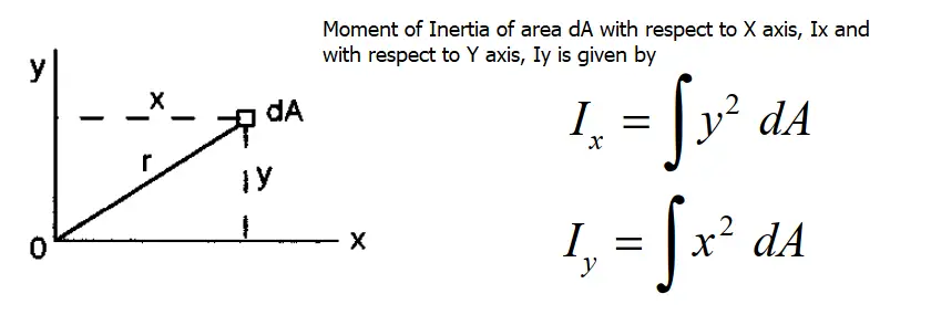
The moment of Inertia of an Area (I) represents the distribution of points in a cross-sectional area with respect to an axis. It is also known as the second moment of area. For an elemental area dA in the XY plane, the area moment of inertia is mathematically defined as Ix and Iy as shown in Fig. 1 below.
Fig. 1: Moment of Inertia with respect to X and Y axis
The Formula for Moment of Inertia
In beam theory, the formula of the moment of inertia is very important. Depending on the cross-section of the object the equation of the moment of inertia varies. Note that, the moment of inertia is always positive. In this section, we will find out the moment of inertia formula for a few common geometrical cross sections.
Moment of Inertia Formula for Square Cross-Section:
The moment of inertia equation for a square is given by Ix=Iy= a4/12 where a=length of side.
The Equation for Moment of Inertia for Circular Cross Section:
The moment of inertia for a circular cross-section is given by I=πd4/64 where d=Diameter of the circle. In a similar way, the moment of area of a pipe is given by I=π(D4-d4)/64 Where D=Pipe OD and d=Pipe ID.
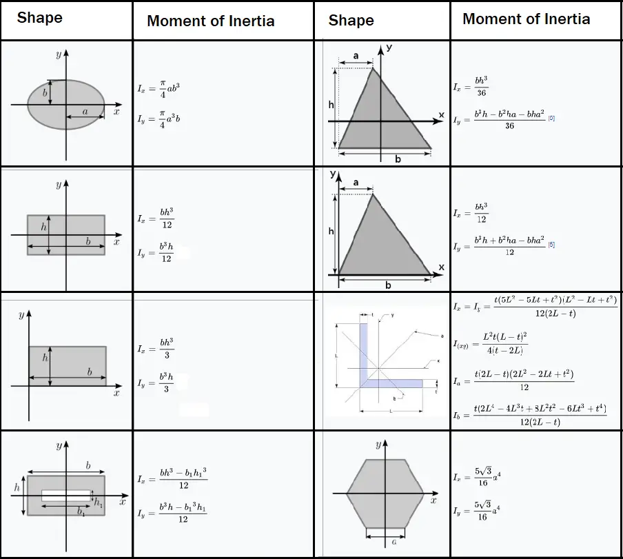
The following image provides the area moment of inertia formula for some more common shapes.
Fig. 2: Moment of Inertia of Common Geometrical Shapes
Units of Moment of Inertia
The unit of mass moment of inertia in the SI unit system is kg.m2 and in the FPS unit system is lbf·ft·s2
The unit of an area moment of inertia in the SI unit is m4 and in the FPS unit system is inches4.
Polar Moment of Inertia
The polar moment of inertia is defined with respect to an axis perpendicular to the area considered. It provides a beam’s ability to resist torsion or twisting. The polar moment of inertia (J) of a circular area is given by J=πd4/32.
Applications of Moment of Inertia
Mass moment of inertia provides a measure of an object’s resistance to change in the rotation direction.
Area moment of inertia is the property of a geometrical shape that helps in the calculation of stresses, bending, and deflection in beams.
A polar moment of inertia is required in the calculation of shear stresses subject to twisting or torque.
The moment of inertia “I” is a very important term in the calculation of Critical load in Euler’s buckling equation. The Critical Axial load, Pcr is given as Pcr=π2EI/L2.
A moment of inertia is required to calculate the Section Modulus of any cross-section which is further required for calculating the bending stress of a beam. Bending stresses are inversely proportional to the Moment of Inertia. The larger the moment of inertia, the greater is the moment of resistance against bending.
Section Modulus
The section modulus of a section is defined as the ratio of the moment of inertia (I) to the distance (y) of extreme fiber from the neutral axis in that section. Section modulus is denoted by “Z” and mathematically expressed as
Z=I/y
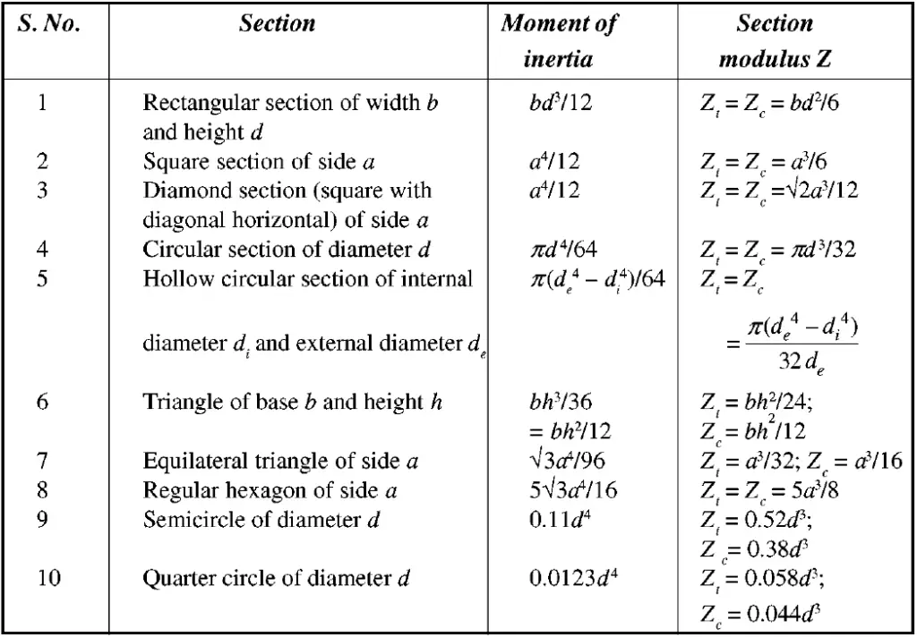
In SI unit systems the unit of Section Modulus is m3 and in the US unit system inches3. The table provided in Fig. 3 provides the moment of inertia and section modulus formula for common geometrical shapes. (Here, Zc and Zt are the section moduli in compression and tension)
Fig. 3: Moment of Inertia and Section Modulus Equations
Deluge System: Definition, Working, Applications, and Advantages
A deluge system is a fixed fire protection system designed to protect against severe fuel hazards. A large number of sprinklers simultaneously act to bring any undesirable fire event under control. Consisting of unpressurized dry piping and open sprinkler heads, the deluge system is directly connected to a water supply and upon activation, a deluge valve releases the water to all the open sprinkler heads simultaneously. Deluge systems can also release other fire-suppressing materials like dry powder, foam, chemicals, or inert gases. Until the deluge valve is activated by an electric, pneumatic, hydraulic, or manual release system, the system piping remains empty and dry but when activated, the deluge system floods the area through pressurized water or other fire extinguishing material.
The main purposes behind using deluge systems are any one or combination of the following :
Extinguishment of fire
Control of burning
Exposure protection
Prevention of fire
Working of a Deluge System
As deluge systems are used in special hazard installations, they must work quickly to protect the entire area. Fig. 1 shows a typical deluge system. A deluge system comprises of three main components: deluge spray nozzles and lines, deluge valve set, and deluge system water supply. The working of a deluge system consists of the following four steps:
A fire detection (Smoke/Heat/Ultraviolet/Infrared/Optical flame Detector) system detects the fire and sends the signal to the fire alarm panel to activate the deluge valve.
Immediately the deluge valve opens which is connected to a water supply.
Water flows into the piping system and starts discharging from all nozzles and open sprinklers.
After use, the deluge valve can be easily reset to normal operating conditions by draining the water remaining inside the pipe and valve body.
Fig. 1: Typical Deluge System
Types of Deluge Systems
According to the method of release, Deluge systems are classified into three categories:
Pneumatic release deluge system
Hydraulic release deluge system
Electrical release deluge system
Applications of a Deluge System
Deluge systems are used in special hazard installations requiring a large quantity of water to control a fast-developing fire. They provide high-velocity suppression. Typical applications of deluge systems are found in:
Flammable liquid handling systems.
Flammable liquid storage, and chemical storage areas.
Hydrocarbon processing plants.
Refineries/ Fuel Processing Plants.
Oil extraction plants.
Separation, distillation plants.
Large aircraft hangars.
Transformers.
Crude tanks and vessels.
Power Plants.
Data Storage units.
Paint Shops.
Theatres.
Codes and Standards for a Deluge System
The governing codes and standards for a deluge system design and manufacturing are
NFPA 15: Standard for Water Spray Fixed Systems for Fire Protection
API RP 2030: Application of Fixed Water Spray Systems for Fire Protection in the Petroleum and Petrochemical Industries.
ISO 6182: Fire Protection-Automatic Sprinkler System
NFPA 13: Standard for the Installation of Sprinkler Systems
IP MODEL CODE P19, By Energy Institute – Fire Precautions at Petroleum Refineries and Bulk Storage Installations.
Piping Requirements for Deluge System Design
As per NFPA, Requirements for piping arrangements are
Sch 40, Carbon Steel (Galvanized) Pipe for up to 8” sizes and
Sch 30, Carbon Steel (Galvanized) Pipe for 8” & above
Requirements for Piping Installation:
In the dry section of the pipe, a Suitable slope needs to be provided.
A low-point drain at a suitable location is required.
Pipe Velocity criteria for deluge system: NFPA 15 allows up to 7.94 m/sec of water velocity for the deluge downstream side. However, based on the project piping design philosophy velocity may be limited to 5 m/sec downstream of the deluge valve and 3 m/sec upstream.
The deluge system should be designed in such a way that within 30 secs of activation, the water spray fully covers the equipment in that region.
As per NFPA 15, the minimum Pipe Size for Deluge Systems is 1”.
Advantages of Deluge System
The major advantages of using deluge fire protection systems over other kinds of systems are:
They can easily control rapidly spreading fire.
Very quick response as all sprinklers are open.
Their operation can be made fully automatic.
Deluge system being a dry system, no risk of frozen pipes
They can also be used in conjunction with foam concentrate for better controlling certain types of fire.
Water disperses over a large area for efficient fire extinguishing.
Duplex Stainless Steel (DSS): Definition, Grades, Composition, Properties, and Applications
Duplex Stainless Steel is a specific group of engineering stainless steel materials consisting of the austenitic and ferritic phases in roughly equal proportions in the microstructure. They are widely popular because of their good corrosion resistance, high strength, and ease of fabrication. They are also popular by their acronym DSS. Compared to traditional austenitic stainless steel and ferritic stainless steel grades; Duplex Stainless Steels provide a range of benefits:
Improved Strength: Roughly two times stronger than normal stainless steel grades.
High Toughness and Ductility
High Corrosion Resistance
Cost-Effectiveness: High strength of DSS material required less pipe thickness reducing pipe weight. Also, lower levels of nickel reduce cost.
Applications of Duplex Stainless Steel
Excellent corrosion resistance with increased strength and affordable pricing makes duplex stainless steel (DSS) a popular choice for a variety of industries. Their wide uses are found in:
Chemical and liquid processing
Offshore (flowlines, risers) and other industrial operations
Duplex stainless steels have a higher chromium content, 20–28%; higher molybdenum, up to 5%; lower nickel, up to 9%, and 0.05–0.50% nitrogen as compared to austenitic stainless steels. For resistance against pitting corrosion, DSS material is an ideal selection. The resistance against pitting corrosion is characterized by the pitting resistance equivalence number, or PREN Number defined as follows:
PREN = %Cr + 3.3 %Mo + 16 %N
Depending on the PREN Number values, Duplex Stainless Steel is categorized into four grades.
Lean duplex grades (PREN range: 22–27): No deliberate Molybdenum addition. mainly used in the building and construction industry for bridges, pressure vessels, or tie bars. Example: S32001, S32101, S32304, S32202.
Standard duplex (PREN range: 28–38): The most widely used (More than 80%) duplex stainless steel material with mid-range properties. Example: S32003, S31803, S32205
Super duplex (PREN range: 38-45): Higher contents of Cr, Ni, Mo, N, and even W. Specifically designed for highly corrosive oil & gas and chemical industries. Example, S32750, S32760, S32950, S32808.
Hyper duplex (PREN >45): These are highly alloyed duplex stainless steel. Example S32707, S33207
Naming Convention for Duplex Stainless Steels
Various naming conventions are followed for duplex stainless steels such as:
Composition-based Names: For DSS 2205 or 2305; 22 or 23 denotes %Cr and 5 denotes %Ni in that specific DSS material.
AISI Designation: Only one DSS material type 329 has an AISI designation.
Duplex Stainless Steel Properties
As informed earlier the duplex name has arrived from the co-existence of both austenitic (FCC Structure) and ferritic (BCC Structure) in approximately equal proportions (Fig. 1). The major alloying elements are Chromium, Silicon, Molybdenum, Carbon, Nickel, Nitrogen, Manganese, Copper, Tungsten.
Fig. 1: Duplex Stainless Steel Microstructure
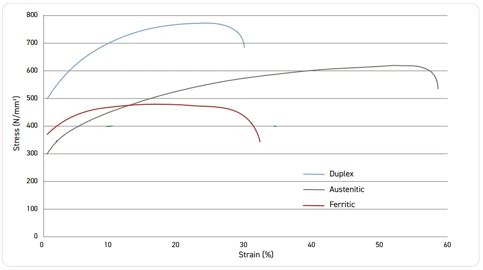
Typical duplex stainless steel exhibits a higher strength value as compared to stainless steel. But, the working temperature range of DSS is normally narrow as at around 300oC undesirable intermetallic phases (α’ -alpha prime phase) start to precipitate which decreases the mechanical properties and corrosion resistance by embrittlement phenomenon. The following table provides some selected properties of common duplex stainless steel grades.
The stress-strain curve of austenitic, ferritic, and duplex stainless steels are plotted in the following curve for reference:
Fig. 2: Stress-Strain curve comparison for SS and DSS
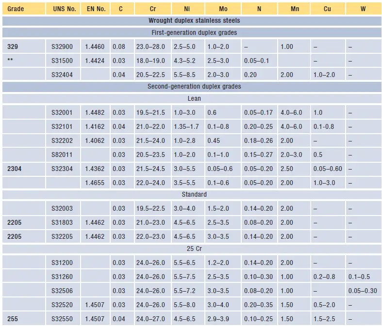
Composition of Duplex Stainless Steel
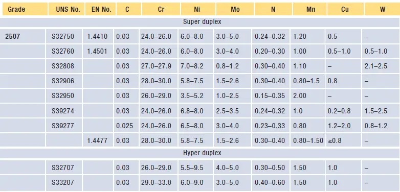
The following table in Fig. 3 and Fig. 4 provides the chemical compositions in %wt for common DSS and SDSS materials.
Fig. 3: Typical Chemical Composition of Duplex Stainless Steel
Fig. 4: Typical Chemical Composition of Super and Hyper Duplex Stainless Steel
Corrosion Resistance of Duplex Stainless Steel
Due to the presence of a relatively high % of chromium, molybdenum, and nitrogen, Duplex Stainless Steels exhibit a high level of corrosion resistance capability in a variety of environments. DSS materials are specifically selected for oxidizing, acidic, and hot alkaline environments. To fight against pitting corrosion, DSS is the ideal material choice. The PREN Number defined above describes the resistance of DSS against localized pitting corrosion. An increase in PREN Number increases the resistance against pitting corrosion that is quantified using Critical Pitting Temperature. Materials with higher CPT are more resistant to pitting corrosion. Duplex stainless steels possess better Stress Corrosion Cracking resistance than austenitic stainless steel.
Fabrication of Duplex Stainless Steel
Duplex Stainless steel is supplied in a pipe, plate, sheet, tube, fittings, or bar form. Depending on the requirement they must be fabricated. Special tools are required for the fabrication of duplex stainless steel materials. They have very good weldability and hot-forming capability. However, DSS materials are normally difficult for machining purposes.
Duplex Stainless Steel (DSS) and Super Duplex Stainless Steel (SDSS) are both types of stainless steel that combine the properties of austenitic and ferritic stainless steel. However, the key differences between them are:
Composition: SDSS has higher chromium (25-27%), molybdenum (3-5%), and nitrogen content compared to DSS, which typically has 22-25% chromium, 3-4% molybdenum, and lower nitrogen content.
Strength: SDSS offers higher yield strength than DSS, making it suitable for more demanding applications.
Corrosion Resistance: SDSS has superior resistance to pitting, crevice corrosion, and stress corrosion cracking, particularly in aggressive environments like seawater, sour gas, and chloride-rich conditions.
Applications: SDSS is often used in more extreme environments, such as subsea equipment and high-pressure pipelines, where the material’s superior performance is critical.
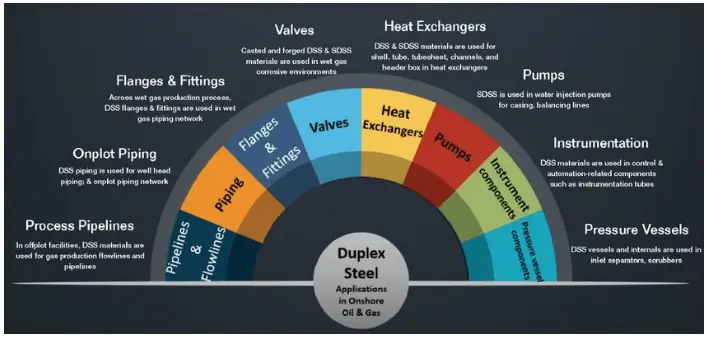
Fig. 5 below provides a nice image showing some of the applications of DSS and SDSS material in Onshore Oil & Gas:
Fig. 5: Applications of DSS & SDSS in Onshore Oil & Gas
Relationship between SDSS and DSS
SDSS (Super Duplex Stainless Steel) is an enhanced version of DSS (Duplex Stainless Steel). While both materials share a similar duplex microstructure (a roughly equal mix of austenite and ferrite phases), SDSS is designed for even higher performance. The relationship is that SDSS builds on the foundation of DSS by offering increased strength and better corrosion resistance, making it suitable for more demanding environments. Essentially, SDSS is a more advanced form of DSS with higher alloy content and improved properties.
Differences between SS and DSS
Stainless Steel (SS) and Duplex Stainless Steel (DSS) differ primarily in their microstructure, composition, and performance:
Microstructure: SS can be austenitic, ferritic, or martensitic, while DSS has a mixed microstructure of approximately 50% austenite and 50% ferrite.
Corrosion Resistance: DSS generally offers better resistance to pitting, crevice corrosion, and stress corrosion cracking, particularly in chloride-containing environments, compared to SS.
Strength: DSS has nearly twice the yield strength of austenitic SS, allowing for thinner sections and potential cost savings in certain applications.
Applications: SS is widely used in a variety of applications, while DSS is favored in more demanding environments, such as offshore platforms, subsea pipelines, and chemical processing plants.
DSS Pipe Material Specification
The DSS Pipe Material Specification defines the chemical composition, mechanical properties, and acceptable testing methods for Duplex Stainless Steel piping. A common specification is ASTM A790/A790M, which covers seamless and welded duplex stainless steel pipes for high-temperature and general corrosive service. The specification outlines requirements such as:
Chemical Composition: Specific ranges for elements like chromium, nickel, molybdenum, and nitrogen.
Mechanical Properties: Minimum yield strength, tensile strength, and elongation requirements.
Testing Methods: Includes hydrostatic testing, nondestructive testing (NDT), and intergranular corrosion testing.
Frequently Asked Questions of DSS with Answers
What is meant by duplex stainless steel?
The word duplex in stainless steel refers to the two-phase microstructure of DSS material. Duplex stainless steel is a family of stainless steel having ferritic and austenitic phase microstructure in approximately equal proportions.
Is 304 stainless steel a Duplex?
No, 304 stainless steel is austenitic stainless steel. It is not a duplex.
Is 316 stainless steel a Duplex?
Stainless steel 316 is not a duplex SS. 316 SS is austenitic in nature.
What is the purpose of duplex stainless steel?
Duplex stainless steels have roughly twice the strength of austenitic stainless steels and higher resistance to pitting corrosion, crevice corrosion, and stress corrosion cracking.
Does duplex stainless steel rust?
Duplex Stainless steel has a very high chromium content that prevents the DSS material from rusting. So, in general, duplex stainless steel does not rust. However, under a suitable corrosive environment, DSS may corrode or rust.
Is 2205 duplex stainless steel magnetic?
As duplex stainless steels are ferritic as well as austenitic, it does have magnetic properties. 2205 super duplex is also magnetic. All DSS materials are magnetic.
Does duplex 2205 rust?
2205 stainless steel being a DSS usually does not rust. But when exposed to severe conditions, it may corrode.
What is the difference between a duplex and a super duplex stainless steel?
Super duplex stainless steel is an improved duplex stainless steel. It possesses additional characteristics as compared to DSS. DSS has 25% chromium, 7% nickel, and 4% molybdenum content which makes the material have higher corrosion resistance and . strength than duplex stainless steel.
How strong is duplex stainless steel?
Duplex stainless has more strength as compared to other groups of stainless steel. Roughly, duplex stainless steel is around twice as strong as either ferritic or austenitic stainless steel.
Who invented the super Duplex?
Super Duplex stainless steel was developed by Langley Alloys in the mid-1960s and was launched in 1969.
What grade is a super duplex?
DSS grades UNS S32760, S32750, F55, 1.4501, etc are super duplex.
What is the DSS Material Code?
The material code for Duplex Stainless Steel (DSS) typically refers to a standardized designation used in engineering and procurement to specify the type of material. One common code system is the Unified Numbering System (UNS), where DSS is often designated by codes such as:
UNS S31803: Standard grade of DSS, also known as 2205.
UNS S32205: An improved version of S31803 with slightly higher nitrogen content, offering enhanced corrosion resistance.
Which is cheaper: DSS or SDSS?
Duplex Stainless Steel (DSS) is generally cheaper than Super Duplex Stainless Steel (SDSS). The lower cost of DSS is primarily due to its lower alloy content, particularly the reduced levels of chromium, molybdenum, and nickel compared to SDSS. While SDSS offers superior strength and corrosion resistance, its higher material cost reflects these enhanced properties. However, the choice between DSS and SDSS should be based on the specific application requirements, as SDSS may provide cost savings in the long term by reducing maintenance and extending service life in harsh environments.
The guided Cantilever method is one of the approximate methods for piping flexibility checking. This method is widely used by piping designers to check the approximate flexibility of simple piping configurations. A Guided cantilever is a beam whose one end is fixed and the other end is held parallel to its original position. The image shown in Fig. 1 represents a Regular and Guided Cantilever beam.
Fig. 1: Guided Cantilever Beam Example
Application of Guided Cantilever Method
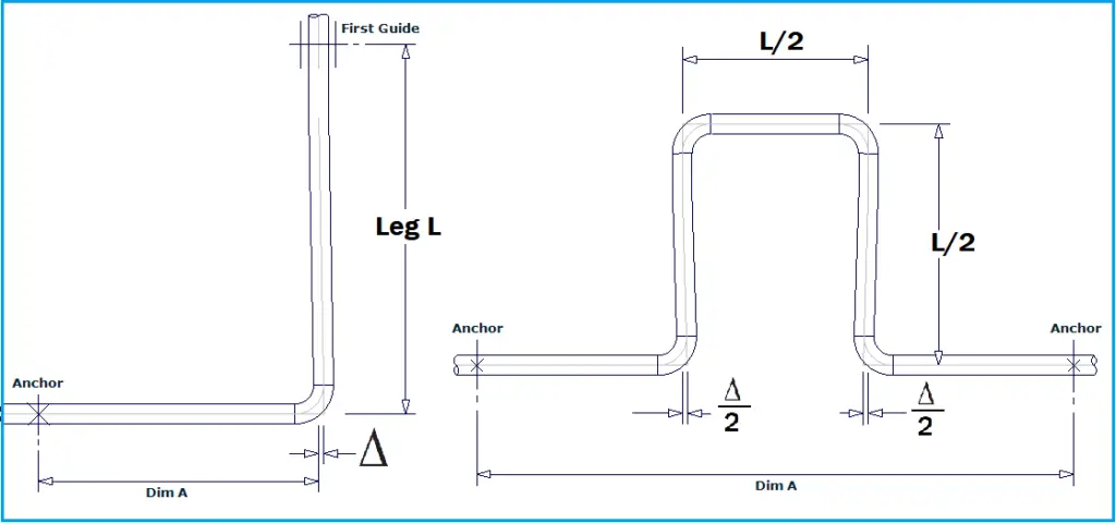
The guided cantilever beam shown in Fig. 1 is basically half of the fixed beam subject to a concentrated load. To calculate approximate forces and moments in a given length of the pipe due to thermal expansion, these beam models are often used. However, the major application of the guided cantilever method is to calculate the leg length (absorbing leg) required for a given thermal displacement. The distance of the first guide after a long straight turn or the expansion loop length in between two fixed anchors can be approximately calculated using the guided cantilever method. Refer to Fig. 2 below.
Fig. 2: Absorbing Leg Length using Guided Cantilever Method
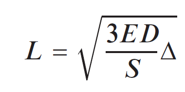
Using the guided cantilever method, the absorbing leg L, perpendicular to Dimension A (Fig. 2) can be calculated using the following Formula:
For Carbon steel, the above equation can be approximated as L=66 (D∆)1/2
Assumptions in Guided Cantilever Method
The assumptions behind the guided cantilever method can be listed as follows:
The piping system has only two terminal points which are composed of a straight leg of a pipe with uniform thickness and size and the square corner intersection,
The thermal expansion is absorbed only by a leg in the perpendicular direction
All piping legs are parallel to coordinate axes.
The amount of thermal expansion a given length can absorb is inversely proportional to its stiffness.
The legs act as guided cantilevers subjected to bending under end displacements and the rotation of the end is not permitted.
Limitations of the Guided Cantilever Method
The guided cantilever method is limited to simple geometries only; For complex configurations, it can not be applied.