Autopipe is a computer-based engineering program to determine pipe stresses, pipe support design, flange analysis, and equipment nozzle load analysis under dynamic and static load conditions. Autopipe incorporates piping codes such as ASME, British standard, European, NEMA, ASCE, API, and WRC guidelines that are useful in providing a comprehensive analysis of a piping system in addition to 30 piping codes. Autopipe has three editions namely Standard, Nuclear and Advanced. The advanced version provides advanced analysis which is not available in the standard version of Autopipe. Whereas on the other hand, the nuclear version includes all the advanced features, JSME PPC thermal and nuclear transient analysis, and nuclear ASME in classes 1, 2, and 3. Autopipe is well-established software commercially available since 1986. The owner of Autopipe software is Bentley.
What is Caesar II?
Caesar II introduced in 1984 by Intergraph Corporation is the most widely used software for pipe stress analysis. Caesar II allows accurate and quick analysis of piping systems that are subjected to thermal, weight, pressure, seismic, and wind. Caesar II can be used to analyze piping systems of any complexity or any pipe size. It is licensed by almost all the engineering firms of the world. Currently, the software is owned by Hexagon.
AutoPipe vs Caesar II
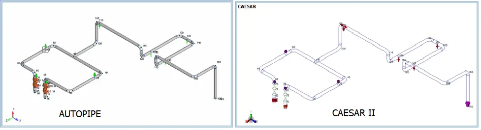
To find out the differences between AUTOPIPE and CAESAR II we will consider a sample model and study the features of both software. The model shown in Fig. 1 is a pump system where Pump A is Point 1 or Pump B is Point 90 and both Pump A and B are in the operation. Here point 170 is connected to a vessel that is oriented in the Z-axis and at the same point we have entered a flexible anchor defined by CAESAR under the option that shows WRC297 and by AUTOPIPE we have under the option that shows user flexibility.
Fig. 1: Pump Model in Autopipe and Caesar II
Preparing Load Cases
Both CAESAR and AUTOPIPE perform the same task by providing the user with the stress analysis results based on the load cases that are applied to a geometric model of a particular piping system. However, there is little fundamental difference between both applications on how to load combinations are combined.
One of the fundamental differences between CAESAR and AutoPIPE is the load sequence versus load vector superposition.
Consider the following example:
L1 W+P1+T1 (OPE) is equivalent to AutoPIPE load case as GRT1P1
L2 W+P1 (SUS) is equivalent to AutoPIPE load case as GR+Max P
L3 L1-L2 (EXP) is equivalent to the AutoPIPE T1 case
AutoPIPE load sequence approach does not require intermediate equations like L3 that is found in CAESAR II. This reduces the complexity of load combinations and the length of the output report. Also, AutoPIPE has more advanced non-linear analysis with load sequencing (without iteration problem) and therefore the users can expect more accurate non-linear results than other programs.
In Caesar II, there is an additional Hanger load Case variable H for using Spring hangers but Autopipe automatically takes care of the same in the calculation.
Changing Global Parameters
Global changes to various parameters like pressures, temperatures, materials, etc can be done in both applications. But there are a few differences between both of them as shown below:
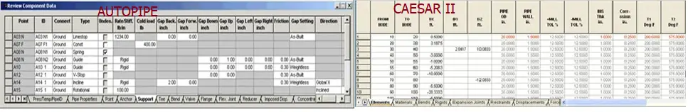
In Caesar II, there is no multiple copy/paste and column sort option. One can modify one cell at a time.
Autopipe is bi-directionally synchronized with the plot, It can make global changes across multiple cells of like data. It can sort any column into logical data groups. Autopipe selects multiple ranges of components with graphical highlights. It has real-time graphical plot updates with multi-level undo and redo. It has customized printing. It behaves like Microsoft Excel, unlike Caesar Like spreadsheet.
Fig. 2: Changing Global parameters in Autopipe vs Caesar II
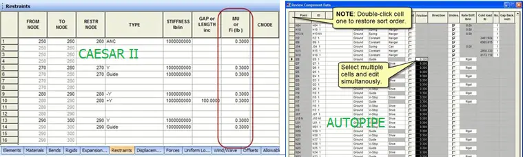
In Caesar, we have to change friction values one by one or can be replaced by find and replace values similar to excel.
In Autopipe, in the support grid, one can double-click click column heading in order to save the data. One can select multiple cells to make changes or can select one complete column and then select one cell by holding the CTRL key. Then we can enter a new value in the first cell and press CTRL+Enter
Fig. 3: Changing Support Friction in Autopipe vs Caesar II
Changing Process Parameters in the Model
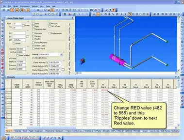
Caesar II uses a list spreadsheet as shown in Fig. 4
Fig. 4: Changing Process Parameters in Caesar II
Autopipe makes global changes to parameters like pressure and temperature.
Other Differences between Autopipe & Caesar II
Other differences between Caesar II and Autopipe are tabulated below:
AutoPIPE
Caesar II
AutoPIPE uses an Alpha-numeric node numbering system.
Caesar II uses only a numeric node numbering system.
In Autopipe, up to 99 levels of Undo and Redo option is available.
In Caesar II, undo and redo option is lost once the input module is exited.
AutoPipe allows users to input up to 100 sets of pressure and temperatures. So for complex systems, one can prepare as many load cases as he wants in a single file.
Caesar II allows only 9 sets of temperature and pressure inputs. So for complex systems where many temperature cases are required one needs to prepare two or more caesar files to simulate all operating load cases.
In Autopipe, within a single interface, all editions of codes are available and one can easily access any code edition with ease.
For Caesar II, the user has to purchase different software versions to work on different code editions.
Autopipe allows users to open more than one Autopipe window with the same license on the same PC.
Caesar II allows only one Caesar II working window.
Autopipe does not allow users to modify friction stiffness value to alter the results.
In Caesar II, modification of friction stiffness value is possible in the configuration setting.
AutoPIPE considers rigid bodies to be 100 times stiffer than the connecting pipe material.
CAESAR II multiplies the pipe wall thickness by 10 to make it rigid, keeping the pipe inside diameter, and the weight of the element unchanged.
PMP® Certification is a Project Management Professional Certification issued by Project Management Institute. There is no doubt that PMP is one of the most valued Certifications in the entire world of Project Management. PMP-certified managers have a certain level of prestige and greater access to jobs with higher salaries. Research conducted on several firms has discovered that companies with PMP-certified project managers are more competitive, productive, and meet their goals within the scheduled time. Several salary survey reveals that “PMP certification holders draw 20-25 percent more salary than their non-certified counterparts”
How do I get inspired for PMP Certification?
When I decided to improve my skills I searched on the Internet and LinkedIn to get the relevant course. After weeks of searching, I came to know about PMP certification. Then I started a deep search about the Project Management and Project Manager’s increments in roles, Salaries, and the respect they get after having the 3 Letters (PMP) behind their names.
I was surprised to know that only 1 Million active PMP Certified Professionals are available in the entire world over the span of 4 decades. I was super shocked to know that only 40,000 and 150,000 active PMPs in India and China respectively. The ratio is 0.006 % which is an almost negligible number (190,000/2.8 Billion). For your Understanding – If you go for an Interview that has 100,000 Competitors from India and China, there is a possibility of having 7 PMPs appearing for the interview. Sounds Great… Right! This is the real scenario by the way. Continue reading this article in which I will share my success story in achieving the PMP global credentials. It looks like so many activities but it is simple indeed.
See the below Image (Fig. 1), It was the daily update of the newsfeed on my LinkedIn from September to December 2020. Several Engineers, Managers utilized the COVID-19 situation to prepare for the PMP Exam and successfully clear it.
I was inspired and motivated by the success of others and also I don’t want to be the guy who is standing in the middle of the below Image. I believe you will not be the one after reading this article. I’m not going to say the same as what all the articles about the PMP explain.
Fig. 1: LinkedIn newsfeed on PMP certification
Stepwise action plan for PMP Certification
Below are the step-by-step actions you have to plan and follow to fulfilling your dream to be PMP certified.
Believe in yourself that you will be PMP after passing the Exam. Explain this to your family members as well. Without their support, it is almost impossible to spend time on preparation. Dedication is the most important investment for this exam.
When you start preparing turn off your expert mode and change to learner mode. In other words, you should not compare what you learn with what you have experienced before. The examination will be from the PMI Point of View only. You should unlearn your experience to understand the concept as per the PMBOK (Project Management Body Of Knowledge) guide.
Find a mentor who is ready to understand and support you by providing mock test questions, explanations, and doubt-clearing sessions. I was lucky to have a mentor with 100 % dedication. He played a major role in my success.
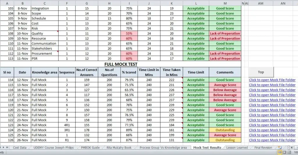
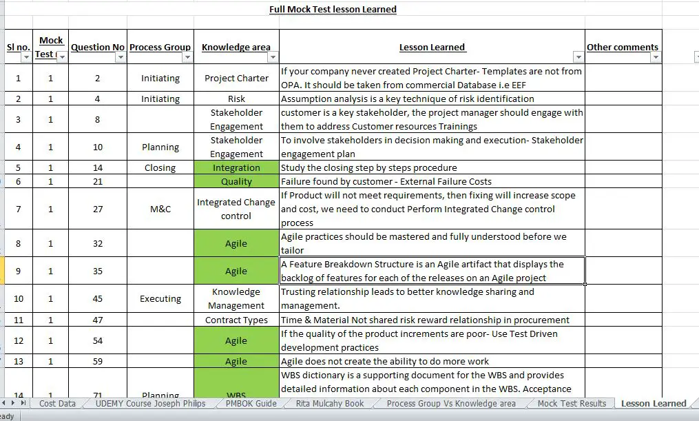
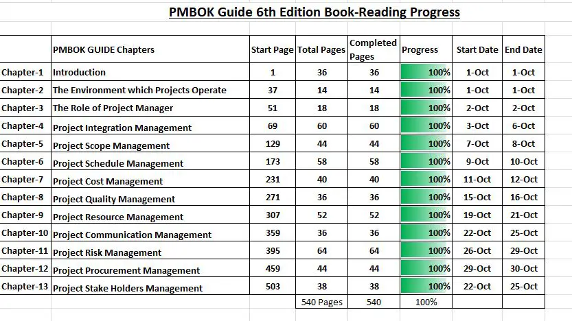
Prepare an MS Excel Spreadsheet consisting of below
Study plan with Start and Finish Dates
Mock Test score
Weak Knowledge Area
Expenses for the Course including exam Fees.
Purchase PMBOK Guide Hard Copy to study comfortably. Many persons suggested using Rita Mulcahy’s book as a guide for people having difficulty in reading PMBOK. Don’t go for more than 2 books to avoid misunderstanding.
Check Youtube Videos from PMPwithRay which are very useful for understanding ITTOs (Inputs, Tools & Techniques, Outputs of Processes on all the 10 Knowledge areas). No need to memorize ITTOs, very few or no questions will directly ask about the ITTO’s.
Try purchasing the membership together with the exam schedule. I suggest following to book the exam date as per the below steps.
Gain 35 Hours of Education
Submit the Exam application (Will be approved within 5 working days)
Attend at least 8-10 Full Mock tests (Free Mocks Available Online)
Analyze the results of the mock tests by categorizing the wrong answers by knowledge area. Carry out the 80/20Pareto principle (i.e) 80% of your mistake will come from 20% of the knowledge area. If you are able to learn those topics with mock scores of about 75-80 % you are on the safer side.
Once you gain confidence after attending the mocks, pay for the 1-year membership on PMI Website together with the exam fee (You will get a discount if you have a membership)
You can fix the exam date and you can write the exam Online from home or through the Pearson Vue Test Center.
Experience on Exam Day:
The PMP exam is really a difficult exam I ever attended. The exam will have 2 sessions with a break in between.
PMP certification is designed by project professionals, for project professionals and validates that you are among the best—highly skilled in three major topics PEOPLE, PROCESS, and BUSINESS ENVIRONMENT. So, You cannot ignore some topics during preparation. To Pass the Exam You have to score more than Target on all three Topics.
You have to be clear on 3 approaches AGILE, WATERFALL & HYBRID. It is to validate that you have the project leadership skills employers seek. So, you will prove yourself.
The most common problem during the exam is there will be 2-3 choices that look like the right answer in the multiple-choice questions. The only solution is to have a lot of practice. (I answered 5800 Questions during preparation through mock tests)
The next common problem during the exam is time management. I have heard many people told that they cannot answer all the questions so they failed the exam. I have a very good solution for this. From the beginning of mock tests consider 1 minute for 1 question, so you will finish the exam in 3 hrs’ time. Use the remaining time to review the answers. Hope this will help.
If you feel you are not sure, mark the question for review and check later. Don’t read the question more than 2 times in the final exam.
That’s it!! It May look difficult but not impossible, you are reading this so you have the hunger to earn PMP certification. You are doing the right thing which many are not even thinking about.
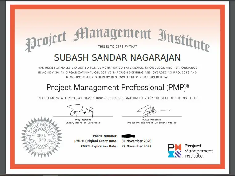
I’m glad to share screenshots of the excel file and PMP Certificate for motivating the PMP Aspirants.
My LinkedIn Profile views were at their peak when I posted that I have passed PMP Exam. I thanked all my family members, my Mentor, and all the people who supported and guided me to get these global credentials.
I passed on Nov 30,2020 and made post on Dec 01,2020.
Finally, I would like to share the words of Mr. Joseph Phillips ” KEEP MOVING FORWARD”, “I BELIEVE YOU CAN DO THIS”.
Please post when you pass the exam after checking these articles.
I want to share a copy of the MS Excel file I prepared for my self-assessment. Who want to have the Full PDF file or Draft of the Original XLS Format, drop me an Email: subashmech2011@gmail.com.
Frequently asked questions about PMP Certification
1. Is PMP better than MBA?
Undoubtedly yes! Because MBA is mostly study-oriented whereas PMP is mostly experience-oriented. That’s why PMP Aspirants should have a minimum of 3 years of Work Experience.
2. If an engineer is not working in the project department, can he attain PMP certification?
Yes. Any Engineering Graduate with 3 years of Experience is eligible to get the PMP Global credentials. Whether you are from IT or from Non-IT (like Construction, Finance, Banking, FMCG, Engineering, or Real Estate) PMP knowledge can be applied. Whenever there are new projects then Project Management will come into play. So earning a PMP is always an added advantage and will enhance your skills.
3. I’m not an engineer, I want to earn PMP. Can I go for it?
Of course Yes. You can go for it. Qualification is to have a high school diploma or an associate’s degree (or global equivalent) with 5 Years of Experience or get a CAPM certification from PMI.
4. I saw advertising from some learning centers that mentioned “You get the PMP Certification within a week”. “You earn PMP without appearing for the exam” Is it possible?
These are the keywords used by frauds, and spammers who are looking for cheating people who want to cheat in the exam. If you come across this kind of advertisement, please don’t believe them, you will lose your money and hope to pass the exam. No Pain, No gain!
What is Front End Engineering Design or FEED Engineering? FEED vs Detailed Engineering
Front End Engineering Design or FEED is an engineering design approach adopted prior to detailed engineering, procurement, and construction. It is an important engineering design phase that is used to control project expenses and thoroughly plan a project before bid submission. Benchmark studies have shown that FEED constitutes roughly 2% of the project cost but properly executed FEED projects can reduce up to 30% of costs during design and execution. In this article we will discuss more about FEED project details with respect to oil and gas projects.
What is FEED?
Front-End Engineering Design (FEED) is a crucial phase in the project lifecycle of oil and gas developments. It bridges the gap between project conceptualization and detailed engineering design. FEED focuses on defining the project scope, establishing technical requirements, and providing cost and schedule estimates. It aims to ensure that the project is well-defined before significant capital is committed. FEED serves as the blueprint for project execution, laying down the framework that guides detailed engineering, procurement, and construction phases.
Front-end engineering design is a basic engineering phase conducted after conceptual design or feasibility study. FEED is also known as Front End Loading or Front End Engineering (FEE).
Applications of FEED
Front End Engineering Design has its uses across various industries. Here are the sectors that use FEED at different stages of their applications.
Oil & Gas
Construction
Automation
Manufacturing
Chemical processing
Process Industry
Production line design
EPC
Power Generation
Refining
EPCIC
Equipment design
Process system design
Machine Vision
Pharmaceuticals
Petrochemicals
Food & Beverages
Purpose of Front-End Engineering Design
The main purpose of FFED or Front End Engineering Design is
to define the technical and project-specific requirements for an understanding of the clear project scope.
to prepare the project approach and basis of design for the system.
to develop a good project cost estimate for budget authorization.
to reduce the risk of the project.
to estimate the project duration and schedule during the detailed design phase.
to identify potential risks early to enable the development of mitigation strategies to address them.
A number of preliminary engineering documents are produced in the front-end engineering design phase (Click here to learn about all 12 phases of project implementation) which are used as the start-up documents for the detailed engineering design phase. Combinedly, these documents are known as the “FEED Package”. A good FEED package reflects all of the client’s project-specific requirements to avoid significant changes during the execution phase. The FEED package forms the basis for the design execution of EPC or EPCM projects.
Time Duration for FEED Project
FEED projects are fast-track engineering projects. The time duration for a front-end engineering design project is normally less than one year. So, it requires enough experience to execute FEED projects with safety within a short time period. Close communication between Project Owners and Operators (Client) and the Engineering Consultant is required to address all the client requirements in the FEED package.
Types of FEED Project
Depending on the extent of the detailing required during front-end engineering design phases, FEED projects can be categorized into three groups
Basic FEED
Intermediate FEED and
Extended FEED
Front End Engineering Design Deliverables
Considering Piping Engineering as the basis, the front-end engineering design deliverables for a FEED project can be listed as follows:
The FEED phase offers several benefits, which significantly impact the overall success of oil and gas projects:
1. Enhanced Project Clarity
FEED provides a clear and detailed design blueprint, reducing ambiguity and setting well-defined project goals. This clarity helps in aligning all stakeholders and minimizing misunderstandings.
2. Improved Cost Control
By providing accurate cost estimates and identifying potential cost overruns early, FEED enables better financial planning and budget control. This reduces the likelihood of unexpected expenses during later stages.
3. Reduced Project Risk
Early identification and assessment of risks allow for the development of effective mitigation strategies. This proactive approach helps minimize delays and avoid costly setbacks.
4. Regulatory Compliance
FEED ensures that the project design adheres to regulatory requirements and industry standards. This compliance is crucial for securing permits and avoiding legal issues.
5. Optimized Project Schedule
A well-defined FEED phase contributes to a more accurate project schedule, helping to streamline the construction and commissioning phases. This reduces the risk of project delays and ensures timely completion.
Inputs required for FEED Project
Roughly the following inputs are required to proceed with a FEED project
FEED Engineering Scope of Work
Feasibility Study Report
Location and Details of the area where the plant will be built
List of Applicable Codes and Standards
Customers technical practices
Overall, the FEED phase is considered an important and critical planning tool.
What comes after front-end engineering design or FEED Engineering?
Front-End Engineering Design identifies all technical requirements, potential risks, and approximate costs of the proposed project. Once there is a green signal for the project execution, Detailed Design Engineering, Detailed Engineering, or DD Engineering comes into place. So, Detailed Engineering comes after FEED engineering.
What is a FEED study?
The Front-end engineering and design process is one of the most important pre-project planning activities. A typical FEED study consists of producing technical documents, confirming product specifications, clarifying the project scope, and estimating the approximate project cost.
What is pre-FEED engineering?
Pre-FEED Engineering is a preliminary step that is usually undertaken before starting the basic engineering work. Pre-FEED engineering is an optional project phase and may be skipped. In the pre-FEED stage, the technical and economic feasibility of the project is sometimes confirmed. Depending on the nature of the project and the uncertainties involved, pre-FEED work may be combined with conceptual work and studies.
What is the front end of a project?
The front-end phase of a project is the initial phase of a project when the project idea is conceived. The front-end phase of the project ends when the final decision to start or not start the project is made.
Differences between FEED and Detailed Engineering: FEED vs Detailed Engineering
Both FEED and detailed engineering are completely different terms in a project life cycle. FEED is the basic engineering with the aim of establishing the project costing. Whereas, detailed engineering is the actual detailed project work for design and construction. Some of the major differences between detailed engineering and FEED engineering are tabulated below:
FEED Engineering
Detailed Design Engineering
Front End Engineering Design is an up-front basic engineering phase. This is an early phase after conceptual design; which precedes Detailed Design.
Detailed Engineering is the design phase when all design work is done in detail to put into construction and operation. It follows FEED; comes after project approval and before construction.
FEED develops a comprehensive design basis and outline of the project.
Detailed Design finalizes all technical details required for construction and installation.
FEED is done mainly to assess the cost and produce preliminary basis documents. It provides a preliminary cost estimate and budget analysis.
Detailed Engineering is the design phase when all design work is done in detail to put into construction and operation. It offers more accurate and detailed cost estimates based on the finalized design.
FEED is done with an acceptable level of accuracy. It is a high-level design with preliminary specifications and layout.
Detailed engineering is done with utmost accuracy. It is a detailed design with precise calculations, materials, and dimensions.
The time requirement of FEED engineering is short.
Detailed Engineering requires more time as compared to FEED.
The cost and manpower requirement for the FEED project is less.
Detailed Design needs more manpower and the associated cost is also much higher than the FEED stage.
The FEED phase may not end with Detailed Engineering
All Detailed Engineering projects usually have a FEED phase.
FEED outlines a preliminary project schedule with major milestones.
DD develops a detailed construction schedule with specific tasks and deadlines.
The FEED phase identifies potential risks and develops preliminary mitigation strategies.
The DD phase refines risk assessments with more detailed analysis and updated mitigation plans.
FEED allows for design changes and refinements as the project scope is defined.
The detailed design phase focuses on finalizing and locking in design details with minimal changes.
During FEED, a FEED report is produced summarizing the design approach, cost, and schedule estimates.
Detailed design generates detailed engineering documents, including drawings, specifications, and calculations.
Table 1: Detailed Engineering vs FEED Engineering
Front-End Engineering Design (FEED) is a pivotal phase in the lifecycle of oil and gas projects, setting the stage for successful execution and project delivery. By providing a comprehensive design blueprint, cost estimates, and risk assessments, FEED ensures that projects are well-planned and positioned for success.
Maximum Shear Stress Theory: Tresca Theory of Failure
Maximum shear stress theory provides failure criteria for mechanical components made of ductile material. This failure criterion is developed by the French mechanical engineer, Henri Tresca, and based on his name maximum shear stress theory is also known as the Tresca theory of failure. Due to their enormous contribution to the field of plasticity, Henry Tresca is popular as the father of the field of plasticity.
Maximum shear stress theory is one of the two main failure criteria that are widely used in recent times for predicting the failure of ductile materials. To establish the failure criteria of material, all failure theories compare a specific parameter with the same parameter for the uniaxial tension test. The maximum shear stress theory is no exception and the parameter for comparison in Tresca theory is maximum shear stress.
“The maximum shear stress theory states that the failure or yielding of a ductile material will occur when the maximum shear stress of the material equals or exceeds the shear stress value at yield point in the uniaxial tensile test.”
Maximum shear stress theory formula
Let’s deduce the mathematical form of the above-mentioned Tresca theory statement. Considering principal stresses, at the yield point, the principal stresses in a uni-axial test, σ1 =σy; σ2 = 0 and σ3 = 0. So the maximum shear stress at yielding: σsy =σ1/2. Therefore σsy = σy/2
Now assuming σ1 >σ2 >σ3; the maximum shear stress for the material is given by:
τmax=(σ1 -σ3 )/2
Now comparing these to maximum shear stresses following Tresca theory, failure will happen when τmax>=σsy
Safe Design Condition as per Tresca’s theory of failure
So the design of a mechanical component should be based on the following maximum shear stress theory equation
τmax<=σsy or (σ1 -σ3)<=σy
The factor of safety (N) can also be calculated based on maximum shear stress theory and given by N=σsy /τmax
Hence, the maximum permissible shear stress for designing a component as per maximum shear stress theory is given by τmax =σsy /N
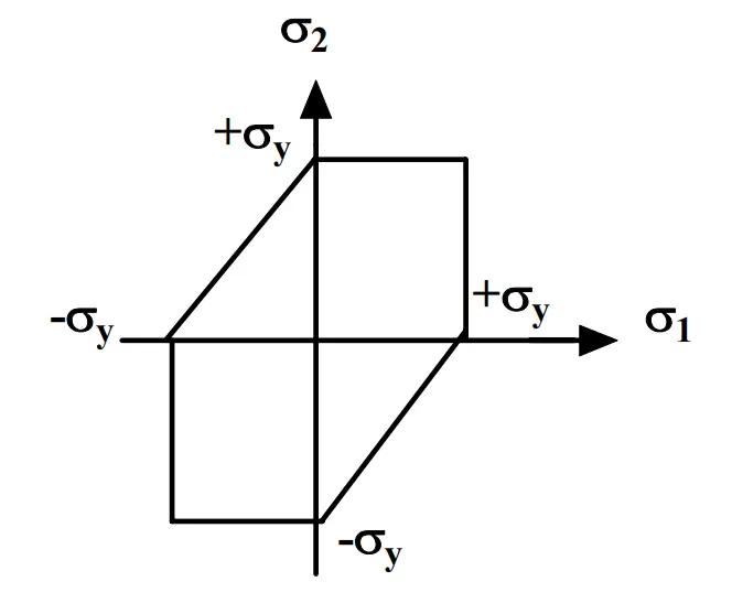
The failure envelope for Tresca’s theory of failure is provided in Fig. 1 below:
Fig. 1: Failure Envelope as per Maximum Shear Stress Theory
Steps for using the Maximum Shear Stress Theory
To use the maximum shear stress theory in problem-solving the following steps are necessary to be followed:
Step 1: Determine the three principal stresses (σ1,σ2, and σ3) from the tri-axial stress system using principal stress equations or Mohr’s circle method.
Step 2: Find out the maximum (σ1) and the minimum (σ3) principal stresses.
Step 3: Determine the value of the maximum shear stress τmax=(σ1 -σ3 )/2.
Step 4: Find out the allowable stress value of the material; allowable stress= σsy /N or σy /2N as mentioned above (N=Factor of safety)
Step 5: Compare the value calculated in step 3 with the allowable value found in step 4. If the Value at step 3 is less than the allowable value at step 4, then the design is safe as per the maximum shear stress theory.
Maximum Shear Stress Theory vs Von Mises Stress Theory
Von Mises and Tresca’s failure criteria are normally presented jointly with little discrimination between them. However, there are some differences between them which are tabulated below:
Maximum Shear Stress Theory
Von Mises Stress Theory
Maximum Shear Stress theory or Tresca theory of failure relates to the maximum shear stress of ductile materials.
Von Mises’s stress theory represents the maximum distortion energy of a ductile material.
This theory is considered to be more conservative.The Tresca theory, generally provides higher safety margins in certain applications.
Considered less conservative when compared with Tresca’s theory. It provides a more refined approach to determine yielding under complex loads.
Component cost designed based on Tresca theory increases.
Component Cost is Optimized for the design based on Von mises theory.
Required only two principal stress equations (σmax and σmin) to calculate the maximum shear stress.
Use all three principal stresses (σ1 ,σ2 , and σ3) in its equation for calculating Von Mises Stress.
Predicts yielding based on maximum shear stress differences.
Predicts yielding based on a combination of all principal stresses.
The failure envelope for Tresca theory and Von Mises theory is given in Fig. 2:
Fig. 2: Failure Envelope as per Tresca and Von Mises Stress Theory
Limitations of Maximum Shear Stress Theory
While the Maximum Shear Stress Theory provides a valuable framework for predicting material failure, it has its limitations. Some of the key limitations include:
Material Behavior: The theory is primarily applicable to ductile materials. For brittle materials, other criteria, such as the Mohr-Coulomb criterion, may be more appropriate.
Complex Loading Conditions: In cases where multi-axial loading is present, the Maximum Shear Stress Theory may not fully capture the material behavior.
Non-Isotropic Materials: The theory assumes isotropic material properties, meaning it may not apply to materials with directional dependence in their properties.
Temperature Effects: The theory does not account for changes in material properties due to temperature variations, which can significantly affect yield strength.
The maximum shear stress theory does not give accurate results for the state of pure shear stresses developed by the Torsion test.
The Tresca theory provides conservative results leading to an increase in component cost.
Applications of Maximum Shear Stress Theory
Structural Engineering
In structural engineering, the Maximum Shear Stress Theory is often applied to predict the failure of beams, columns, and other structural elements subjected to various loading conditions. By analyzing the shear stresses in components, engineers can ensure that structures remain safe under expected loads.
Mechanical Design
Mechanical components such as gears, shafts, and fittings often experience complex stress states. Using the Maximum Shear Stress Theory allows designers to assess the likelihood of failure in these components, leading to safer and more reliable designs.
Geotechnical Engineering
In geotechnical applications, the Maximum Shear Stress Theory can be used to analyze soil stability under various loading conditions. Understanding the shear strength of soil is crucial for designing foundations, retaining walls, and other earth structures.
Piping Engineering
In piping stress analysis, the Tresca theory is widely used.
In conclusion, the Maximum Shear Stress Theory remains a cornerstone of material failure analysis in engineering. Its ability to predict yielding under complex stress states is invaluable across various fields, from structural to mechanical engineering. Despite its limitations, it serves as a reliable criterion for assessing material behavior and designing safe structures and components.
What is a Topographic Survey? | Cost of Topographic Survey
A topographic survey identifies and measures the exact location, shapes, arrangements, and features of all-natural and manmade features on a specified land surface. It gathers data on land contours, the elevation of the terrain, etc required by engineers, architects, local government bodies, and contractors for accurate visualization for development/updation work. The topographic survey encompasses a broad range of surveying and mapping products, ranging from ground to aerial mapping and underground surveys.
Depending on the client’s requirement, a topographical survey picks up several different elements like
Man-made Structures and features
Buildings & structures
Boundaries and fence lines
Surfaces such as paving, tarmac, concrete, etc
Services such as power lines, telephone lines
Natural features
Drainage features such as inspection chambers
Street furniture like benches, bins, lamp posts, etc
Trees, bushes, and vegetation
Changes in surfaces
Ponds, lakes, watercourses
Ground heights/contours
Water levels
After the topographic survey, the collected information is compiled into an electronic CAD (Computer-Aided Design) file (AutoCAD, Microstation) to prepare a 2D plan drawing. Which can be printed as required. A topographic survey is also known as a contour survey.
Requirements of Topographic Survey
To correctly plan and execute any project with safety, a topographic survey provides accurate measurements explaining how the existing site is arranged. Hence, a Topographic survey is the starting point for the design and construction work of various projects like:
New buildings/structures/construction/architecture
Civil engineering projects like road design, bridge design, tunnel design, or improvements.
Land repurposing/environment restoration/land development
Utility design
Grading or drainage projects
Pipeline projects for pipe routing
The regulatory requirement for construction work
Re-positioning of boundaries
Geology, petroleum, and forestry
A topographic survey helps in preparing alignment drawings, preparing cross-sectional profiles, identifying existing structures, controlling locations, establishing elevation differences, and finding the presence of underground utilities like pipelines, electrical cables, etc.
Process of Topographic Survey
A topographic survey process consists of various steps like:
Receiving the client specification on the topographic survey that includes levels of survey details and information they are looking for.
Planning the time schedule with the client and negotiating the price.
Gathering Site data from the topographic survey.
Processing the data and preparing it as per the agreed format.
Quality assurance
Final handover of the report to the client.
Gathering survey data is the most important step. The time required for a topographic survey is dependent on
The size of the area to be surveyed and
The complexity of the terrain
The level or detail and accuracy required
Equipment /Tools for Topographic Survey
A topographic survey is conducted using various survey equipment and tools that measure distances and angles with extreme accuracy. Typical tools are
GPS survey equipment
Laser Scanning Tool to accurately record position points in plan and elevation.
Tripod-mounted robotic total station with appropriate software
A wide range of information can be produced from topographic surveys. This information is used for producing topographic survey drawings. Some of the outputs from the topographical survey are:
Drawings – Plan and elevation drawings, sectional drawings, and lighting plans
3D Point Clouds for producing 3D site models.
Photographs to get actual site information and feel
Schedules – Including chamber inverts and pipe/pipeline diameters.
A detailed topographical survey report mentioning major details.
Advantages of Topographic Survey
The main advantages of conducting a topographic survey are:
Reduction of risk from costly mistakes due to the absence of accurate site details.
A deeper understanding of land topography helps in the proper planning and cost estimation of the project.
The topographic survey includes recent changes and hidden information, thus making the design and construction work easier.
When shared in a GIS system, the topographical survey can serve as the ‘base map’ for multiple parties to share their design work, construction planning, and cadastral / land ownership information.
Governmental agencies use topographical surveys for enforcing construction and zoning regulations and evaluating existing infrastructure.
Cost of Topographic Survey
The cost of a topographic survey depends on various factors like
plot area size
plot location
how overgrown the area is
details required in topographic survey specification
accuracy required
specific requirements of equipment used.
The cost of a typical topographic survey ranges from $500 to $1,000 per day. So, the total topographical survey cost will add up as per the days required for completing the survey and generating the final report. Also, the topographic survey cost varies from one geographic region to the other.
Topographic Surveys by Drone
A topographic survey by drone technology or drone surveys has become quite popular in recent times. Increasingly clients are asking for ‘drone surveys’. The use of UAV (unmanned airborne vehicles) technology to provide rapid and thorough topographical surveys has increased to a large extent because:
Drone Topographic Survey
A topographic survey using a drone is cheap and fast.
The method is accurate and repeatable with exhaustive data.
Surveying becomes easy and provides a good return on investment
Better insight from rich visual datasets captured by highly effective sensors.
Drones reduce the workload on topographic survey specialists
Easily map inaccessible areas.
However, note that there could be governmental restrictions on flying a drone over a specified area. So clearances must be obtained before conducting a topographical drone survey in those areas.
The term “Brownfield vs. Greenfield” is frequently heard during project execution. This is a very meaningful term for the oil & gas industry. But, the term greenfield vs brownfield is not only related to oil & gas industries but is widely used in many industries like IT, Construction, Manufacturing, Building Services, etc. Overall, both these terms are related to any kind of project. In this article, we will find out more about Brownfield and Greenfield and their differences.
What is a Brownfield Project?
Brownfield projects are projects where some work has already been made. The site is already partly developed with the required infrastructure. From that point onwards, new developments will be started. Considering Oil & Gas, new expansion projects, revamp projects, yield improvement projects, redevelopment or enhancement of existing oil and gas facilities or fields, etc. come under brownfield projects. These sites may have a legacy of production, but they can also present challenges such as contamination, aging infrastructure, and regulatory hurdles.
Key Characteristics of Brownfield Projects:
Existing Infrastructure: Brownfield projects leverage existing drilling platforms, pipelines, refineries, and other facilities, which can reduce initial capital expenditures.
Environmental Concerns: Many brownfield sites may have residual contamination from previous operations, necessitating thorough environmental assessments and remediation efforts.
Regulatory Oversight: Brownfield developments often face stringent regulations regarding environmental safety, requiring compliance with cleanup standards set by government agencies.
What is a Greenfield Project?
A greenfield project starts from scratch. The site is not developed, and the required infrastructure for the project is normally not present. So a greenfield project starts afresh from scratch. For oil and gas, completely new projects in undeveloped places, like new refinery construction, new drilling locations, setting up of a chemical or petrochemical plant, etc. fall under greenfield projects.
Key Characteristics of Greenfield Projects:
Untapped Resources: Greenfield projects offer the potential for exploring new reserves, making them attractive for companies seeking to expand their resource base.
Modern Design Opportunities: Developers can implement the latest technologies and sustainable practices from the outset, leading to more efficient and environmentally friendly operations.
Regulatory Framework: Although greenfield projects still require permits and approvals, they generally face fewer legacy regulatory challenges compared to brownfield sites.
Examples of Brownfield and Greenfield Project Concepts
The above concept can be clearly understood from the following examples:
For the software industry, updating an existing application to add some new capabilities can be considered a brownfield. However, creating a completely new application is considered greenfield.
For the Real estate sector, constructing a new tower in an already developed society complex is considered a brownfield whereas constructing a completely new society complex is a greenfield project.
For a chemical plant, modification of the plant to increase productivity is considered a brownfield whereas constructing a new chemical plant is a greenfield project.
Differences between Brownfield and Greenfield Projects in the Oil and Gas Sector
From the above definitions and examples, it is clear that both brownfield and greenfield are completely different concepts. The major differences, subject to some basic parameters, are listed below:
Fig. 1: Brownfield vs Greenfield
1. Brownfield vs Greenfield: Economic Consideration
From the economic point of view, as brownfield projects are normally small-sized, total initial money involvement is comparatively smaller. While brownfield projects can benefit from existing infrastructure that may reduce initial costs, they often incur additional expenses related to environmental cleanup and compliance. The complexity of these projects can lead to unpredictable costs and delays
On the other hand, greenfield projects are large projects, and starting from scratch, the initial project cost is larger. They may require significant upfront investment to establish new infrastructure, but they avoid the complications associated with remediation. The potential for modern, efficient designs can also lead to lower operational costs in the long run.
2. Greenfield vs BrownField: Space Constraint
Considering refinery projects, in brownfield projects space is limited so each element, piping, equipment, and structure need to be minutely checked and placed. Also, because of limited space pipe routing becomes critical as the designer has to use the available space only considering all construction activities as larger construction equipment may not be accessible. Also, there is limited storage space and parking space for project requirements.
On the other hand for new projects, there is much flexibility in design as the initial complete area is empty. So locating equipment and pipe routing becomes much easier. Also, better planning and optimization are possible in greenfield projects.
3. Brownfield vs Greenfield: Infrastructure Requirement
As brownfield projects are normally expansions or improvements of existing projects, the required infrastructure is available. It’s easy to arrange labor in already-developed places. Places are easily accessible for deliveries. Earlier design data, soil reports, etc are easily available.
Greenfield projects are new projects, and most of the time in undeveloped places, required infrastructure needs to be created during the project run which will impact the project schedule and deliveries.
4. Environmental Management
Brownfield: Environmental challenges are a significant concern for brownfield projects. Some sites may require extensive remediation to address soil and groundwater contamination. This process can be time-consuming and costly, affecting the overall project timeline and budget.
Greenfield: Greenfield projects typically start with clean land, allowing for straightforward environmental assessments. However, developers must still consider potential impacts on local ecosystems and biodiversity.
5. Regulatory Complexity
Brownfield: The regulatory landscape for brownfield projects is often intricate, with multiple agencies involved in overseeing remediation efforts and ensuring compliance with environmental laws. Navigating these regulations can be a major hurdle for developers.
Greenfield: While greenfield projects must comply with environmental regulations, they often face fewer historical constraints. However, companies must still engage in comprehensive planning to meet local zoning and environmental standards.
6. Community Impact and Stakeholder Engagement
Brownfield: Redeveloping brownfield sites often involves significant community engagement due to the historical impact of previous operations. Stakeholders, including local residents and environmental groups, may have concerns about contamination and the potential for gentrification.
Greenfield: Greenfield projects may face community opposition due to concerns about land use, environmental disruption, and impacts on local wildlife. Effective stakeholder engagement is crucial to addressing these concerns and fostering community support.
7. Strategic Opportunities
Brownfield: For oil and gas companies, brownfield projects can be strategically beneficial as they can often tap into remaining reserves in mature fields. Enhanced oil recovery techniques can be employed to maximize extraction from existing wells.
Greenfield: Greenfield projects represent opportunities for innovation and expansion into new markets. They allow companies to explore previously untapped reserves and implement cutting-edge technology from the start.
8. Greenfield vs Brownfield: Other differences
Other major differences between brownfield and greenfield are tabulated below:
BrownfieldProject
GreenfieldProject
Brownfield projects have limited space and difficulty in further future development. Even finding the required plot size could be difficult.
Greenfield projects have ample space, and future expansion is possible.
Easy accommodation for crew members as in the brownfield project they are already built.
Accommodation in greenfield projects could be difficult, so it must be built beforehand.
Brownfield projects get easy access to local suppliers
On the contrary, greenfield projects have limited local suppliers in undeveloped locations.
Demolition requirements in brownfield projects can increase the project cost.
Greenfield projects are completely new, so no demolition requirement.
Normally there are no governmental restrictions. However, they may be subject to strict regulations for remediation and safety.
There could be governmental restrictions if deforestation or similar environmental issues arise. They usually face fewer legacy regulations but still require permits.
Local interference can delay projects.
There is no chance of local interference as greenfield plots are usually new and in undeveloped places.
Brownfield development localizes communities in a limited congested region.
Developing greenfield sites reduces traffic and congestion with a more pleasant environment.
Risk factors in brownfield projects are high due to environmental liabilities and public scrutiny.
Lower risks in terms of legacy issues but still subject to market fluctuations.
The innovation potential is usually limited by existing infrastructure and past practices
High potential for innovation and sustainable practices in greenfield oil and gas projects.
Table 1: Brownfield vs Greenfield Projects
How to Choose between Greenfield and Brownfield Oil and Gas Project
Choosing between a greenfield and a brownfield oil and gas project involves careful consideration of various factors. Here’s a guide to help you make an informed decision:
1. Resource Availability
Greenfield: Assess the potential for untapped reserves in new locations. Consider geological surveys and exploration data.
Brownfield: Evaluate the remaining reserves in existing fields and the potential for enhanced oil recovery (EOR) techniques.
2. Cost Analysis
Greenfield: Estimate the total investment required for new infrastructure, including drilling, transportation, and processing facilities.
Brownfield: Calculate the costs associated with remediation and compliance with environmental regulations, alongside infrastructure upgrades.
3. Environmental Considerations
Greenfield: Conduct environmental impact assessments to understand the potential effects on ecosystems and local communities.
Brownfield: Evaluate the extent of contamination and the necessary remediation efforts to meet regulatory standards.
4. Regulatory Environment
Greenfield: Research zoning laws, permitting processes, and environmental regulations for new developments.
Brownfield: Understand the legal complexities and compliance requirements related to the cleanup of contaminated sites.
5. Market Demand and Economic Factors
Assess the current and projected demand for oil and gas products. Consider how each project aligns with market trends and pricing fluctuations.
6. Timeline and Feasibility
Greenfield: Evaluate the projected timeline for development, including exploration and construction phases.
Brownfield: Consider potential delays due to remediation efforts and regulatory approvals.
7. Community Engagement
Greenfield: Prepare for potential community opposition. Engage with local stakeholders early in the process to address concerns.
Brownfield: Involve the community in discussions about the benefits of revitalizing contaminated sites and ensuring safety.
8. Technological Considerations
Greenfield: Leverage modern technologies for exploration and extraction to enhance efficiency and reduce environmental impact.
Brownfield: Assess the potential for upgrading existing technologies to improve recovery rates and reduce operational costs.
9. Risk Assessment
Analyze risks associated with each type of project, including financial, operational, environmental, and reputational risks.
10. Long-Term Sustainability Goals
Consider how each project aligns with your company’s sustainability objectives. Greenfield projects may allow for the incorporation of sustainable practices from the outset, while brownfield projects can contribute to urban revitalization and pollution reduction.
The decision between a greenfield and a brownfield project in the oil and gas industry requires a comprehensive evaluation of resources, costs, environmental impacts, regulatory frameworks, community considerations, and long-term goals. Engaging with stakeholders and conducting thorough feasibility studies can help ensure that the chosen path aligns with both business objectives and responsible development practices.
To conclude, in the oil and gas industry, the choice between brownfield and greenfield projects involves a complex interplay of environmental, regulatory, financial, and community considerations. Brownfield projects can revitalize existing sites and maximize resource extraction but come with significant challenges related to contamination and regulatory compliance. Greenfield projects offer the opportunity for innovation and exploration but require substantial investment and careful community engagement.
Ultimately, the decision will depend on the specific context of the project, including resource availability, regulatory environments, and strategic goals.