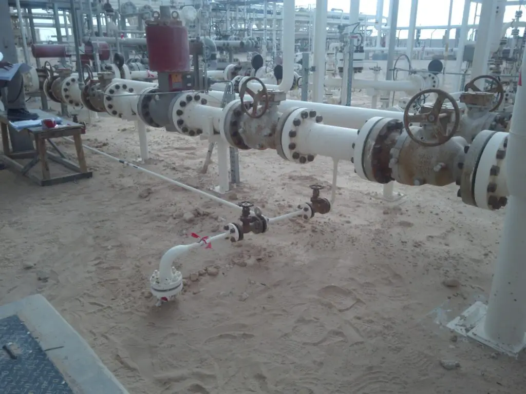
The correct placement of the gasket and proper tightening of bolts in a flanged joint will ensure a leak-free joint. Proper bolt tightening will ensure uniform load distribution in all bolts without damaging the gaskets. The following procedure describes how to tighten flange bolts.
Flange Bolt Tightening Procedure
Before actual tightening starts, the flange, gasket, and bolts/nuts need to be observed as below:
Flange checking points before flange bolt up
Leakage through a flanged joint is prevented as gasket material flows inside the flange surface imperfections and seals them. But there are limitations that a gasket can successfully seal. Hence, Flange surfaces must be checked thoroughly to ensure the absence of large nicks, dents, or gouges. So the flange surface finish must be as per the manufacturer’s recommendation for particular gasket materials. Recommended values of flange surface roughness are as follows:
- Solid Metal Gaskets: 63-80 rms
- Spiral Wound Gaskets: 125-250 rms
- Jacketed or Metal Clad Gaskets: 63-80 rms
Here, RMS stands for root mean square. Roughness is normally specified in millionths of an inch as the average of the peaks and valleys measured from a midline of the flange surface.
A flange is recommended to be machined using a 1/16″ radius, round-nosed tool to have 30-55 serrations per inch in a concentric or spiral pattern.

Check the following points prior to flange bolting.
- Before inserting the gasket in between the pipe flanges, check the flanges are parallel and co-axial (When none of the bolts is installed in the flange).
- As per ANSI B31.3 clause no. 335-C, permitted tolerances are as follows: Flange faces shall be aligned to the design plane within 1 mm in 200 mm(1/16 in. /ft) measured across any diameter; flange bolts holes shall be aligned within 3 mm (1/8 inch) maximum offset.
- If pipe flanges are not meeting the ANSI B31.3 requirement, the piping shall be rectified.
- All gasket seating areas shall be cleaned properly before gasket insertion. If serration is damaged, re-serration must be done.
Checkpoints for Gasket prior to tightening flange bolts
- Ensure the gasket of the correct dimension and of specified material is used.
- The gasket shall be located correctly to ensure full sealing as indicated in the drawing. For example – a gasket on the tube sheet of an exchanger needs to be located so that the outer periphery of the gasket matches the OD of the tube sheet at all points.
- Examine the gasket in advance and ensure that it is free from defects.
Bolts for Pipe Flanges
Bolts create compressive pressure on the flanges and gasket so that leakage is prevented. So, while selecting, the temperature variations in service must be considered. Recommended values of flange bolting temperature are as under.

- Ensure that the material of all bolts and nuts is as specified.
- Bolts & nuts shall be cleaned with suitable solvents like Diesel / CTC using a wire brush, especially in the threaded portion.
- The bolt shall be lubricated with molybdenum disulfide and it is essential, especially in all bolts of size 7/8” and above to check the application as the bolt load developed by torque is dependent on the lubrication of threads.
- It is recommended to avoid the use of short bolts on the flange joints.
Flange Bolt Tightening Procedure
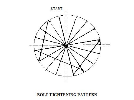
It is important that all bolted joints are tightened uniformly and in a diametrically staggered pattern (A typical sketch is attached in Fig. 3).
In the case of pipe flanges 8″ NB & up to 12″NB and having a pipe with a spacer piece and a minimum of two gaskets (which are getting compressed simultaneously during tightening) the distance between two flanges should be measured at four locations like 12’o clock, 3’o clock’ 6’o clock and 9’on clock positions and maintained equal for even tightening. The tightening shall be gradual and uniform. In case of flanges above 12” NB distance between the flanges shall be measured in 8 locations for uniform tightening.
All stud bolts of 7/8″ and above shall be tightened using a torque wrench. While tightening the bolt with torque wrenches (for pipe / Manway flanges) ensure that the tightening load to each bolt is applied as uniformly as possible. The tightening shall be carried out in three or four stages in steps of 30, 50 & 70 percent of the final torque value. The fourth stage again uses 70 percent of the final torque value.
For heat exchangers flange’s torque values are to be 30,70,100 and 100 percent of the final torque value.
Where recommended use a hydraulic tensioner for bolt tightening following the manufacturer’s recommendations.
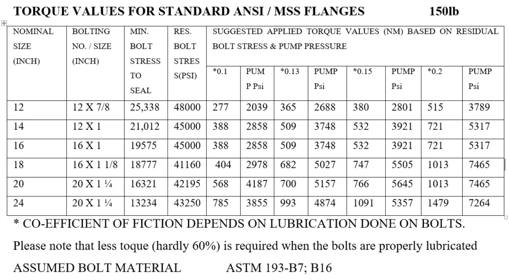
A table is provided in Fig. 4 below to show an example of torques applied for bolt tightening.

Wrong Practices followed during Flange Bolt Tightening
Many a time, plant operators use wrong practices while flange bolt tightening as follows
- Improper sequence of bolt tightening.
- Reuse of old gasket.
- Procurement of un-specified material.
- Improper storage of gaskets.
- Use of many gaskets to fill a large gap between flanges.
- Use of ordinary fasteners instead of high-tensile fasteners
- Use of dirty/rusted fasteners without lubrication.
Few more related articles.
How to Select a Bolt: A definite Guide
Bolting Features in Bolted Connections/Bolted Joints
Guide for Coating Selection for External Bolting to Reduce Corrosion
Collar Bolts To Maintain Removable Bundles in Heat Exchangers


Good, need add sequent flange management as per dia inchi. Please recommended online training flange management. Thanks
Anup: do you have any pre-job checklists that must be done before performing maintenance on a flange in oil and gas industry: 70% of the success any almost any operation is pre-job, appreciate any help you can give us
kind regards
Hasmukh
Dear Mr.Anoon,
Please can you arrange the installation procedure of SDSS piping (600 mm 500mm & 400mm)
Wonderful points you have mentioned in the installation process of Flange Bolt tightening. Please stay informed with your informative thoughts.
Hi Anup,
Just want to pick your brains mate.
In normal operating oil and gas plants, where piping is widespread, ranging from class 150 to 2500, I note that although bolting fasteners on flanged connections are coated with a galvanised or even phosphate type coating and the flange joint and associated piping is coated with an expoxy coating, one very seldom sees the actual flange fasteners (studs (B7) & Nuts (2H)) are also coated with the same epoxy coating as the piping.
Why is it considered poor engineering practice to paint torqued fasteners on flanged joints?
Hope to hear from you soon.
Best wishes,