Normalizing is a widely popular heat treatment process for metals to increase ductility and toughness. This heat treatment is also known as normalizing annealing as the normalizing heat treatment process is very similar to annealing treatment. In this article we will learn more about normalizing; its definition, purposes, process steps, applicability, normalizing vs annealing, etc.
Normalizing Definition/ What is normalizing?
Normalizing is defined as a heat treatment process where a material is heated to a predecided elevated temperature, hold at that temperature for a certain period of time (usually 10-20 minutes), and then allowed to cool freely in the air to reach room temperature. The normalizing process is usually applied to metals that have been subjected to thermal or mechanical hardening processes and require their microstructure to be normalized. After normalizing, the metal gets back its ductility and the hardness is reduced.
Metals Suitable to be Normalized
For the normalizing treatment of a metal, it must be receptive to normalizing. Various metals and alloys are suitable to be normalized like
Iron-based alloys like Carbon steel, stainless steel, alloy steel, cast iron, etc.
Nickel alloys
Copper
Aluminum
Brass
Purpose of Normalizing
The main purposes of the normalizing heat treatment on metals are:
To remove structural irregularities or impurities and defects from the metal.
To improve ductility that has been lost in some metal processing.
To reduce the hardness that has been increased by mechanical or thermal hardening processes.
To increase the toughness of the metal.
To relieve internal stresses.
To get an improvement in machinability.
The Normalizing Process
Similar to annealing the normalizing process also follows three main stages; the Recovery stage, the Recrystallization stage, and the grain-growth stage. In the recovery stages of normalizing, the internal stresses are relieved by heating the material. Then the metal is heated to elevated temperatures above the recrystallization temperature of the metal where new grains are formed. Finally, in the grain growth stage of normalization, the grains develop fully when the material is cooled by air.
Applications for Normalizing
Normalizing treatment finds broad practical applications across several industries like Aerospace, Automotive, Heavy Equipment, Energy, Agriculture, Oil & Gas, etc. Usually, whenever metal is expected to get high residual stresses due to some kind of manufacturing steps, it is always suggested to normalize the metal using the normalizing heat-treatment process. A few examples include:
Carbon steel is normalized when it is cold-rolled to reduce brittleness and increase ductility.
After work hardening of ferritic stainless steel stampings in the automotive industry, they are normalized to regain their mechanical properties.
After the thermal microstructure alteration during welding in nickel-based alloys in the nuclear industry, normalizing is performed.
Normalizing Steel
Steel normalizing is a heat treatment process performed after rolling, welding, or forging processes to refine the distorted grains in the microstructure. The normalizing process of steel involves the following steps:
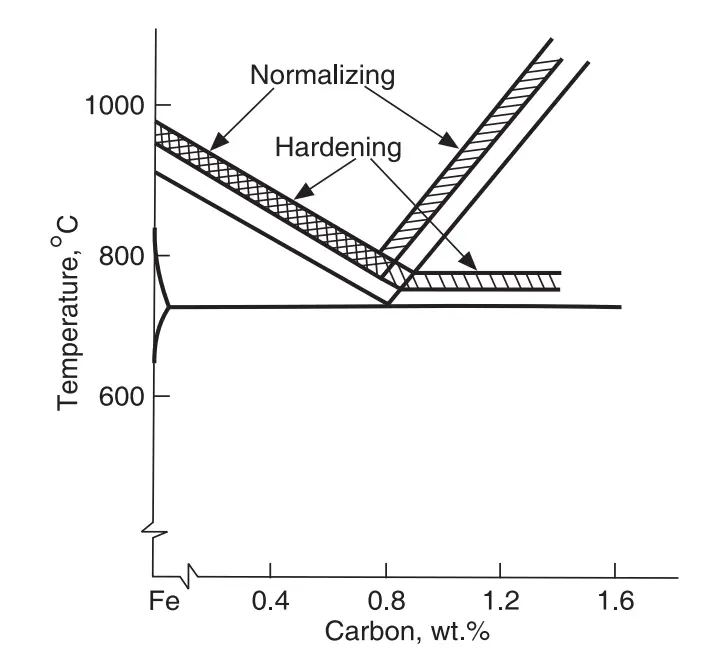
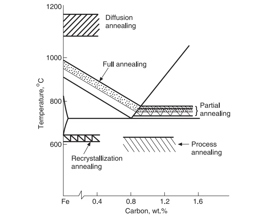
Steel is heated to about 40-500C (Refer to Fig. 1) above the upper critical temperature (A3 or Acm).
The alloy is then held at that temperature for around 10-20 minutes.
Cooling it in still or slightly agitated air to bring back to room temperature.
Fig. 1: Normalizing temperature of Steel
After normalizing, the resultant microstructure is usually perlite. The grain size in normalizing steel is governed by the section thickness. A variation in grain size is observed as the cooling rate varies from the case to the core. The normalizing temperature of steel varies with the carbon content as is clear from Fig. 1. The following table (Table 1) provides recommended normalizing temperatures for steel.
Carbon %
0.1
0.2
0.3
0.4
0.6
0.8
1.0
1.1
1.2
Temperature, 0C
920
900
880
860
840
820
830
900
925
Table 1: Recommended temperatures for normalizing steel
Difference between Normalizing and Annealing
Even though the process steps for normalizing and annealing are almost similar there are specific differences between normalizing and annealing. The differences between annealing and normalizing are provided below in a tabular (Table 2) format.
Normalizing
Annealing
The cooling rate in normalizing is faster than annealing.
Slower cooling rate as compared to normalizing.
Slow cooling in room temperature.
Controlled slow cooling in a furnace.
Mechanical Strength and hardness of normalized components are more.
Strength and hardness are lower as compared to the normalized parts.
Machinability is more improved in normalizing.
Annealed product is soft and thus can stick to the machine during machining.
Slightly less ductility.
More ductility.
Less expensive
Comparatively costly
Table 2: Normalizing vs Annealing
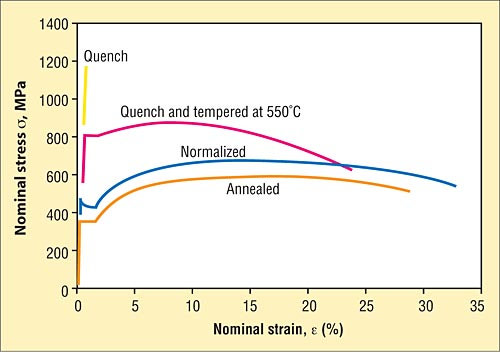
The image in Fig. 2 shows the typical differences in nominal strength between Normalized and Annealed steel.
Fig. 2: Normalized vs Annealed Steel
What Is Annealing Steel | Annealing Process of Steel
Annealing is one of the most popular heat treatment methods to alter the mechanical properties of metals and alloys. Annealing is mostly used to increase the ductility of a material and to reduce the hardness. After annealing treatment, the metals or alloys become more workable. In this article, we will discuss the annealing process in detail.
What Is Annealing?
Annealing is a heat treatment process in which a metal is heated above its recrystallization temperature, kept at that temperature for some time for homogenization, and then cooled slowly to develop an equilibrium structure. In the crystal structure of the metal or alloy being annealed, the number of dislocations is reduced which causes an increase in ductility and relief of residual stresses. Usually for materials that have undergone some cold work or hardening treatment annealing is performed. So the main purposes of an annealing heat treatment are:
To eliminate internal residual stresses that occurred during earlier processing steps.
To improve the machinability of the metal.
To increase ductility which in turn improves formability.
To prevent deformation and cracking.
To reduce hardness and increase toughness.
To improve magnetic properties and decrease electrical resistance.
To refine the grain size.
To reduce the gaseous contents of the metal or alloy.
Stages of the Annealing Process
Every annealing heat treatment process consists of three stages; the Recovery stage, the Recrystallization stage, and the Grain growth stage. These stages work as follows:
Recovery Stage: In the recovery stage of the annealing process, the metal is heated in a furnace and its temperature is raised to such a point where the internal stresses are relieved.
Recrystallization Stage: In this stage, the metal is heated above the recrystallization temperature where new grains form without any residual stresses. Recrystallization is defined as a process where the deformed grains in a metallic structure are replaced by a new set of defect-free grains at a certain specific temperature range known as the recrystallization temperature.
Grain Growth Stage: In this stage of the annealing process, the material is cooled at a pre-decided rate for new grains to fully develop.
Metals for Annealing Treatment
The annealing process is applicable for most of the common materials like Steel, Cast Iron, Aluminum, brass, copper, etc. However, the material selected should be such that its properties can be altered by heat treatment. The majority of the annealing process is done over the steel alloy. All work-hardened steel materials like sheet metals, wires, and welding processes creating high residual stresses must undergo the annealing of steel processes to recover their properties.
What is Annealing Steel and its Types
Annealing steel means heating it to a predetermined temperature, holding it at that temperature for a certain period of time, and finally cooling at a very slow rate. The temperature to which the steel should be heated and the holding time are determined considering various factors like
Chemical composition of the steel (%Carbon content)
Shape and size of steel component( thickness)
Final properties desired.
Depending on the temperature of annealing treatment, phase transformation, and purpose, the annealing of steel is classified into various groups.
Steel Annealing types based on annealing temperature
Considering the steel annealing temperature, the annealing process is sub-divided into three classes. They are
Full Annealing
Partial annealing, and
Sub-critical annealing
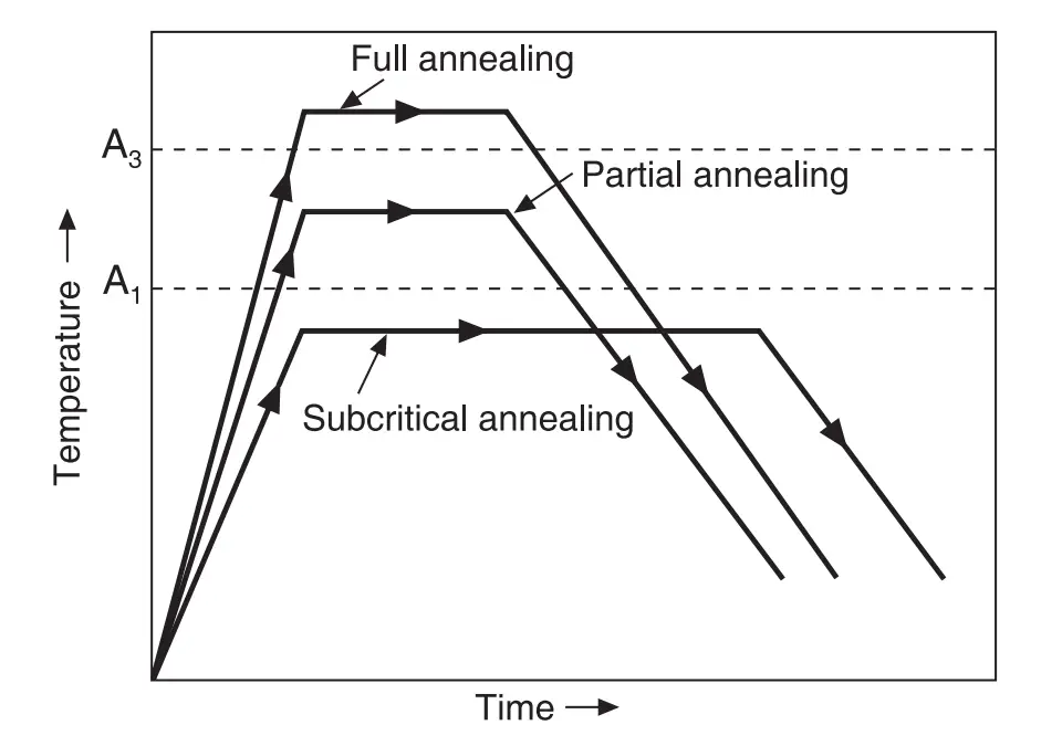
Refer to Fig. 1 below that shows the temperatures at which Steel alloy should be heated for the above-mentioned annealing processes.
Fig. 1: Types of Annealing based on Annealing temperature
As understood from the above figure, in the full annealing process, steel is heated above the upper critical temperature (A3) and then cooled very slowly. In the case of partial annealing, steel is heated to a temperature that lies between lower (A1) and upper (A3 or Acm) critical temperature and then cooled slowly. Partial annealing is also known as inter-critical annealing or incomplete annealing. For the subcritical annealing process, the steel is heated below the lower critical temperature (A1). No phase change takes place in subcritical annealing and thus only recrystallization, softening, recovery, and grain growth occur.
Annealing Steel types based on specific purposes
Based on the specific purposes of annealing steel, the process is grouped into various types. They are:
Diffusion Annealing
Full Annealing
Spheroidizing Annealing
Recrystallization Annealing
Isothermal Annealing
Process Annealing
Full Annealing of Steel
Full annealing of steel is also known as phase recrystallization annealing. This process ensures the refinement of grains and the elimination of structural inhomogeneity. The process of full annealing of steel consists of heating the steel alloy to 30 to 500C above (A3 for hypo-eutectoid steels, A1 for eutectoid steel) followed by slow cooling. Almost all castings, forgings, and rolled stocks are provided with this treatment to get enhanced mechanical properties.
Diffusion Annealing of Steel
The purpose of diffusion annealing is to eliminate inhomogeneities of the chemical composition, dendrites, and columnar grains which appear during the crystallization of alloys. Diffusion annealing is usually carried out at a temperature of 1100–13000C (2012–23720F) and then the steel is held at this temperature for 10-20 hours, followed by slow cooling. Diffusion annealing is used to smooth out a difference in the content of alloying elements due to the inter-crystal liquation and chemically homogeneous steel is obtained. To improve the properties of medium-purity steels, this type of annealing is used.
Isothermal Annealing of Steel
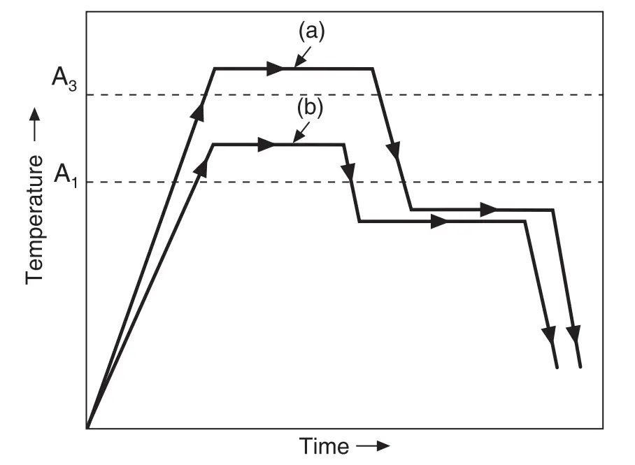
In isothermal annealing, after heating the steel to above critical temperatures is held at this temperature for quite some time. It is then rapidly cool to 600-7000C by rapidly transferring the steel to another furnace maintained at the desired temperature. This temperature is maintained for some time and then cooled in the air. This process improves machinability and a better surface finish during machining. The heat treatment cycle is shown in Fig. 2
Fig. 2: Heat treatment cycle in Isothermal Annealing: a) hypo-eutectoid steel and b) eutectoid steel
Recrystallization Annealing of Steel
To increase the ductility of cold-worked steels, recrystallization annealing is used. The temperature at which the steel is to be heated depends on the amount of prior deformation, chemical composition, holding time, and initial grain size. Usually, alloy steels and high carbon steels require a higher temperature.
Process Annealing of Steel
Process annealing of steel consists of heating it below A1 temperature and holding it at this temperature for sufficient time and then cooling it. It is usually an intermediate operation for processing the steel further. Process annealing treatment is widely given for steel fabricated by extrusion, stamping, upsetting, and drawing. The temperatures at which steel should be heated for various annealing treatments are provided in Fig. 3 below:
Fig. 3: Heating temperatures for various annealing processes
Spheroidizing Annealing of Steel
Spheroidizing annealing results in carbide spheroids in a ferrite matrix. The degree of spheroidization varies according to heat-treatment temperature and holding time. Various processes are available to get spheroid structures in steel. To improve machinability and ductility, Spheroidizing Annealing is often performed for alloy steels and high carbon steels.
Does annealing increase strength?
Yes, the annealing treatment of metals increases the strength by reducing dislocation sources. The annealing process improves the ductility of material by strengthening grain boundaries’ resistance to intergranular cracks.
Do you quench after annealing?
For annealing of steel, the cooling method applied is slow cooling, not immediate. So, in general, steel is not quenched after annealing.
What are the types of annealing?
The annealing process can be categorized into several types:
Complete Annealing.
Partial Annealing
Isothermal Annealing.
Spherical Annealing.
Recrystallization Annealing.
Diffusion Annealing.
Stress Relief Annealing.
What industries use annealing?
Manufacturing industries dealing with Steel, Cast Iron, Aluminum, Copper, Brass, etc use the annealing process widely. Usually, materials are annealed before extreme forming or drawing operations.
What is a Thrust Block? It’s Design, Construction, Types, Working, Differences with Anchor Block
A thrust block is a concrete pipe restraint that prevents the mainline from moving by transferring pipe loads (mainly due to pressure thrust) to a wider load-bearing surface. Usually, thrust blocks are provided for buried pipelines at fittings requiring branching or direction change. The thrust forces generated at the directional changes or tee junctions due to internal pressure thrust are taken care of by these thrust blocks, which prevents the separation of pipe joints on these pipe fitting locations. Thrust blocks are also known as thrust restraints. Thrust blocks are also sometimes referred to as anchor blocks.
What is a Thrust Block?
A thrust block is a concrete structure made to handle the forces from fluid moving through pipes. These forces generated by pressure thrust are directed along the axis of the pipe. The thrust force, if not mitigated/absorbed, can cause significant movement or stress within the pipe system. This could damage the pipe system. The thrust block helps by transferring these forces over a larger area, like the surrounding soil or a concrete base, to keep the pipe stable and in position.
Thrust blocks in piping systems are strategically placed at locations where the direction or diameter of the pipes changes, such as bends, tees, dead ends, and reducers. These points experience significant stress, making thrust blocks crucial for managing this stress.
Why are Thrust Blocks Required? | Purpose of Thrust Blocks
A thrust block’s main purpose is to handle the thrust force and stabilize the pipes, preventing unwanted movement. This helps maintain the system’s integrity and reliability.
Fluids traveling through a piping system under internal pressure exert a thrust force at all bends, tee junctions, reducers, and stop ends. The magnitude of these forces is usually so high that they can easily weaken the joints and even cause leakage or failure of the piping/pipeline system. With an increase in the piping size, these forces increase further. Installation of a thrust anchor block partially absorbs that pressure thrust force and the remaining is transferred to the surrounding soil.
However, note that anchor thrust blocks are rarely used for steel pipes, as the thickness of welded pipes is normally sufficient to prevent joint separation. However, thrust blocks are quite common in ductile iron, GRP/FRP, PE/HPDE, and PVC piping systems.
How Thrust Blocks Work | Thrust Block Working
Thrust blocks or anchor blocks are key parts of unrestrained piping systems. They manage the forces created by moving fluids in the pipes. These forces are strongest where the pipe changes direction, like at bends, or where the pipe ends, such as at caps or valves. Here’s how they work:
Functionality of Thrust Anchor Blocks
Counteracting Forces:
When fluid moves through a pipe, especially under high pressure, it exerts a force in the flow direction. At a bend or change in direction, it generates a reaction force in the opposite direction to fluid flow. At the elbow center, both these forces add up and can cause the pipe to move or shift. A thrust block absorbs these forces and keeps the pipe in place, preventing joint failures or leaks.
Force Distribution:
Thrust blocks spread the forces over a larger area. Instead of the pipe handling all the stress, which could cause damage, the thrust block distributes the force across a wider area, often into the surrounding soil or concrete.
Thrust Block Design
As already mentioned, a thrust block is a large concrete block. It has to be sized properly so that the thrust block is capable of withstanding the pressure thrust force. Even though thrust blocks are specifically designed to absorb pressure thrust force, they should be designed to withstand thermal forces as well. Sometimes the thermal load can be more than the pressure thrust load. So, it is suggested to find out both thermal and pressure loads and consider the maximum force value for the calculation of the thrust block design. So, to size a thrust block, the first requirement is the thrust force.
Thrust Force Calculation for Anchor Thrust Block Design
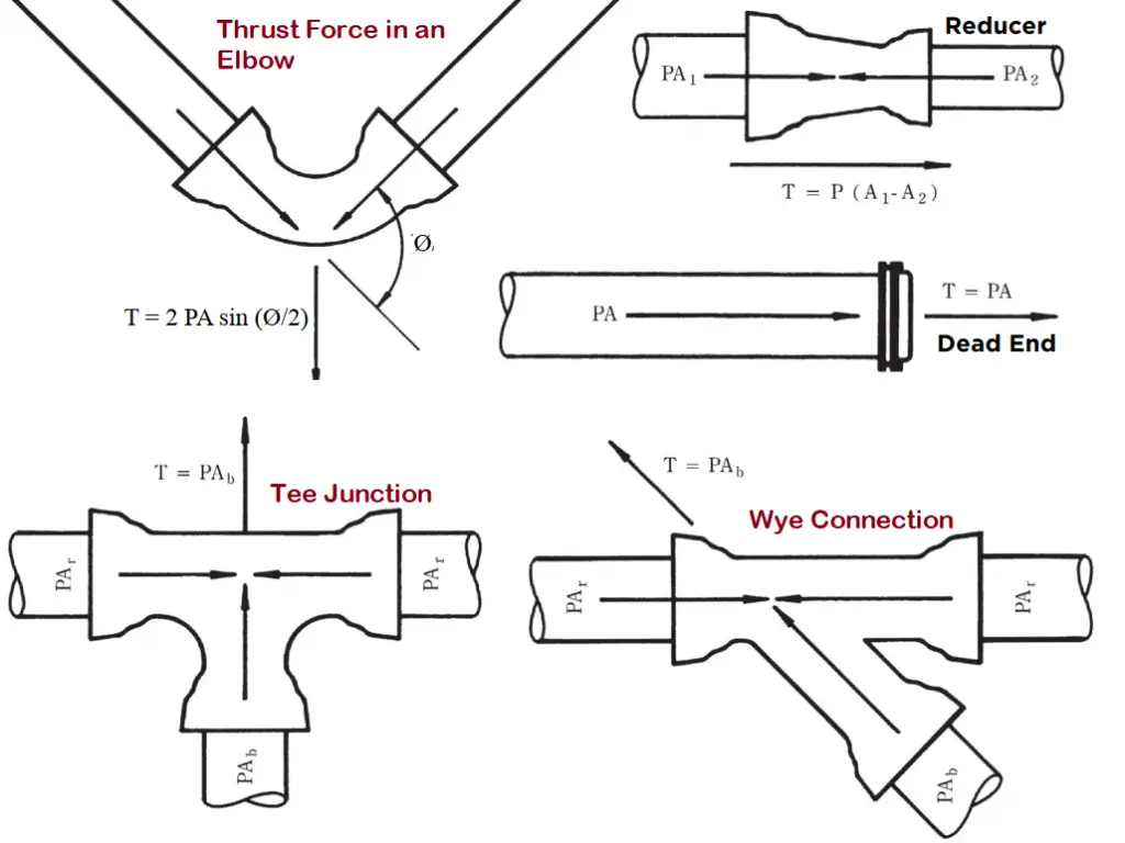
The raw formula for the calculation of thrust force is Pressure multiplied by the internal cross-sectional area of the pipe. However, depending on various pipe configurations, this formula requires modification. The following image (Fig. 1) provides some typical thrust force calculation formulas for ductile iron pipes (Reference: Ductile Iron Pipe Research Association)
Fig. 1: Thrust force formula for various piping configurations
Thrust Force on an Elbow or Bend: To Calculate the design thrust force or resultant force for bends the following formula can be used. Thrust force, F = 2 P A sin (ϕ/ 2) Where: P = design pressure, A = cross-sectional area of the pipe, and ϕ = angle of the bend.
Thrust force on Plugs or Caps: The Thrust force in a plug or cap is equal to the design pressure (P) times the cross-sectional area (A) of the pipe. (Thrust force, F = P A).
Thrust force for Tee connections: The thrust force generated in a Tee connection is calculated as F=P Ab. Where P=internal design pressure and Ab= cross-sectional area of the branch pipe.
Thrust force calculation of Pipe reducers: The design thrust force for piping reducers/expanders is equal to the design pressure (P) times the difference of the cross-sectional areas of the large (A1) and small end (A2) sizes of the reducer. Hence, thrust restraint force, F = P (A1 − A2)
The thermal load can be directly taken from any stress analysis software like Caesar II, Start-Prof, Rohr-II, Caepipe, or Autopipe.
Once thrust force (Let’s assume the calculated value of thrust force is F) is known, we have to calculate the area required to withstand that thrust force. The area can be calculated by knowing the soil properties where the thrust restraint will be installed. The required soil parameter is the bearing pressure (Let’s assume it to be Pb) of the soil. So, the minimum area required (A) can be easily calculated by dividing the thrust force by soil bearing pressure. Hence, the minimum required area, A=F/Pb. This minimum area should be multiplied by a factor of safety (usually 1.5) to get the actual area.
Once the minimum required area is known, the thrust block geometry can be designed after knowing the type of pipe fitting where the thrust block will be installed. So, the term “thrust block calculation” means the calculation of thrust force and the required area for a thrust block that is sufficient to absorb the thrust force.
Thrust Block Construction
Concrete is the most popular element for constructing thrust blocks. Concrete material is strong and dense enough to arrest the generated thrust forces. The design of these blocks—both in size and shape—depends on several key factors:
Pipe Diameter and Material: The dimensions and the material of the pipe influence the thrust block’s requirements.
Fluid Pressure and Velocity: Higher pressure and faster-moving fluids necessitate larger or more robust thrust blocks.
Pipe Bend Angles: The configuration of pipe bends affects how forces are distributed, impacting thrust block design.
Soil Conditions: The type of soil surrounding the pipe must support the thrust block adequately to prevent shifting or compression.
For thrust blocks to perform their function effectively, they must interact properly with the surrounding environment.
Soil: The soil must support the thrust block without excessive compression or shifting. Often, soil testing is conducted to determine the correct design and sizing.
Concrete and Reinforcement: To enhance their durability, concrete thrust blocks are typically reinforced with steel bars or mesh, which helps them withstand the forces without cracking or deteriorating.
Factors Affecting the Size of a Thrust Block
So, as specified above, there are four parameters required for sizing a thrust block. Those are:
Maximum Internal pressure to calculate thrust force
Pipe Size to calculate pipe cross-sectional area for calculating thrust force.
Soil bearing load to find out the area required for the thrust block and
Type of fitting (& Degree of angle in case of bends) to define the geometry of the thrust block
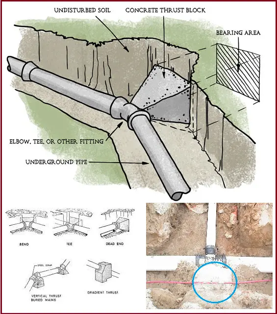
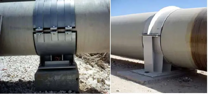
Fig. 2 below are some images of typical thrust blocks.
Fig. 2: Typical thrust block images
Key Components of a Thrust Block and Their Roles
Thrust blocks are essential elements in piping systems designed to manage and distribute the forces generated by fluid flow. Understanding the thrust block component details that make up a thrust block and their functions is crucial for ensuring its effectiveness and durability. Now we will describe the primary components and their roles in the construction of thrust blocks.
Concrete
Concrete serves as the primary material for thrust blocks due to its impressive strength and durability. It is capable of absorbing and redistributing large forces, which helps prevent pipe displacement or damage under pressure.
Mix Composition: The concrete used in thrust blocks typically includes a carefully measured blend of cement, water, aggregates, and sometimes additives. These elements are combined to enhance strength, reduce curing time, and improve overall durability.
Curing Process: Achieving the desired strength and longevity of the concrete requires proper curing. This process involves maintaining the right moisture levels and temperature until the concrete reaches its optimal strength.
Reinforcement
To bolster the structural integrity of concrete thrust blocks, reinforcement is often used. This reinforcement generally comes in the form of steel rebar or wire mesh.
Steel Rebar: Reinforcing bars are embedded within the concrete to resist tensile and shear stresses. The specific layout and sizing of rebar are determined based on expected loads and environmental conditions.
Wire Mesh: For smaller or less critical thrust blocks, wire mesh may be employed. It helps evenly distribute stresses and mitigate the risk of cracking.
Formwork
Formwork refers to the molds or frames used to shape the concrete as it sets. The design and material of the formwork are crucial for ensuring that the thrust block achieves its intended shape and effectiveness.
Materials: Formwork can be constructed from wood, metal, or plastic, depending on the project’s requirements and whether it will be reused.
Design: The formwork must be designed to handle the anticipated forces and accommodate the pipe and soil interface. It should also be easily removable to avoid damaging the set concrete.
Interface Material
Interface materials are placed between the pipe and the concrete to protect the pipe from potential damage due to direct contact with the concrete. They help distribute loads and accommodate minor movements and vibrations.
Rubber or Neoprene Pads: These materials are commonly used to cushion the pipe and reduce stress concentration at contact points.
Sand or Gravel: In some designs, a layer of compacted sand or gravel is used around the pipe before pouring concrete. This layer provides a softer bedding that helps absorb some of the forces.
Protective Coatings
To extend the lifespan of thrust blocks, particularly in harsh environments, protective coatings can be applied to the concrete.
Waterproofing Agents: These coatings prevent water ingress, which can cause freeze-thaw damage and corrosion of reinforcements.
Chemical Resistant Coatings: In industrial settings where chemical exposure is a concern, coatings resistant to chemicals protect both the concrete and reinforcement from deterioration.
Expansion Joints
In scenarios where temperature variations are significant or thrust blocks are large, expansion joints can be incorporated. These joints allow for the expansion and contraction of both the concrete and the pipe, preventing damage and undue stress.
Materials: Expansion joints are usually made from compressible materials such as fiberboard or rubber.
Placement: They are strategically positioned within the thrust block and around the piping to facilitate movement while maintaining structural integrity.
Types of Thrust Blocks
Based on specific applications and environmental conditions, Thrust blocks are designed from different materials. Depending on the constituent material, the most common types of thrust blocks are discussed below:
1. Concrete Thrust Blocks
Concrete thrust blocks are the most prevalent type due to their durability, strength, and versatility. Concrete’s ability to absorb and distribute large forces makes it well-suited for a wide range of applications.
Pre-cast Concrete Blocks: Manufactured in a controlled environment, pre-cast concrete blocks ensure consistent quality and are typically used in standard applications where forces are predictable and uniform. Their pre-made nature allows for quick installation and reliable performance.
Poured-in-Place Concrete Blocks: For more complex or customized applications, poured-in-place concrete blocks are ideal. This method allows for a tailored fit, adapting to specific site conditions and pipe configurations. It ensures that the thrust block integrates seamlessly with the surrounding environment.
2. Steel Thrust Blocks
Steel thrust blocks are less common but offer advantages in certain situations. They are particularly useful in applications where a high strength-to-weight ratio is critical, such as in elevated or suspended piping systems.
Steel Plate Blocks: These blocks are constructed from thick steel plates welded together to form a robust anchor for pipes. They are often employed in industrial settings, where high-pressure pipes require substantial support.
Steel Rods or Cable Systems: In some scenarios, steel rods or cables are used to anchor pipes to stable structures like bedrock or building foundations. This approach provides a secure attachment in environments where traditional concrete might not be practical.
3. Composite Material Thrust Blocks
Composite material thrust blocks are gaining popularity due to their advanced properties, which cater to specific needs such as weight reduction or enhanced environmental resistance.
Fiberglass: Renowned for its resistance to corrosion and lightweight nature, fiberglass thrust blocks are used in harsh environments like chemical processing facilities or marine applications. Their durability in aggressive conditions makes them a valuable choice.
Polymer Concrete: Combining the strength of traditional concrete with the advantages of plastics, polymer concrete is an excellent choice for areas with acidic soils or high moisture levels. It offers a balance of strength, light-weight, and resistance to environmental factors.
What is a thrust block on a pipeline?
Thrust blocks in a pipeline refer to the concrete blocks provided in buried pipelines for preventing movement and absorbing thrust forces. For large buried pipelines, the pressure thrust force becomes too large and is usually exerted on elbows and tees. Thrust clocks are therefore added in those regions to avoid the failure of piping components.
How does thrust block work?
Thrust blocks are sized to have a larger bearing area, which transfers the thrust force from pipe fittings to the soil and thereby safeguarding from joint failures.
Where are thrust blocks needed?
Conventionally, thrust blocks are needed in underground pipeline directional changes. So, in all the fittings like elbows, wyes, Tees, and Pipe Caps, wherever the pipeline changes its direction.
What is the Difference Between an Anchor Block and a Thrust Block?
The terms “anchor block” and “thrust block” are used synonymously in most of the cases as the major function is almost similar. Both thrust block and anchor block in pipelines serve as anchors and fix the pipeline at location. However, the actual difference arises in the use of proper application. The main aim of thrust blocks is to absorb and distribute pressure thrusts whereas the main aim of anchor blocks is to fix the pipeline in position. Even though at the end both serves the same purpose. Other differences between a thrust block and an anchor block are
Thrust blocks are installed only in changes in pipeline directions but anchor blocks can be installed in line with pipe fittings, in between flanges, tie-in connection with dissimilar materials, etc.
Thrust blocks are usually cast with a small part of the pipeline fitting inside it. However, the anchor block usually cast all around (360 Degrees) to encapsulate the full fitting or pipe part.
What is Viscosity? | Factors Affecting Viscosity | Newton’s law of Viscosity
“What is viscosity?” is an often-asked term in fluid mechanics. Viscosity is a fluid property and is very important for studying fluid flow behavior. All kinds of fluids, whether they are in a liquid state or gaseous state, possess viscosity. Viscosity is a fundamental property of fluids that plays a crucial role in various fields, including physics, engineering, chemistry, and even biology. It describes a fluid’s resistance to deformation and flow, which makes it essential for understanding the behavior of liquids and gases in both natural and industrial processes. In this article, we will explore more details about the term “viscosity,” its definition, significance, units, equations, and values.
Definition of Viscosity
The term “viscosity” has its root in the Latin term “viscum,” which refers to a viscous glue originating from mistletoe berries. In fluid mechanics, viscosity is defined as the measure of a fluid’s resistance to fluid flow under an applied force. It can be intuitively understood as the “thickness” or “stickiness” of a fluid. For a fluid in motion, viscosity describes internal friction. So, a fluid having a large viscosity provides more internal friction to resist flow, whereas a fluid with a lower viscosity provides little friction. In general, liquids have more viscosity than gases.
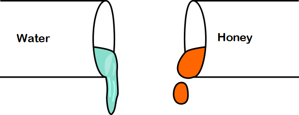
The concept of viscosity will be more clear if we consider the following example. If we take water and honey in a pot and try to pour, we find that water is flowing more smoothly and quicker than honey. This is because honey is more viscous than water. So, honey provides more resistance to motion than water, and that is why water moves more freely than honey.
Fig. 1: Viscosity of Water vs Honey
Significance of Viscosity
The viscosity of a fluid is opposite to the fluidity that denotes how easily a fluid can flow. It is basically the internal friction between the molecules comprising the fluid. For fluid transportation and lubrication engineering, injection molding, spraying, and surface coating applications, viscosity plays a major role as it controls the flow of the liquid. Knowing the viscosity data is very important to predict fluid behavior. For example, if the tomato ketchup inside the tube does not have the correct viscosity, it may not flow from the tube or flow too much, all of certain.
Understanding viscosity is vital in a range of disciplines:
In engineering, it influences the design of pipelines and pumps.
In food science, it affects texture and mouthfeel.
In pharmaceuticals, it determines how drugs are delivered.
Symbol of Viscosity
Mathematically, viscosity can be defined as the ratio of viscous stress (shear stress) to the rate of change of deformation. The symbol of viscosity is µ (Greek letter mu). Hence,
Viscosity, µ=Shear Stress/strain rate=τ / (du/dy) So, µ=τ / (du/dy)……(1)
The above symbol for viscosity µ is widely used. However, some physicists and chemists prefer to use η (the Greek letter eta) as the symbol of viscosity.
Units of Viscosity
From the above mathematical equation, we know that viscosity = stress/strain rate. The unit of stress in SI unit =N/m2. The unit of Strain rate = (m/s)/m.=1/s Hence, the unit of viscosity = (N/m2)/(1/s)=N-s/m2, and the dimension of viscosity is (force X time/area). The above viscosity discussed is also popular as dynamic viscosity or absolute viscosity. Hence, the unit of viscosity or dynamic viscosity in the SI system is N-s/m2 or pascal-second.
Often, the unit of viscosity is denoted by Poise or Centipoise. In the CGS unit system, the unit of dynamic viscosity is “Poise” named after Jean Léonard Marie Poiseuille. The relation between Pascal-Second and poise is given below:
1 Pascal-Second= 10 Poise or 1Pa-s=10P
Types of Viscosity
There are two types of viscosity, relevant in different contexts.
Dynamic (Absolute) Viscosity
Dynamic viscosity, often denoted by the symbol μ (mu), is a measure of a fluid’s internal resistance to flow when an external force is applied. It is expressed in units of Pascal-seconds (Pa·s) or poise (P), where 1 P = 0.1 Pa·s.
Kinematic Viscosity
Kinematic viscosity, represented by the symbol ν (nu), measures the fluid’s resistance to flow under gravity. It is defined as the ratio of dynamic viscosity to fluid density and is usually expressed in square meters per second (m²/s) or centistokes (cSt).
What is Kinematic Viscosity?
Kinematic viscosity or momentum diffusivity is defined as the ratio of dynamic viscosity to fluid density. The symbol of kinematic viscosity is ν (Greek letter nu). So, mathematically the formula for kinematic viscosity is given by ν=µ/ρ.
Now we just learned that the unit of dynamic viscosity=N-s/m2. Unit of fluid density=Kg/m3. Hence, the unit of kinematic viscosity =(N-s/m2)/(Kg/m3)=(Kg-m/s2)*(s/m2)*(m3/Kg)=m2/s. Accordingly, the dimension of kinematic viscosity is (length2/time). In fluid dynamics, working with kinematic viscosity is more convenient.
Measuring Viscosity
It is well known that measuring the viscosity of fluids is very important to understand the flow characteristics of those fluids. There are various types of instruments by which viscosity can be measured. Those viscosity-measuring devices are known as viscometers and rheometers. Common, widely used instruments for measuring viscosity are:
Capillary Viscometer
Falling Sphere Viscometer
Vibrating Viscometer
Rotational Viscometer
Microfluidic Rheometers
Zahn Cup
Fluorescence correlation spectroscopy
Acoustic rheometer
Factors Affecting Viscosity
There are various factors that affect the viscosity of a fluid. Those are:
Fluid Temperature: Usually the viscosity of liquids decreases with an increase in temperature. On the contrary, the viscosity of gases increases with an increase in temperature.
Flow Conditions: For laminar flow, the viscosity of liquid remains constant while for turbulent flow viscosity changes.
Pressure: With an increase in pressure, the viscosity of gases usually increases. Liquids being incompressible does not have much impact.
Multiphase flow: The viscosity of multiphase flow is affected by the volume of each phase.
Shear Rate: In non-Newtonian fluids, viscosity is dependent on shear rate. For example, shear-thinning fluids decrease in viscosity with increased shear rate, while shear-thickening fluids increase in viscosity under the same conditions.
Viscosity Measurement Methods
Measuring viscosity is essential for both theoretical and practical applications. Several methods exist, each with its advantages and disadvantages.
Capillary Viscometers
Capillary viscometers operate by allowing a fluid to flow through a narrow tube. The time taken for a certain volume of fluid to pass through the tube is measured, allowing for the calculation of viscosity. These are particularly effective for low-viscosity fluids.
Rotational Viscometers
Rotational viscometers measure the torque required to rotate a spindle immersed in the fluid. The viscosity is derived from the relationship between torque and rotational speed. This method is suitable for a wide range of viscosities and provides real-time data.
Falling Sphere Viscometers
This method involves dropping a sphere through the fluid and measuring the time it takes to fall a certain distance. The viscosity can be calculated based on the sphere’s terminal velocity, density of the sphere, and the fluid’s density.
Oscillatory Viscometers
Oscillatory viscometers use a vibrating element to measure the fluid’s resistance to oscillatory motion. This method is particularly useful for non-Newtonian fluids and provides information about both viscosity and elasticity.
Viscosity of Water
The viscosity of water at 200 C is 1 centipoise or 1 cP. As for liquids, the viscosity decreases with an increase in temperature, the same is true for water. The following table provides the dynamic viscosity of water with respect to various temperatures.
Temperature (°C)
Viscosity (cP or mPa·s)
10
1.3059
20
1.0016
30
0.79722
50
0.54652
70
0.40355
90
0.31417
100
0.2822
Table 1: Viscosity of Water with respect to Temperature
Kinematic Viscosity of water
The kinematic viscosity of water can easily be obtained by dividing the above dynamic viscosity values by the water density. Table 2 below provides the kinematic viscosity of water.
Temperature (°C)
Kinematic Viscosity (m2/s X 10-6)
10
1.3059
20
1.004
30
0.801
50
0.553
70
0.413
90
0.326
100
0.294
Table 2: Kinematic Viscosity of water with respect to temperature
Viscosity of Some Common Substances
The following table states the viscosity of some popular substances.
Substance
Temperature (°C)
Viscosity (mPa·s)
Benzene
25
0.604
Air
25
18.5×10⁻³
Mercury
25
1.526
Whole milk
20
2.12
Dark beer
20
2.53
Olive oil
26
56.2
Honey
20
2,000–10,000
Ketchup
25
5,000–20,000
Peanut butter
–
104–106
Pitch
10–30 (variable)
2.3×10¹¹
Table 3: Viscosity of some common fluids
Newton’s law of Viscosity
The relationship between the shear stress and the shear rate of fluid under mechanical stress is established by Newton’s law of viscosity. For a given temperature and pressure, Newton’s viscosity law states that the shear stress between two adjacent layers in a fluid is proportional to the velocity gradients between those layers. In another way, it can be stated that the ratio of shear stress to shear rate in a fluid is a constant, and is defined as the coefficient of viscosity. Newtonian fluids obey Newton’s law of viscosity. Non-Newtonian fluids do not follow Newton’s law of viscosity and hence their viscosity varies and is dependent on the shear rate. Dynamic viscosity is the coefficient of viscosity as defined in Newton’s law of viscosity. Equation 1 mentioned above is basically a mathematical representation of Newton’s law of viscosity.
Practical Applications of Viscosity
The concept of Viscosity is used widely in science and technology. The following examples can easily substantiate the applications of viscosity:
The molecular weight of organic liquids is determined using the knowledge of viscosity.
In lubrication engineering viscosity data and its variation with temperature is an absolute necessity to decide suitable lubrication for specific equipment. For example, light machines use low viscous liquids whereas highly viscous oils are used in heavy machines.
For preparing various medicines like syrups viscosity data is required.
Cooking oils, fats, butter, etc are manufactured to provide a specific viscosity.
Gums, coolants, petrol as a cleaner, brake fluid, cosmetics, food products, etc all require viscosity data during production to work smoothly.
Blood circulation inside our body depends on the viscosity of blood.
In the cosmetic industry, the texture of lotions and creams is largely determined by their viscosity.
Other applications of viscosity can be described as follows:
Viscosity has vast implications across various industries, impacting everything from manufacturing to healthcare.
Industrial Applications
In manufacturing, understanding the viscosity of materials is crucial for processes like mixing, coating, and pumping. For example, in the paint industry, the viscosity of the paint affects application methods and drying times.
Biological Applications
In biology, the viscosity of blood is a vital parameter that influences circulation and oxygen transport. Abnormal viscosity can indicate medical conditions, making its measurement essential in clinical settings.
Environmental Science
In environmental science, viscosity plays a role in the movement of pollutants in water and soil. Understanding how viscosity affects dispersion and degradation can inform remediation efforts.
Food Science
In the food industry, viscosity impacts the texture and stability of products like sauces, dressings, and emulsions. Quality control measures often include viscosity testing to ensure product consistency.
Frequently Asked Questions-Viscosity
What is viscosity?
Viscosity is a measure of a fluid’s resistance to flow. It describes how thick or sticky a fluid is, influencing how easily it can be poured or spread.
What does high viscosity mean?
High viscosity usually means the liquid is thicker. The fluid with high viscosity offers greater flow resistance. Let’s describe the term high-viscosity with an example. Among, the two fluids, water, and honey, honey has a high viscosity as compared to water. So, the resistance force against the flow of water will be less as compared to honey.
What are the Types of Viscosity?
Engineering fluid mechanics provides two types of viscosity; Dynamic Viscosity and Kinematic Viscosity.
Is water viscous?
Viscosity is the property of any fluid. Water being a fluid, specifically liquid, is vicious.
How is viscosity important?
Fluid Viscosity is an important parameter for fluids. For food industries, viscosity provides the texture of food. In some situations, high viscosity is considered to be of superior quality as compared to thin liquids.
Which is the most viscous?
Pitch is the most viscous liquid. Glycerine and lubricating oil also have high viscosities.
How is viscosity measured?
Viscosity can be measured using several methods, including:
Capillary Viscometers: Measure the time it takes for fluid to flow through a narrow tube.
Rotational Viscometers: Measure the torque required to rotate a spindle in the fluid.
Falling Sphere Viscometers: Calculate viscosity based on the time a sphere takes to fall through the fluid.
Oscillatory Viscometers: Assess the fluid’s resistance to oscillatory motion.
What factors affect viscosity?
Viscosity is influenced by several factors:
Temperature: Generally, higher temperatures decrease the viscosity of liquids.
Pressure: In most liquids, higher pressure increases viscosity.
Fluid Composition: The chemical makeup and additives can alter viscosity.
Shear Rate: In non-Newtonian fluids, viscosity can change with the rate of shear.
How does viscosity relate to everyday life?
Viscosity impacts various daily activities, such as cooking (the thickness of sauces), automotive (engine oil performance), and cosmetics (the texture of creams and lotions).
Can viscosity change with time?
Yes, some fluids can experience changes in viscosity over time due to factors like temperature fluctuations, chemical reactions, or aging.
What is apparent viscosity?
Apparent viscosity is a term often used in non-Newtonian fluids that do not have a constant viscosity. This type of viscosity can vary depending on the shear rate, making it essential for characterizing complex fluids like polymers and biological fluids.
Does viscosity mean thickness?
Viscosity and thickness are related but not synonymous. Viscosity refers to a fluid’s resistance to flow, while thickness (or consistency) describes the physical property of how “thick” or “thin” a fluid appears. For example, honey is both thick and has a high viscosity, meaning it flows slowly. Water, on the other hand, is thin and has low viscosity, flowing easily. In summary, while viscosity can influence how thick a fluid feels, it specifically measures flow resistance rather than just physical thickness.
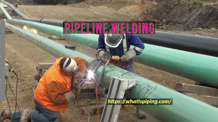
What is Pipeline Welding? | Methods of Pipeline Welding
Pipelines are used to transport gas, water, oils, and other liquids from one point to the other. And as all pipes are produced at a fixed length, there is a requirement of welding to join pipes and make kilometers of pipelines. So, pipeline welding is a very important activity in pipeline construction and is always a demanding profession. Pipe and Pipeline welders are required in construction industries, oil and gas fields, water industries, fabrication shops, nuclear energy industries, etc to lay new pipelines or repair an old pipe.
Pipeline welding is popular as girth welding which is performed along the circumference of the pipes to be connected. As compared to pipe welding in usual plants, pipeline welding poses various additional challenges. Pipeline welding should conform to the relevant ASME codes like B31.4, B31.8, ASME BPVC, etc.
Note that there is a specific difference between pipe welding and pipeline welding. Pipe welding normally refers to the welding of pipes inside chemical plants and oil refineries. Inside the plant a varying range of pipe sizes and materials require welding. On the contrary, pipeline welding concentrates on welding pipes of uniform size and material spread over hundreds of kilometers.
Widely used Pipeline Welding Processes
Usually, the following types of welding processes are widely used for pipeline welding:
Shielded Metal Arc Welding
Gas Metal Arc Welding
Flux-Cored Arc Welding
Submerged Arc Welding
Gas Tungsten Arc welding
Pipeline Welding by Shielded Metal Arc Welding (SMAW)
Shielded Metal Arc Welding of pipelines is also known as Stovepipe welding. In SMAW the pipelines are welded by melting the electrodes with the heat generated by an electric arc. The number of passes required usually varies with the pipe thickness, electrode size, welding position, and the current used for pipeline welding. The usual thumb rule for pipeline welding by SMAW is to consider one pass for each 1/8 inch(3.2 mm) of pipe thickness. Electrode diameters for SMAW pipeline welding normally vary from 1/8 inch to 3.16 inches (3.2 mm to 4.8 mm).
The main advantage of pipeline welding by SMAW is that the welding equipment is simple and portable. Also, no flux or shielding gases are required during welding. However, the productivity of this method is less due to lower travel speed.
Pipeline Welding by Gas Metal Arc welding (GMAW)
Pipeline welding by gas metal arc welding provides high productivity as compared to the SMAW method But this method required better control of welding variables for efficient quality work. High deposition efficiency (90 to 97%) with low fume generation are advantages of GMAW. This is generally performed using semi-automatic/ automatic equipment and the welding cost is increased.
Pipeline Welding by Flux-cored Arc Welding
Gas Shielded Flux-cored arc welding is performed using semi-automatic machines. Along with high productivity and excellent welding capabilities, pipeline welding by this method provides a broader operating range compared to GMAW. However, the wind usually causes disturbance for the shielding gas which in turn may cause porosity defects.
In the case of self-shielded flux-cored arc welding, external shielding gas is not required. However, this has lower deposition rates as compared to the gas-shielded arc welding process.
Welding of Pipelines by Submerged Arc Welding
In the semi-automatic Submerged arc welding process, the arc is not visible and it provides the highest deposition efficiencies as compared to all other pipeline welding methods. Such welding provides sound, defect-free welding surfaces but tracing is very difficult due to the invisible arc.
Pipeline Welding by Gas Tungsten Arc welding of Tungsten Inert Gas welding
TIG welding is used for welding critical joints requiring precision welds as this method produces high-quality pipeline welding utilizing tungsten electrodes. But, welding of pipelines by gas tungsten arc welding has lower deposition rates and higher equipment costs.
Steps for Pipeline Welding
Usually, the following steps are performed for welding a pipeline:
Joint Preparation: Usually, guidelines provided in API 1104 are used for joint preparation.
Pipe End Cleaning: Undesirable moisture, paint, primer, rust, oil, varnish, and other coatings must be removed by cleaning the pipeline ends. Note that, proper cleanliness prevents defect generation leading to rejected welds and costly repair.
Follow the Welding Process specific to the pipes and pipeline materials (Electrode selection, Preheat requirement, etc). All these details are available in the Project welding specifications.
Welding the Root Pass
Welding the Hot Passes
Welding Fill and Cap Passes
Repairs in cases of unacceptable defects arise.
Pipeline Welding Process Selection
Pipeline welding is the backbone of pipeline construction. Hence, the pipeline welding process selection must be done, considering various factors as mentioned below:
Pipeline material
Pipe Diameter and Wall thickness
Welding location
Weldment properties
Welding Direction (Uphill or downhill)
Welding quality
Economic Consideration
HSE Consideration
Pipeline Welding Machine
Appropriate equipment for welding pipelines is a must for maintaining weld quality and production efficiency. Various parameters must be checked prior to selecting a proper pipeline welding machine such as
Output power
Duty cycle
Portability
Versatility
Safety
Pipeline Welding Jobs
Pipeline welding jobs are very demanding with long working hours. A daily review of the pipeline welders’ work is carried out. As the commissioning of the pipelines depends on the pipeline weld completion, pipeline welders always remain under high work pressure. At the same time, the job is unsafe, there are huge chances of accidents happening at any moment. However, all these come with good salaries for pipeline welders. Depending on the experience and skills of pipeline welders they make in the range of $2,000 to $11,000 per month in the USA.
To get into the pipeline welding jobs, a person must have
High school diploma
Welding school certificate or completed apprenticeship
The full form of FRP is fiberglass-reinforced plastic which is a composite material consisting of a polymer matrix reinforced with fibers. So, an FRP pipe is a pipe manufactured of FRP material by contact molding or filament winding method. Various types of resins like thermosetting polyester, epoxy, phenolic resin, etc are used to get specific FRP pipe properties in the final product. The most widely used reinforcement is the glass fiber “E-glass”. As a corrosion-resistant alternative to metallic piping, the FRP piping system has found worldwide application. By selecting FRP as the pipe material, the need for internal lining, external coating, and cathodic protection can easily be eliminated. FRP piping system is available in a wide range of sizes starting from 1 inch to 144 inches.
Applications of FRP Pipes
Due to its high durability, corrosion resistance, and moderate strength, the use of FRP pipes is increasing day by day. FRP piping systems are used in various industries like:
Table 1: Range of Mechanical Properties for FRP Pipe
Joining of FRP Pipes
As the FRP pipe lengths are limited by transportation and handling, they are required to be joined. Also, various FRP Pipe fittings need to be joined as per the requirement. The joining system of the FRP pipe should be such that it does not leak for the intended service condition at the operating pressure. Depending on the specific joint configuration and design conditions, the FRP pipe joints may be restrained or unrestrained.
Unrestrained FRP Pipe Joints
Joints that can withstand the internal pressure but can not withstand the longitudinal tensile loads are known as Unrestrained FRP Pipe joints. Examples of such joints are Coupling joints, bell and spigot joints, mechanical coupling joints with elastomeric seals, flanged joints, butt joints with laminated overlay, etc.
Restrained FRP Pipe joints
Such pipe joints are capable of withstanding both internal pressure and longitudinal tensile loads. For these joints, supplemental restraining elements are added to restrict the longitudinal loads. Threaded joints, bell, and spigot joints with laminated overlay or adhesive bonds are examples of Restrained FRP pipe joints.
Note that FRP pipe joint tightness must be ensured following ASTM D4161.
FRP Pipe Fittings
Various FRP pipe fittings are available for proper piping layout needs. Common FRP pipe fittings are
Long radius and short radius FRP Pipe Elbows (22.5 Degrees, 30 Degrees, 45 Degrees, 60 Degrees, 90 Degrees, 180 Degrees)
While ordering FRP pipes the following data need to be provided to the vendor:
Pipe Diameter
Design and Operating temperature of the service fluid.
Design, operating, Surge, vacuum, and test pressures.
Live loads in case of buried piping.
Maximum/minimum buried depth and trench Widths.
Details of Soil properties and trench preparation.
Supporting of FRP Piping System
FRP piping systems must be supported properly to avoid excessive sagging. Maximum acceptable sagging is the lower of 12.5 mm or 0.5% of span length. The manufacturer’s guidelines with respect to the supporting shall be followed. Usually, clamped supports with an elastomeric pad are used for support.
Fig. 1: FRP Pipe Supporting
Drawbacks of FRP Piping
The main drawbacks of FRP piping systems are
FRP pipe is not recommended for carrying fluid with temperatures more than 1000 C
Slight degradation from UV rays is found to occur which can be reduced by using pigments, dyes, UV stabilizers, fillers, etc in the resin system.
FRP vs GRP: Difference between FRP and GRP
FRP stands for fiber-reinforced plastic while GRP stands for Glass reinforced plastic. So, from the name, it is clear that there is a change in the reinforcing fiber. But, both FRP and GRP are normally used to indicate the same plastic piping products.
FRP vs Steel: Differences between FRP and Steel
As FRP Pipes have superior corrosion resistance capabilities and over the long term it is economic, Steel pipes are replaced by FRP pipes. So, in this section, it will be great to find the differences between FRP and Steel.
Steel pipes are isotropic while FRP pipes are anisotropic and the properties change with respect to direction.
FRP pipes are more flexible than Steel pipes due to the lower modulus of elasticity.
FRP piping systems are designed considering a higher factor of safety than steel piping. The usual factor of safety in the design of FRP pipes varies in the range of 5 to 10.
Other major differences between FRP and Steel pipes are provided in Table 2 below:
Property
FRP
CS
Remarks
Density
1850 kg/cu.m
7800 kg/cu.m
Loads on support are less in the case of FRP pipe as compared to Steel. Handling and transportation of FRP are easier than Steel pipes.
Co-efficient of thermal expansion
27 X 10-6 mm/mm 0C
11 X 10-6 mm/mm 0C
Expansion is almost 2.5 times of Carbon Steel Pipe. So more thermal growth in the case of the FRP Piping system.
* This value may change from vendor to vendor
Modulus
Axial= 12000 N/sq.mm
Elastic= 211365 N/sq.mm
Considerable difference in the strength of FRP & CS. Anchor loads are less in FRP Pipes as compared to steel pipes.
Shear= 11400 N/sq.mm
Tensile Strength
80-135 MPa
456 MPa
Mechanical Strength is higher for Steel material as compared to FRP.
The cost of HDPE pipes is considerably lower than FRP Pipes.
Lower thermal expansion coefficient
The thermal expansion coefficients of HDPE pipes are extensively higher as compared to FRP pipes.
FRP pipes have a comparatively higher temperature range than HDPE Pipes
Lowe temperature range
Fabrication time is comparatively longer
Quicker fabrication.
The strength and Elastic modulus for FRP pipes are higher than HDPE
Lower strength and elastic modulus.
Easy installation at the site
Costly complex equipment is required for installation.
Highly skilled professionals are required for site work of FRP piping systems
HDPE pipe works can be done by semi-skilled operators.
Much lighter in weight due to lower all thickness even though the density of FRP is normally higher than HDPE
Heavier due to higher wall thickness.
A fire-retardant version of FRP pipes can be made.
HDPE pipes are highly flammable
Table 3: FRP vs HDPE
The initial cost of FRP pipes is normally higher than the metallic piping systems. But when comparing the total cost over the complete service life FRP Pipes come as a winner due to their long service life.
Stress Analysis of FRP Piping System
In piping stress analysis guides or flexibility specifications, FRP lines are considered critical irrespective of their sizes. So, a proper stress analysis must be performed to investigate the stresses, loads, displacements, supports, etc to decide if the FRP piping system will work smoothly throughout its design life. I have developed an online course explaining step-by-step procedures for FRP piping stress analysis. You can check it out here.