Concurrent Engineering is a long-term business strategy that provides long-term benefits to any business or manufacturing process. In this methodology, several teams within an organization work concurrently to develop products and services. Product design, quality, unit cost, and manufacturing time are the most important parameters that impact the profitability of an organization. Concurrent engineering helps in improving these factors and provides companies with a highly competitive edge. In this article, we will learn about the definition and principles of concurrent engineering, Its benefits, elements, challenges, and product development process using concurrent engineering.
Definition of Concurrent Engineering
Concurrent engineering is a systematic method of designing and developing products where different activities run simultaneously. This is also known as simultaneous engineering. By performing different tasks simultaneously, concurrent engineering decreases production time leading to reduced costs. The philosophy of concurrent engineering is derived from Japan.
What are the benefits of concurrent engineering? | Advantages of Concurrent Engineering
The main benefits that the application of the concurrent engineering principle provides are:
Reduced Production time: As all the required activities are performed simultaneously, the idling time for each activity reduces. So the actual time required for any product reduces and the product can easily enter the market in less time and at a reduced cost. Concurrent Engineering works on the principle of parallel project life cycles that speed up product development.
Highly Innovative Solutions: As many of the development facets and employee skills overlap, great innovative solutions are achieved by valuable inputs from all departments. Brainstorming the problems among all disciplines avoids big mistakes during the design phase itself which in turn saves time and money.
Enhanced Productivity and Competitive Advantage: As the potential problems are corrected by various departments easily and the production time is reduced, all these provide enhanced productivity and a highly competitive edge over the competitors.
Elements of Concurrent Engineering
There are four basic elements in the concurrent engineering principle. They are
- Cross-functional teams: Cross-functions teams are formed by people from different work areas related to that particular process or product development.
- Concurrent product realization: Performing several tasks simultaneously is the basis of concurrent engineering.
- Incremental information sharing: Information must be shared immediately it is available to succeed in concurrent engineering. Even the information can be shared in the form of advance information if the actual information approval process takes time.
- Integrated project management: It ensures the responsibility of the project to the key professionals.
Principles of Concurrent Engineering
The concurrent engineering principle utilizes the right human resource at the right time to accelerate product development while keeping the rework to a minimum. The working principle of concurrent engineering is based on the following factors:
Teamwork: This is the basic requirement for concurrent engineering philosophy. Collaboration, cooperation, and interpersonal relationship are integral parts of concurrent engineering.
Multidisciplinary team: Multidisciplinary team for product/service/process development including experts from each discipline is important for the success of concurrent engineering principles.
Effective Communication: To get the most benefit from the concurrent engineering strategy, effective communication is a prerequisite. Fast Information exchange between members, suppliers, customers, and manufacturers is important. It must be ensured that all members are aware of what other members are doing.
Management Support: Proper management support helps in the implementation of the concurrent engineering principles.
Involvement of Customers and Suppliers: The success of product development in concurrent engineering depends on the proper integration between the customer, suppliers, and manufacturer. This reduces the design error and reworks significantly.
Concurrent Engineering vs Sequential Design
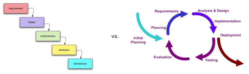
The concurrent engineering principle has mostly altered the conventional sequential design strategy to a great extent. The linear fashion of sequential design philosophy is now related to the integrated development method of concurrent engineering. The main fault with the sequential design method is that if something goes wrong the process must be altered heavily which impacts the economy of the product development. Whereas the concurrent engineering methodology smoothly resolves the problem and encourages positive changes that allow an evolutionary design approach. The difference between the two approaches can easily be recognized from the Wikipedia image attached in Fig. 1 below.
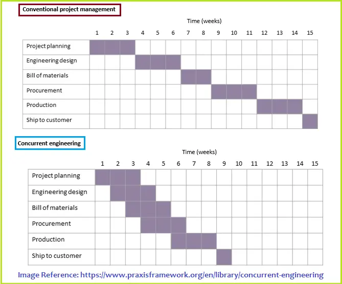
The image in Fig. 2 below is self-explanatory to understand how the concurrent engineering design process can effectively save time with respect to the conventional sequential engineering approach:
Product development process using Concurrent Engineering
To create a timely product with the highest quality and lowest cost, concurrent engineering methodologies provide a very important concept. The basic concurrent engineering product/service development process consists of the following four main phases:
- Market Investigation
- Product Design Specification
- Conceptual Design
- Concept Generation
- Concept Evaluation
- Concept Development
- Detail Design
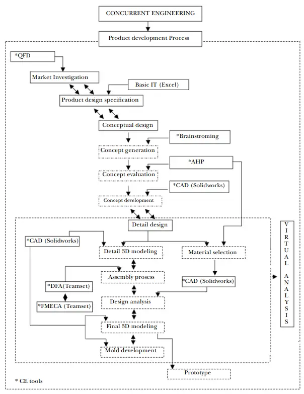
The typical concurrent engineering processes using concurrent engineering is clearly explained by A. Hambali, S.M. Sapuan, N. Ismail, Y. Nukman, and M.S. Abdul Karim in their paper “The Important Role of Concurrent Engineering in
Product Development Process” as shown in Fig. 3 below
Challenges of Concurrent Engineering
The main challenges that arise in the concurrent engineering philosophy are:
- dependency on efficient communication between team members.
- implementation of early design reviews.
- software compatibility.
- efficient exchange of computer models/design information.
- organizing and managing project teams effectively.
- training people on how to perform concurrent design effectively.
Examples of Concurrent Engineering
Even though originated in Japan, various companies around the world have adopted the philosophies of Concurrent Engineering. A few such organizations that glorify the examples of concurrent engineering are:
- NASA
- ASI
- Schlumberger
- STV Incorporated
- Boeing
- Harley Davidson
- CNES
- ASML, etc