Piping Engineers must have come across terms like Flange Pressure Temperature Rating, Flange Rating, P-T rating, Flange Pressure rating, Pressure rating or Flange Class, etc. All these terms are related to a very important and frequently used Piping component called Flanges. This article will briefly explain such terms with respect to ASME B16.5 and ASME B16.47 for simplification in understanding.
Flanges are designed and manufactured based on American codes ASME B16.5 and ASME B16.47. While the former i.e ASME B16.5 covers the flanges from NPS 1/2 inches to NPS 24 inches, the latter, ASME B16.47 covers the flanges from NPS 26 inches to NPS 60 inches.
What is the Pressure-Temperature rating for Flanges?
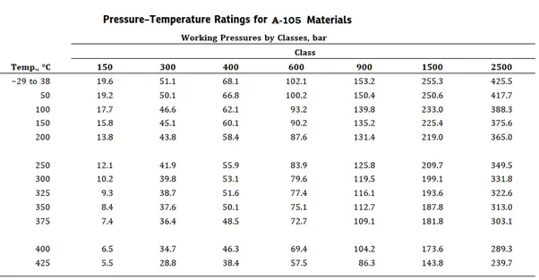
Pressure–temperature ratings are the maximum allowable working gauge pressures at the temperatures for the applicable material and class designation. So Pressure and Temperature Rating tables of ASME codes provide a limit of Maximum working pressure at which the flange can be subjected for a longer duration at a specified temperature. For intermediate temperatures, linear interpolation can be done. Refer to Fig. 1 showing a sample pressure-temperature rating table from B16.5.

From the above table, the following important points can be noted:
- With an increase in temperature, the pressure-withstanding capability of the same material decreases.
- With an increase in pressure class rating, pressure capability increases.
- With a change in flange material pressure-temperature table and pressure withstanding capability changes at the same pressure class rating.
The temperature shown for a corresponding pressure-temperature rating class table is normally the temperature of the pressure-containing shell of the valve or flange.
Types of Flange Pressure-Temperature ratings
Normally two types of pressure-temperature ratings are used for piping/pipeline flanges. They are
- Pressure-Temperature rating for API flanges and
- Pressure-Temperature rating for ASME or ANSI Flanges.
For oil drilling and wellhead system applications, API flanges are used which are based on the API 6A standard. The pressure-temperature rating for API flanges ranges from 2000 psi to 20,000 psi.
For all other applications, ASME or ANSI flanges are used which are based on ASME B16.5 for sizes up to 24″ and ASME B16.47 for larger sizes.
What are Flange Rating and Flange Classes?
ASME/ANSI B16.5 standard provides seven flange pressure ratings: 150, 300, 400, 600, 900, 1500, and 2500. They are also known as Flange Class and denoted by Class, followed by anyone of the above-mentioned dimensionless numbers. They are also referred to as “Pound Rating” or Pressure Class Rating.
A few important features of flange classes are:

- The higher the flange rating, the higher the pressure it can withstand at temperatures.
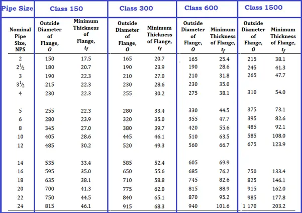
- Flanges with higher ratings have more thickness (Refer to Fig. 2) and more weight and are stronger as compared to flanges with lower ratings.
- With the change in pressure rating class, flange dimensions vary, and hence, the flange of one pressure class may not fit with its higher or lower class flange.
- With the increase in pressure rating, the number of bolts increases which increases the bolt area. The increase in bolt area reduces flange leakage tendency by increasing force and moment-carrying capability.
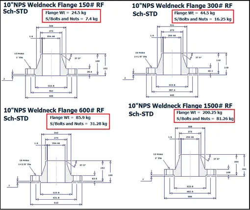
Refer to the following image (Fig. 3), produced from Pipe Data Pro to show you an idea of dimensional and weight differences for a 10-inch NPS Sch STD.

Sample Calculation for determining Flange Rating
Let’s Assume We have to select an ASME B16.5 flange for a Carbon Steel pipe carrying fluid at 300 Deg C design temperature and 50 bar design pressure. To select the proper flange Refer to figure 1 which shows the pressure-temperature rating for CS (A-105) material.
- From the Figure, We can see that the Maximum Pressure that the A-105 flange with 150 pressure class can withstand at 300 Deg C Temperature is 10.2 bar which is lower than our design pressure (50 bar). So not suitable.
- Next, we will move to the next higher class i. e, pressure class 300. Here the maximum pressure capability is 39.8 bar which is also less than 50 bar. So rating class 300 is also not suitable.
- Now e will move to the next higher class i. e, pressure class 400. Here the maximum pressure capability is 53.1 bar which is more than our design pressure.
- So Selected flange class is 400.
Calculating Rated Flange Pressure
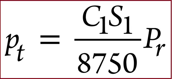
As mentioned in Appendix A of B 16.5, the pressure-temperature ratings for Class 300 and higher can be derived by the following equation:

Here,
- C1 = 10 when S1 is expressed in MPa units and the resultant pt will be in bar units (C1 = 1 when S1 is expressed in psi units and the resultant pt will be in psi units)
- Pr = pressure rating class index. For all designations, Class 300 and above, Pr is equal to the class designation (e.g., for Class 300, Pr = 300).
- pt = rated working pressure, bar (psi), for the specified material at temperature T
- S1 = selected stress, MPa (psi) for the specified material at temperature T.
Now if we apply the above equation for the above-mentioned sample problem, we will get the following output.
Here,
- Pt=50 bar
- S1=133 Mpa
- C1=10
Hence Pr=(8750*50)/10*133= 329.
As the calculated Rated working pressure is more than 300, we will select class 400 for the flange.
Few more related useful resources for you..
Guidelines for Selection of Various Types of Flanges
Methods for Checking Flange Leakage
Flange Insulating Gasket Kits for Industrial Application
Recorded Webinar on Detailed Flange Analysis with CAESAR II using EN-1591
Pressure Temperature Rating and Flange rating of ASME Flanges
Methods for flange leakage checking by Pressure Equivalent Method using Caesar II
PROCEDURE FOR FLANGE-BOLT TIGHTENING OF VARIOUS SIZES OF FLANGES
Flange Leakage Evaluation based on NC 3658.3 Method method using Caesar II
Few points on Gaskets for leak Proof Flanged joints
Consideration of Flanged Bend while modeling in Caesar II
Flange Leakage checking in Caesar II using ASME Section VIII method
Functions of Gaskets for leak-proof Flanged joints

hi
good blog very informative
wana know from where 8750 comes in formula as well as need the table for the values s1=133Mpa for c1=10
IN ASME B 16.5 and 16.34 they have written as 400 Cl. Flange rarely used. Is there any reason?