My last two articles on flange leakage explain the basic theory behind flange leakage checking and methods for performing flange leakage checking using the pressure equivalent method. In this article, I will explain the steps taken to perform a flange leakage check using Caesar II by the ASME Sec VIII method.
Background of ASME Sec VIII Flange Leakage Checking
ASME Sec VIII flange leakage method is performed when the flange analysis using the pressure equivalent method shows failure in Caesar II. The pressure equivalent method is believed to be highly conservative and does not provide the actual results. In most situations, the pressure equivalent flange leakage checking shows failure even with very less axial force and bending moments. It is, therefore, a standard engineering practice to perform the ASME Sec VIII method for those flanges where the pressure equivalent method shows failure.
ASME Sec VIII flange leakage checking method is widely accepted in industries and frequently used to qualify the flanges where the pressure equivalent method shows a failure.
Inputs for ASME Sec VIII Flange Leakage Checking
The following codes and standards are required for data input in the Caesar II flange leakage spreadsheet while performing the ASME Sec VIII method.
- ASME B 16.5/ASME B 16.47- Latest Edition (For Flange Data)
- ASME B 16.20- Latest Edition (For Gasket Data)
- Piping Material Specification (For Flange, Bolt, and Gasket Materials and types)
Steps for ASME Sec VIII Flange Checking Method in Caesar II
The basic steps involved in performing ASME Sec VIII flange leakage checking in Caesar II are mentioned below:
Creating the Flange Analysis File
1. After performing static analysis click “Analysis” and then click “Flanges” in CAESAR II as shown below.
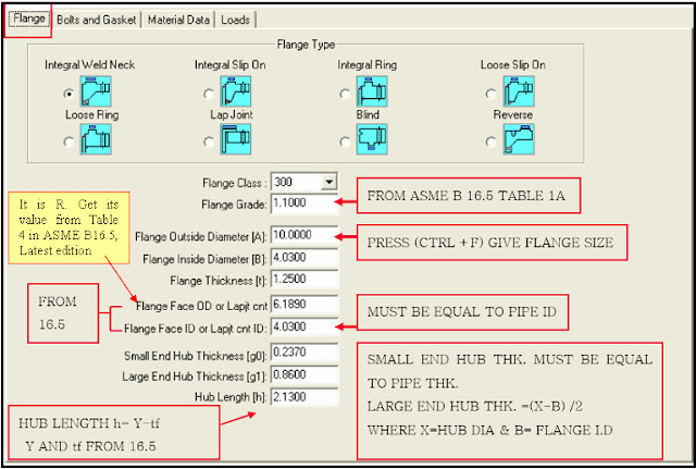
2. Provide a file name and select the proper Flange Type in the section as mentioned in the PMS. Input the flange parameters in the consistent unit as per the used UNIT FIL as shown below:
Entering Flange Parameters
3. Press the key “Ctrl+F” to select the concerning Size and Rating. Few data will automatically be filled from the Caesar II database. However, it is good practice to confirm the data from the governing code.
4. Flange Class is the flange pressure rating and is required for checking the P-T Rating of Equivalent Pressure.
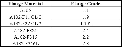
5. Flange Grade: Select Material Group No. as per ASME B 16.5 Table 1A list of material specifications. The following table can be used as a reference:
6. Refer to the applicable flange code ASME 16.5 or ASME B 16.47 and update automatically filled flange data. Take special care while inputting for ‘Small End Hub Thickness’& ‘Large End Hub Thickness’. ‘Small End Hub Thickness ’ must be equal to the Pipe Thickness. Large End Hub Thickness must be equal to (X-B) where X is Hub Diameter and B Flange ID.
Enter hub Length h=(Y-tf) where Y is length through Hub and tf is flange thickness.
Inputting Bolt and Gasket Data
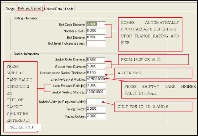
7. Now enter the Bolts and gasket parameters. Take parameters from ASME B 16.20 or ASME B 16.21 as shown below:
8. Check the Bolt Circle Diameter, Number of Bolts, and Bolt Diameter, suggested by CAESAR II in reference to ASME B 16.47, 16.5.
9. Correctly input for Gasket information in conjunction with ASME B 16.20 or 16.21 as applicable.
10. For Effective Gasket Modulus, press Shift+? Key and then follow “High End” in the Help statement. Leak Pressure Ratio m, Gasket Seating Stress y shall be in accordance with ASME SECTION VIII Div.1. Values for Caesar II help can be taken by pressing Shift+? or by pressing the F1 key keeping the cursor on the relevant box. Click here to know more about leak pressure ratio m and gasket seating stress y.
11. For Nubbin Width on the right side, Leave blank for Welding Neck Type and input Ring joint width as per the ring no. as described on ASME B 16.20 Table 3 TYPE R RING GASKET DIMENSIONS AND TOLERANCES for ring type joint.
12. Facing Sketch/ Facing Column can be inputted as follows mentioned below:
Entering Material Data
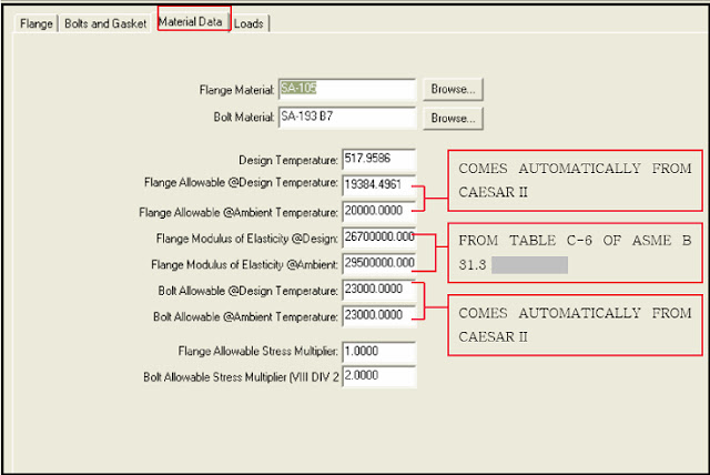
13. Now input the material data as shown below:
14. Select the material of the Flange and bolt, and the Input design temperature.
15. Flange Allowable & Bolt Allowable at design and ambient temp can be taken from the CAESAR II database for particular flange and bolt material.
16. Flange Modulus of Elasticity shall be taken from table C-6 of ASME B-31.3.which is given in millions of psi to convert it to the consistent unit.
Inputting Pressure and Load Data
17. Use 1.0 for Flange Allowable Stress Multiplier and 2.0 for Bolt Allowable Stress Multiplier. Use project-specific data if available.
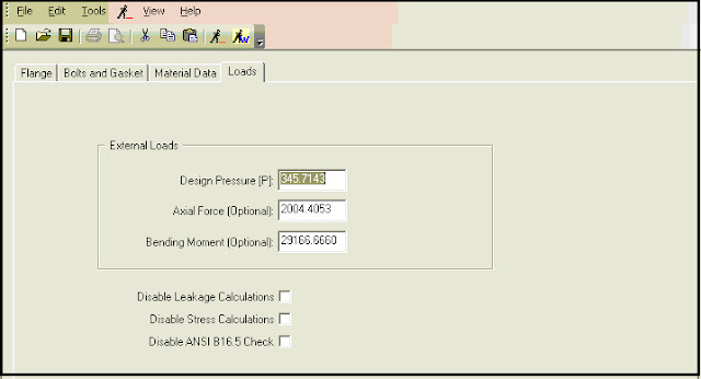
18. Now Input Design Pressure, Axial Force, and Bending Moment from Static analysis of the Caesar file as shown below:
Performing Flange Leakage Analysis and Reviewing Results
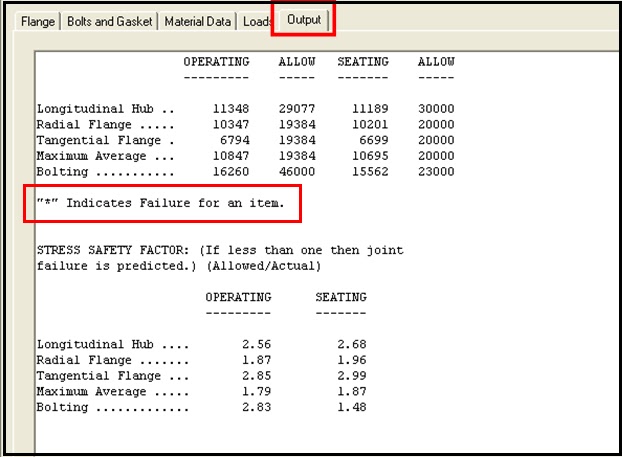
19. Now run the analysis to study the output results. Normally If the safety factor is less than one then joint failure is predicted and in output, this is shown by a * mark.
20. If the output result shows failure then try to reduce the bending moment or axial force and reanalyze. If that is not possible check if the flange rating can be increased.
Sometimes, the flanges are seen to be failing in seating stresses. In such a scenario, try to get actual gasket seating stress data from the vendor and enter it into the spreadsheet. Normally with reduced gasket seating stress value seating failure can be avoided.
Click here to find out the Flange leakage checking methodology based on NC 3658.3 Method



I am performing flange leakage analysis check for various flanges on a project, and most of them failed the check. These are above grade flanges in a gas pipeline facility (main line valves, pig launchers). I am not considering external pressures or moments. Can you help with troubleshooting? Thank you, Ada.
A great article, thanks very much
Can you please clarify how to get “Uncompressed gasket thickness” ?
Uncompressed gasket thickness is available in ASME B 16.20. Normally it is 4.45 mm. Otherwise the same can be specified in piping material specification.
when i use ring type gasket, where is the Uncompressed gasket thickness?
I have to perform flange leakage analysis of flange having following specifications:
API 6A FLANGE
RATING-10000#
MATERIAL-ASTM 694-F65
In CAESAR software data base API flange option is not available but only ASME and EN codes are there. Now, to perform the analysis for my above mentioned flange what procedure I have to follow in CAESAR.
Your urgent response will be highly appreciated.
Regards,
First perform equivalent pressure method. If it fails then proceed with NC method.
Well i get the axial force (i.e in the direction of pipe)eg. be it in X direction, how do i get the bending moment. since it is in two directions i.e in Y and Z . Should i take the higher of the two values or should i take its square root sum ?
based on these two method Pressure Equivalent Method vs ASME Sec Viii, which one is more conservative.
Hi,
really interesting article; often i have to perform leakage test in caesar2 environment and often I find more problems at seating than in operative conditions. The main reason is the gasket seating “y” because somtimes client ask to insert the seating load applied on tie rods acc. to PCC1 (so resulting in really higher values of “y” than the values listed in the ASME VIII div1 App.2) and to apply the verification in ASME VIII Div1 App.2 resulting in overstress in both bolt and flange itself…have you ever found a problem like this?
Regards
Hi,
While performing analysis as per ASME B 31.3, the stress values on multiple flange pairs defined in the piping system come to zero in the code compliance report. The piping, flanges and fittings specs have been appropriately defied. Please advise .
Related to this issue
I want to know the limitation for installing insulation on pipe flange fittings and valves for hot and cold gas and liquid pipes