The upcoming CAESAR II release will deliver a number of significant new and extended capabilities in response to current market requirements, as well as direct feedback from the growing CAESAR II user community. Currently, they are running their beta testing for the new version of the software. From that beta software, We come to know that The following changes will have been made to CAESAR II 2019, Version 11.00
Piping Input:
- Added the CAESAR II Determines option to Allowable Stress Indicator for the B31.8 code, similar to the existing implementation for B31.4. CAESAR II Determines specifies that the software selects the stress equations based on the calculated axial load in the piping system.
- Added node name and node number formatting options to Options > Node Numbers. You can now display names and numbers with the same formatting available for Options > Node Name in the Static Output Processor.
- Updated and renamed the Global Coordinates and Global commands to View/Set Coordinates. The new Global Coordinates dialog box displays a grid view of nodes and coordinates for all disconnected elements, and you can edit the values.
- Updated the Coordinates and Elements lists to support the new View/Set Coordinates command. The start (From) node displays in the Node column of the Coordinates list. Right-click > View/Set Coordinates displays on the Coordinates list. Disconnected element rows highlight in green in both lists.
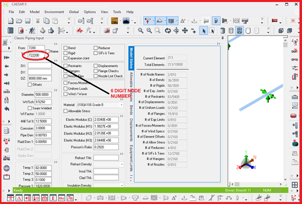
- Extended the range for node numbers. A node number previously had a maximum value of 32,000. It now has a maximum value of 8,000,000. Refer Fig. 1
- Improved the efficiency of processing disconnected segments to function with the extended node number range.
- Improved the behavior of node names. The same node name now displays on all elements sharing the same node.
- Increased the maximum length of node names from 10 to 25 characters.
- Increased the number of Uniform Loads from three to nine vectors
- Added a restraint legend which allows you to visually identify and edit restraint gap values.
- Added the Rigid Type option to the Rigids auxiliary data tab. When you define a rigid type, the software graphically displays that type for the element in the model view.
- For the ISO-14692 2005 code, allowed editing of the Pressure SIF box on the SIFs/Tees auxiliary tab. You can now change the value in both boxes from the default value of 1.3.
- Adjusted the density for material (191) A335 P91.
- Added the ability to create multiple toolbar and command profiles. You can switch between profiles as needed. Delivered a new functional profile as the default profile.

Load Case Editor:
- Added import of a properly formatted Excel .xlsx file into the Static Analysis – Load Case Editor. The software also provides an example template file, LCE_Template.xltx, in the C:\\ProgramData\Intergraph CAS\CAESAR II\11.00\System\templates folder.
- Added export of an Excel .xlsx file from the Static Analysis – Load Case Editor.
- Added an Exclude option that allows you to easily remove a selected load case from the static analysis.
- Updated the Static Analysis – Load Case Editor for the DNV 2017 piping code, including a new limit state (LMST) stress type for combined load cases, and a new Limit State Load Type field for non-combined load cases and non-LMST combined loads.
- For ASME NC-3658.3 flanged joint calculations, changed the hydrotest (HYD) load cases to use the same allowable as the occasional (OCC) load cases.
Piping, Equipment, and Environmental Codes:
- Added support for ASCE 7-2016 wind and seismic loads.
- Added support for the China GB 50009-2012 wind code.
- Added support for the ISO 14692 2017 piping code.
- Added support for the DNV 2017 (DNVGL-ST-F101) piping code, including a new DNV/Offshore tab for Special Execution Parameters.
- Updated the CODETI code to the November 2016 edition, and corrected CODETI code stress equations in the Quick Reference Guide.
- Updated the KHK Seismic Design Guideline for the High-Pressure Gas Facilities to the 2012 edition.
- Updated the ASME B31.1 code to the July 2018 edition.
- Updated the BS EN 13480 code to the June 2017 edition.
- Updated the Errors and Warnings grid to perform more like Microsoft Excel. The grid supports selection and copy of grid rows between the grid and Excel.
- For the Seismic Wizard, changed the default value for the ASCE 7 Response Factor R from 12 to 3.5 to comply with ASME B31.
- Added support for displaying all component stress values (hoop, allowable, SIF) in reports instead of only the highest component stress.
Material and Content:
- Updated the Material Database Editor grid to support copy, cut, paste, and delete of cells and rows within the grid and between the grid and Excel.
- Updated the hanger table for LISEGA.
Configuration:
- Updated B31.4 and B31.8 codes to function similarly for non-default configuration settings and combination load cases.
Equipment:
- Expanded the redesigned Equipment Manager to include API 617, API 560, API 661, NEMA SM23, and HEI Standard equipment modules into the single Equipment Manager window. (API 610 equipment was moved into the Equipment Manager in the previous release.) Changes include updates to calculations and updates to reports to meet Equipment Manager standards.
- Added several usability improvements. Node Number is now optional. Most recently used files are now available. Status and warnings for the equipment input display before analysis and in the status pane and in the output report after analysis completes.
Analysis:
- For static analysis, clarified the usage of the wind load reduction factor for ASCE 7. You must explicitly apply this factor to the wind load component in a wind load case.
- For dynamic analysis, corrected the determination of the pressure stiffening effect on bends by excluding hydro pressure.
User Interface:
- Added shortcut keys that are used consistently throughout the software.
- Improved the File tab options on the main window ribbon, including improved existing options, and new folder and help access.
- Removed the secondary menu from the main window. All commands are on the main window ribbon.
- Added a new Layout menu to the main window ribbon. The menu provides theme, language, and icon size options and allows you to reset to the default layout.
- Changed the default look of the software to a new light gray Light theme. The existing dark gray Dark theme is available on the Layout menu.
- Changed some graphics defaults to better match the most commonly-used settings. New defaults include: Default Operator (Select), Hide Overlapping Text (on), Text Options (12 pt. by default), and Bottom and Top background colors (white).
- Updated the File > About window to improve usability and appearance. Also updated the Help and About icons to provide a look consistent with other interface improvements.
- Updated the Help tab to eliminate unnecessary commands, better organize the remaining commands, and provide a new help search function.
Isometrics:
- Added the option to create .pdf files when you create .dwg files using Create Isometric Drawings. The software also saves .dwg drawing files and .pdf files in the same folder as the piping model.
- Updated Generate Stress Isometrics to Personal ISOGEN 2016 (10.0.0.1) and to I-Configure 2016 (06.00.00.11).
- Improved the creation of isometric drawings for models containing dummy legs.
- Improved usability of stress isometric annotations. When you select a Restraint/Hanger Types or SIF/Fitting Data input feature, the software also selects the corresponding Node Numbers feature.
Underground Pipe Modeler:
- Updated the Underground Pipe Modeler grid to support copy and paste of rows within the grid and between the grid and Excel.
Output Processor:
- Added access to the Data Export Wizard from the Static Output Processor.
- Added a Maximize/Restore button to report windows for static reports. The software also saves the most recent window size and uses it when you open the next report window.
- Changed standard reports to more consistently report component stresses. Created a standard Stresses report, a new Stresses (Multiple Code/Allow.) report for transportation and offshore codes. Changed the Stresses Extended report to the Stresses Extended (Legacy) report. Removed the previous Stress and Code Compliance reports. Renamed the Code Compliance Extended report to Code Compliance.
Configuration:
- Updated B31.4 and B31.8 codes to function similarly for non-default configuration settings and combination load cases.
Material and Content:
- Updated the Material Database Editor grid to support copy, cut, paste, and delete of cells and rows within the grid and between the grid and Excel.
- Updated the hanger table for LISEGA.
External Interfaces:
- Improved Import PCF to allow you to import a large number of files.
- Added an interface for BOSfluids file import, using a dialog box similar to the other hydraulic module interfaces. Also added an option to directly open Dynamic Analysis after import completes.
- Updated the neutral file format so that line numbers, line color, line visibility, and bend overlay thickness now import and export.
- Improved the Data Export Wizard to allow multiple output report exports in one session. Improved defaults of the Input and Output Files window and changed the default output file format to .accdb (Microsoft Office 2007 and later Access database) to improve usability.
Documentation/Help:
- Converted help to a new help viewer with an improved interface and search, and changed the format of units to eliminate display issues.
- Updated thermal coefficient of expansion topics to specify the length and temperature units of the model.
- Added more details and equations to the CAESAR II Determines option of Allowable Stress Indicator for finding the pipe restrained/unrestrained status in the B31.4 code.
- Clarified usage of the Free Measure option of Distance. The option should only be used in 2D views.
- Added a shortcut key overview to the Quick Reference Guide.
- Added information on editing ASCII text files.
- Clarified descriptions of numeric calculations in delta and length fields of Classic Piping Input.
- Added descriptions for Multiple Load Case Hanger Design Options in the Hangers auxiliary panel, the Hanger Design Control Data dialog box of Classic Piping Input, and the Technical Discussions section.
- Added a note to Type for SIFs & Tees that describes the importance of properly defining tees to avoid overly conservative SIF values.
Learn the changes in the different versions of Caesar II software:
Caesar II Version 12 vs Caesar II Version 11
Major features of CAESAR II-2019, Version 11.00
Added Features of CAESAR II 2018, Version 10.00
What’s New in CAESAR II, 2016 (Version 8.0)
Practical changes in Caesar II version 7.0 (2014) with respect to its earlier version.


the underground pipe modeller gives an error that the restraints are very much, it breaks the model into 17553 nodes but after that gives an error. is there any specified limitation on restraints added by UGPM. like there is a limitation for the nodes which amounts to 8000000.