When it comes to structural engineering and construction, the choice of beam design plays a crucial role in ensuring the integrity and safety of a structure. Among the most common types of beams used are H-beams and I-beams. While they may seem similar at first glance, each type has its own set of characteristics, advantages, and applications.
H-beam or I-beam
Both H-beam and I-beams are structural steel materials used widely in the construction industry by civil engineering professionals. By a novice, both these members may seem to be similar. The horizontal elements of the I and H beam are known as flanges, while the vertical element is called as the “web”. The web resists shear forces, and the flanges are designed to resist most of the bending moment that the beam experiences.
In general, The design of both I-beam and H-beam is governed by any of the following criteria:
- deflection: The target criteria should be to minimize deformation
- vibration: the stiffness and mass should be decided based on vibration tendency.
- bending failure by yielding
- bending failure by lateral torsional buckling
- bending failure by local buckling
- local yield due to the high magnitude of concentrated loads.
- shear failure
- buckling or yielding of components
However, both are quite different from one another. In this article, We will explore the main differences between I-beam and H-beam.
What is an H-beam?
H-beam is an incredibly strong structural steel member. As the cross-section of this beam resembles the capital letter “H”, it is known as H-beam. Fig. 1 shows a typical example of an H-beam. The main characteristics of H-beams are:
- Shape: The cross-section is symmetrical, providing uniform strength in all directions.
- Dimensions: Available in various sizes, typically larger than I-beams.
- Weight: Generally heavier than I-beams, which can affect transportation and handling.
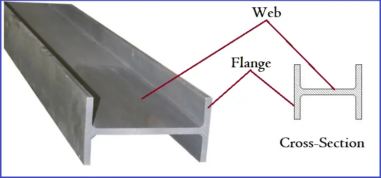
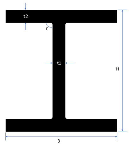
H-beams have an equal thickness in the two parallel flanges without any taper on the inside surface. Depending on the height and flange width; H-beams are classified into three categories. They are
- Wide Flange Series H-beam
- Medium Flange Series H-beam and
- Narrow Flange Series H-beam.
H-beam Size Chart
Typical H-beam size and weight chart is provided in the table below: Refer to Fig. 2
|
H beam size and weight chart: Wide Flange Series (HW) |
||||||||
|
Grade |
Size of the Section (in mm) |
Cross-Sectional Area |
Weight |
Member Designation |
||||
|
|
H |
B |
t1 |
t2 |
r |
cm2 |
kg/m |
|
|
100 X 100 |
100 |
100 |
6 |
8 |
10 |
21.9 |
17.19 |
100x100x6x8 |
|
125 X 125 |
125 |
125 |
6.5 |
9 |
10 |
30.31 |
23.79 |
125x125x6.5×9 |
|
150 X 150 |
150 |
150 |
7 |
10 |
13 |
40.55 |
31.83 |
150x150x7x10 |
|
175 X 175 |
175 |
175 |
7.5 |
11 |
13 |
51.43 |
40.37 |
175x175x7.5×11 |
|
200 X 200 |
200 |
200 |
8 |
12 |
16 |
64.28 |
50.46 |
200x200x8x12 |
|
200 |
204 |
12 |
12 |
16 |
72.28 |
56.74 |
200x204x12x12 |
|
|
250 X 250 |
250 |
250 |
9 |
14 |
16 |
92.18 |
72.36 |
250x250x9x14 |
|
250 |
255 |
14 |
14 |
16 |
104.68 |
82.17 |
250x255x14x14 |
|
|
H beam size and weight chart: Medium Flange Series (HM) |
||||||||
|
150 X 100 |
148 |
100 |
6 |
9 |
13 |
27.25 |
21.39 |
148x100x6x9 |
|
200 X 150 |
194 |
150 |
6 |
9 |
16 |
39.76 |
31.21 |
194x150x6x9 |
|
250 X 175 |
244 |
175 |
7 |
11 |
16 |
56.24 |
44.15 |
244x175x7x11 |
|
300 X 200 |
294 |
200 |
8 |
12 |
20 |
73.03 |
57.33 |
294x200x8x12 |
|
H beam size and weight chart: Narrow Flange Series (HN) |
||||||||
|
175 X 90 |
175 |
90 |
5 |
8 |
10 |
23.21 |
18.22 |
175x90x5x8 |
|
200 X 100 |
198 |
99 |
4.5 |
7 |
13 |
23.59 |
18.52 |
198x99x4.5×7 |
|
200 |
100 |
5.5 |
8 |
13 |
27.57 |
21.64 |
200x100x5.5×8 |
|
|
250 X 125 |
248 |
124 |
5 |
8 |
13 |
32.89 |
25.82 |
248x124x5x8 |
|
250 |
125 |
6 |
9 |
13 |
37.87 |
29.73 |
250x125x6x9 |
|
What is an I-beam?
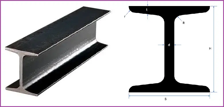
I-beams are also structural steel members but their cross sections resemble the capital letter “I”. Consisting of two flanges and one web, an I-beam has a slope on the inner surface of the flanges. Depending on the use, I-beam sections are available in a range of weights, flange widths, sections, depths, and web thicknesses. The major characteristics of I-beams are:
- Shape: The cross-section is also symmetrical but generally has narrower flanges compared to H-beams.
- Dimensions: Available in a range of sizes, often lighter than H-beams.
- Weight: Typically less weight than H-beams, making them easier to handle in certain applications.
Fig. 3 below shows a typical example of I-beams.
I-beam Size Chart
I-beam size charts for some common structural sections are provided below:
|
Designation |
Dimensions |
|||||
|
Depth
|
Width
|
Web Thickness
|
Cross-Sectional Area |
Weight |
||
|
UB 127 x 76 x 13 |
127 |
76 |
4 |
16.5 |
13 |
|
|
UB 152 x 89 x 16 |
152.4 |
88.7 |
4.5 |
20.3 |
16 |
|
|
UB 178 x 102 x 19 |
177.8 |
101.2 |
4.8 |
24.3 |
19 |
|
|
UB 203 x 102 x 23 |
203.2 |
101.8 |
5.4 |
29.4 |
23.1 |
|
|
UB 203 x 133 x 25 |
203.2 |
133.2 |
5.7 |
32 |
25.1 |
|
|
UB 203 x 133 x 30 |
206.8 |
133.9 |
6.4 |
38.2 |
30 |
|
|
UB 254 x 102 x 22 |
254 |
101.6 |
5.7 |
28 |
22 |
|
|
UB 254 x 102 x 25 |
257.2 |
101.9 |
6 |
32 |
25.2 |
|
|
UB 254 x 102 x 28 |
260.4 |
102.2 |
6.3 |
36.1 |
28.3 |
|
|
UB 254 x 146 x 31 |
251.4 |
146.1 |
6 |
39.7 |
31.1 |
|
|
UB 254 x 146 x 37 |
256 |
146.4 |
6.3 |
47.2 |
37 |
|
|
UB 254 x 146 x 43 |
259.6 |
147.3 |
7.2 |
54.8 |
43 |
|
|
UB 305 x 102 x 25 |
305.1 |
101.6 |
5.8 |
31.6 |
24.8 |
|
|
UB 305 x 102 x 28 |
308.7 |
101.8 |
6 |
35.9 |
28.2 |
|
|
UB 305 x 102 x 33 |
312.7 |
102.4 |
6.6 |
41.8 |
32.8 |
|
|
UB 305 x 127 x 37 |
304.4 |
123.4 |
7.1 |
47.2 |
37 |
|
|
UB 305 x 127 x 42 |
307.2 |
124.3 |
8 |
53.4 |
41.9 |
|
|
UB 305 x 127 x 48 |
311 |
125.3 |
9 |
61.2 |
48.1 |
|
|
UB 305 x 165 x 40 |
303.4 |
165 |
6 |
51.3 |
40.3 |
|
|
UB 305 x 165 x 46 |
306.6 |
165.7 |
6.7 |
58.8 |
46.1 |
|
|
UB 305 x 165 x 54 |
310.4 |
166.9 |
7.9 |
68.8 |
54 |
|
|
UB 356 x 127 x 33 |
349 |
125.4 |
6 |
42.1 |
33.1 |
|
|
UB 356 x 127 x 39 |
353.4 |
126 |
6.6 |
49.8 |
39.1 |
|
|
UB 356 x 171 x 45 |
351.4 |
171.1 |
7 |
57.3 |
45 |
|
|
UB 356 x 171 x 51 |
355 |
171.5 |
7.4 |
64.9 |
51 |
|
|
UB 356 x 171 x 57 |
358 |
172.2 |
8.1 |
72.6 |
57 |
|
|
UB 356 x 171 x 67 |
363.4 |
173.2 |
9.1 |
85.5 |
67.1 |
|
|
UB 406 x 140 x 39 |
398 |
141.8 |
6.4 |
49.7 |
39 |
|
|
UB 406 x 140 x 46 |
403.2 |
142.2 |
6.8 |
58.6 |
46 |
|
|
UB 406 x 178 x 54 |
402.6 |
177.7 |
7.7 |
69 |
54.1 |
|
|
UB 406 x 178 x 60 |
406.4 |
177.9 |
7.9 |
76.5 |
60.1 |
|
|
UB 406 x 178 x 67 |
409.4 |
178.8 |
8.8 |
85.5 |
67.1 |
|
|
UB 406 x 178 x 74 |
412.8 |
179.5 |
9.5 |
94.5 |
74.2 |
|
|
UB 457 x 152 x 52 |
449.8 |
152.4 |
7.6 |
66.6 |
52.3 |
|
|
UB 457 x 152 x 60 |
454.6 |
152.9 |
8.1 |
76.2 |
59.8 |
|
|
UB 457 x 152 x 67 |
458 |
153.8 |
9 |
85.6 |
67.2 |
|
|
UB 457 x 152 x 74 |
462 |
154.4 |
9.6 |
94.5 |
74.2 |
|
|
UB 457 x 152 x 82 |
465.8 |
155.3 |
10.5 |
104.5 |
82.1 |
|
|
UB 457 x 191 x 67 |
453.4 |
189.9 |
8.5 |
85.5 |
67.1 |
|
|
UB 457 x 191 x 74 |
457 |
190.4 |
9 |
94.6 |
74.3 |
|
|
UB 457 x 191 x 82 |
460 |
191.3 |
9.9 |
104.5 |
82 |
|
|
UB 457 x 191 x 89 |
463.4 |
191.9 |
10.5 |
113.8 |
89.3 |
|
|
UB 457 x 191 x 98 |
467.2 |
192.8 |
11.4 |
125.3 |
98.3 |
|
Common Beam Standards
Common standards that govern the shape and tolerances of structural beam sections are:
- AISC Manual
- IS 808
- ASTM A6,
- DIN 1025
- BS 4-1
- AS/NZS 3679.1
- EN 10024
- EN 10034
- EN 10162
H-beam vs I-beam: Difference between H-beam and I-beam
H-beam vs I-beam: Dimensions and Weight
- An H-beam has a significantly thicker web than an I-beam.
- An I-beam normally has a slope of 1:6 to 1: 10 in the flange whereas the H-beam has a uniform flange.
- An H-beam is heavier as compared to an I-beam.
- The distance of the flanges can be widened as per requirement for an H-beam section but the same is fixed for the I-beam.
- The moment of inertia is different for both beams.
- In an I-beam, the size of the web is greater than the size of the flange whereas in an H-beam it may not be true.
H-beam vs I-beam: Mechanical Properties
- The cross-section of the I-beam is poor against twisting as compared to H-beam.
- In general, H-beams are more rigid and can carry more load as compared to I-beams.
- H-beams are used as columns while I-beams are used as beams.
H-beam vs I-beam: Manufacturing
- An I-beam is manufactured as a single piece throughout, but an H-beam is normally manufactured by welding 3 pieces of metal.
- An H-beam can be produced to any desired size and height whereas the production of I-beams is limited by the milling machine capacity.
For easy comparison, the differences between H-beam and I-beam are provided in the following table.
| Feature | H-Beam | I-Beam |
|---|---|---|
| Cross-Section Shape | Resembles the letter “H” | Resembles the letter “I” |
| Flange Width | Wider flanges than I-beams. | Narrower flanges than H-beams. |
| Web Depth | H-beams have deeper web. | I-beams have shallower web. |
| Weight | Generally heavier than I-beams. | Typically lighter than H-beams. |
| Load-Bearing Capacity | H-beams possess higher load capacity. | I-beams have lower load capacity. |
| Stability | H-beams have better lateral stability than I-beams. | I-beams are more susceptible to buckling. |
| Applications | Major application of H-beams are found in bridges, high-rise buildings, heavy machinery, etc. | I-beams are widely used in residential, commercial, light industrial, etc. |
| Cost | H-beams are generally more expensive. | I-beams are typically less expensive. |
| Handling | H-beams require more robust lifting equipment. So, they are difficult to handle. | I-beams are comparatively easier to handle and transport. |
| Versatility | They are suitable for heavy-duty applications. | I-beams are the best for lighter loads. |
| Deflection | H-beams experience less deflection under load. | Comparatively more deflection under heavy loads. |
| Connection Types | Often welded for continuous support | Can be bolted or welded |
This table summarizes the key differences, making it easy to compare H-beams and I-beams at a glance.
In conclusion, both H-beams and I-beams have unique properties that make them suitable for different applications in construction and engineering. H-beams offer higher load-bearing capacity and stability, making them ideal for heavy-duty applications, while I-beams provide a lightweight, cost-effective solution for lighter loads. The choice between the two should be based on a thorough understanding of the specific requirements of a project, including load conditions, cost considerations, and structural integrity.
Frequently Asked Questions: H-beam and I-beam
1. What is the primary difference between H-beams and I-beams?
The primary difference lies in their cross-sectional shapes. H-beams have wider flanges and a deeper web, while I-beams have narrower flanges and a shallower web, affecting their load-bearing capacities and applications.
2. Which beam is stronger: H-beam or I-beam?
H-beams generally have a higher load-bearing capacity due to their wider flanges and deeper web, making them suitable for heavy-duty applications. I-beams are lighter and more suited for lighter loads.
3. In what applications are H-beams typically used?
H-beams are commonly used in bridges, high-rise buildings, and heavy machinery support where high strength and stability are required.
4. Where are I-beams commonly found?
I-beams are typically used in residential construction, commercial buildings, and lighter industrial applications, where the loads are lower.
5. How do the costs compare between H-beams and I-beams?
H-beams are generally more expensive due to the larger amount of material used, while I-beams are typically less expensive, making them a cost-effective option for lighter applications.
6. Are H-beams easier to install than I-beams?
I-beams are usually easier to handle and install due to their lighter weight. H-beams require more robust lifting equipment during installation.
7. Can both beam types be welded or bolted?
Yes, both H-beams and I-beams can be either welded or bolted, but the choice depends on the specific structural requirements and design considerations.
8. What factors should be considered when choosing between H-beams and I-beams?
Factors to consider include the type and magnitude of loads, span length, budget constraints, and the specific application requirements.
9. Do H-beams and I-beams have different deflection limits?
Yes, H-beams typically exhibit less deflection under load compared to I-beams, making them more suitable for applications where deflection limits are critical.
10. What are the maintenance requirements for H-beams and I-beams?
Both types of beams require regular inspections for signs of corrosion or damage. The maintenance needs will depend on the environment and exposure conditions, such as humidity and industrial pollutants.




I think you have missed one important advantage of I beam over H beam
Please mention all other advantages in the comments section.