1. What is the purpose of hydraulic calculation?
A hydraulic calculation is performed for the pump, compressor, control valve, and piping system. These are the most commonly used equipment & instruments in the process industries. The main objective of hydraulic calculation is to provide criteria & minimum requirements for the selection of pumps, compressors, and control valves to develop the process datasheet. As to procuring pumps, compressors & control valves, it is necessary to convey all the process information to the respective vendors in form of a process datasheet. If specific instructions are given in the project specifications that should have precedence over the requirements given in these guidelines.
The hydraulic calculation can be done at the different stages of a project e.g. at a preliminary stage, at the detail engineering stage also after issuing isometric drawings.
2. Steps for Hydraulic calculation
For hydraulic calculation, a Hydraulic circuit needs to be built prior to hydraulic calculation. Also, you need to gather the required data (refer to 2.1) prior to doing hydraulic calculation you need to follow the below steps:
- Step-1, Select the loop whose hydraulic calculation needs to do.
- Step-2, Mark up the hydraulic loop in PFD and then in P&ID.
- Step-3, Draw the hydraulic loop in respective software (as the different companies use different software).
- Step-4, Every element across which pressure drops like flow meter, strainer, heat exchanger, dryer, control valve, F.O., etc should be shown in the hydraulic circuit to calculate endpoint pressure in each and every segment.
- Step-5, Put the flow rate, physical properties, nominal diameter, roughness factor, equivalent length, etc in each pipe segment.
- Step-6, Run the model.
- Step-7, Check & evaluate the result of the hydraulic calculation.
2.1 What are data required for hydraulic calculation?
The data to be used for the hydraulic calculation, such as the flow rate, temperature, pressure, and so on should be clarified as follows. The design data will be obtained from, but not limited to, the following documents;
- Process Flow Diagram (PFD)
- Basic Engineering Design Data (BEDD)
- Piping & Instrument Diagram (P&ID)
- Heat & Material Balance (H & MB)
- Plot plan
- Equipment datasheet
- Piping material specification
Input Data for hydraulic calculation
The following is a summary of input data to be prepared before the hydraulic design.
(1) Operational data required in the hydraulic calculation
- – Service for identification
- – The fluid name for identification
- – From-To for identification
- – Flow rate(s) of liquid and/or vapor
- – Temperature
- – Pressure
- – Physical properties
For Liquid service: Density, Viscosity, Vapor pressure, Critical pressure, SpGr @15°C
For Vapor service: Density, Viscosity, Molecular weight, Specific Heat Ratio (Cp/Cv)
Compressibility Factor (Z)
Two-phase flow: Densities and Viscosity for both liquid and vapor
(2) Construction data in the hydraulic calculation
- – Line Class
- – Elevation at the inlet and outlet of the piping system.
- – Distance between source and destination.
- – Instruments, types, and quantities
- -Different Valves & fittings, types, and quantities.
- – Control valve(s)
- – Pump(s), compressor(s) and blower(s)
(3) Design requirement in the hydraulic calculation
- – Pump NPSHavailable
- – Over design % – specification of the design flow rate, if any
- – Turndown % – specification of the minimum flow rate, if any
3. Hydraulic Calculation & Formulas
3.1 General:
(1) As we know, pumps’ & compressors’ capacity, power & requirements of head depend on the frictional pressure drop imparted by the associated piping system. So in a hydraulic calculation, the whole loop needs to be developed as per P&ID. Pressure losses through the pipeline should be carefully calculated. As the main parameters that are used to check are pressure drops & velocity. If it has been observed in a hydraulic calculation that the pressure drop & velocity exceed the limiting criteria given in the project criteria then line size can be increased & it is subjected to the client’s approval. The basic principle to fix the line sizes should be based on an economical point of view, i.e., minimizing the sum of operational costs and investment.
3.1.1 Basic Principle for Line Sizing used in Hydraulic Calculation:
- (1) The basic principle to fix the line sizes during performing hydraulic calculations should be based on an economical point of view, i.e., minimizing the sum of operational costs and investment.
- (2) However, line sizes should not exceed the limitations given in project specifications
- (3) In some instances, the process requirements will take precedence over the economical aspects; for example, in the case of pump suction lines where the NPSH is the main concern.
- (4) In revamping or modification projects of the existing plant, the fluid velocity is more likely to be increased than in new installation projects.
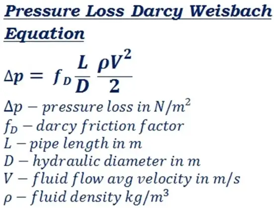
3.1.2 Pressure drop Calculation formula used in Hydraulic Calculation:
(1) Frictional pressure drop shall be calculated using the Darcy-Weisbach equation as follows:
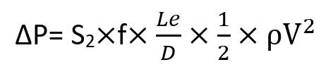
Here,
- ΔP= Frictional Pressure drop
- f= Moody’s friction factor
- Le= Equivalent length
- S2= Unit conversion factor.
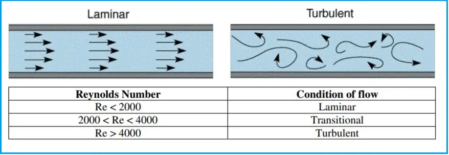
(2) For laminar flow (Reynolds number below 2000) the friction factor can be calculated as f=64/Re, Here f=friction factor.
(3) For turbulent flow (Reynolds number above 4000 the friction factor can be calculated using an equation developed by Colebrook correlation as given below:
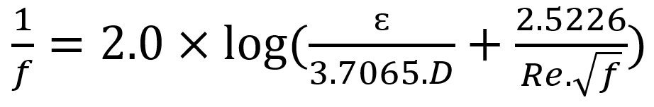
Where, ɛ=pipe inside roughness, unless otherwise specified the roughness of commercial steel pipe can be taken as 0.0457 mm.
The following are typical fluids in this category.
- – General hydrocarbon
- – Chemically treated water such as cooling water, boiler feed water, etc.
(4) Hazen and William’s empirical formula shall be applied in a hydraulic calculation, taking Hazen and Williams as
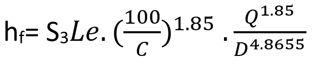
Where
- hf= Frictional head loss, m
- Le = Equivalent length, m
- C = Friction factor
- Q = Flow rate, m3/Sec
- D = Pipe inside diameter, m
- S3 = Unit conversion factor, 0.002125
The formula can be used for any liquid having a viscosity in the range of 1.13 centistokes which is the case for water at 15 °C. Friction factor C = 100, for the following service;
- – Seawater, flowing in an untreated inner surface pipe
- – Oxygen-contained and chemically untreated water such as drinking water, industrial water, etc, flowing in an untreated inner surface pipe
(5) Compressible Gas flow formulae used in the hydraulic calculation
For Low-pressure drop service: For estimating pressure drop in short runs of gas piping, Darcy-Weisbach’s formula described above is applicable and accurate, assuming pressure drop through the line is not more than 10% of the total pressure (GPSA Engineering Databook, Section 10).
For High-Pressure drop service, in ordinary gas piping, the flow is closer to adiabatic than truly isothermal. The pressure drop of adiabatic flow can be calculated using the following equations:
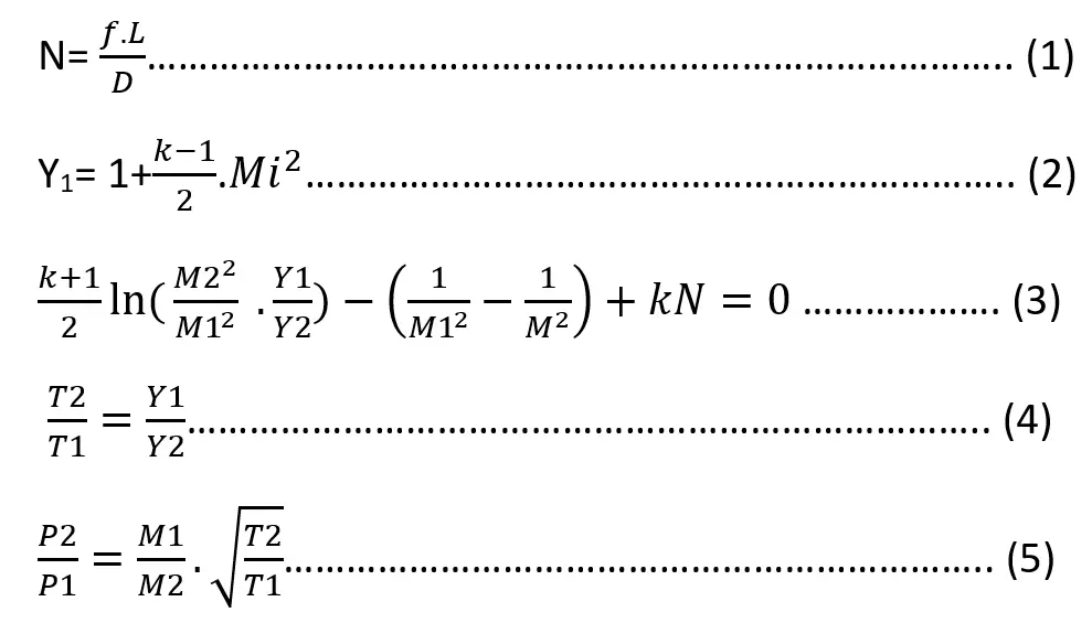
Here,
- P = Pressure (N/m2)
- T = Temperature (°K)
- N = Pipe resistance factor
- u = Velocity (m/s)
- a = Sonic velocity (m/s)
- M = Mach number = u/a
- Y = Mach number factor
- f = Moody friction factor based on average viscosity
- D = Pipe diameter (m)
- L = Pipe length (m)
- k = Cp/Cv, specific heat ratio (-)
- R = gas constant= 847.9/molecular weight ((kgf/m2) ・m3/kg-mol・°K)
- Subscript 1= Inlet & 2=Outlet.
i= 1 or 2
Calculation procedure
- Step-1: Assume downstream conditions (P2, M2, T2)
- Step-2: Calculate M1 by equation (3) as a trial and error method.
- Step-3: Calculate T1 by equation (4) with M1 from Step 2.
- Step-4: Calculate pressure drop by equation (5) with M1, T1 from Step-2, 3.
- Step-4: If P1 calculated is equal to the given inlet pressure, the calculation can be terminated. If not so, return to Step-1 with new assumed conditions.
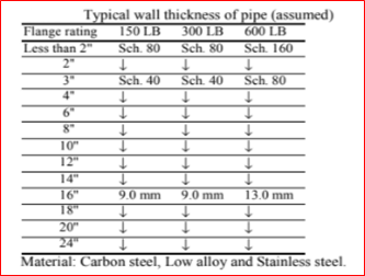
3.2 Standard Pipe Data:
3.3 Limitation of Line Size:
The lines should be sized within the limitations tabulated below (see Table 1)
| Fluid | Erosional Velocity | Sonic Velocity | Noise Velocity | Minimum Velocity | Flow pattern | Special requirement |
| Liquid-General | Yes | Yes | ||||
| Liquid-at boiling point | Yes | Yes | ||||
| Gas or vapor | Yes | Yes | ||||
| Gas/Liquid | Yes | Yes | ||||
| Steam condensate | Yes | Yes | ||||
| Slurry | Yes | Yes | Yes | |||
| Steam | Yes | Yes |
3.3.1 Erosional Velocity formula used in Hydraulic calculation:
(1) The velocity above which erosion may occur in gas/liquid two-phase flow can be determined using the following empirical equation. Ve= Ce/√ρm, where, Ve =Erosional velocity, ρm=Homogeneous density, Ce = Empirical constant normal in the range of 180-240.
(2) Water piping: The maximum velocity should be less than the values given below,
- Mortar or concrete 3.0 m/s
- Mortar lining seal coat with paint 5.0 m/s
- Steel cast iron or PVC 6.0 m/s
(3) Amine Solution:
The velocity in the Amine process should be less than the following;
- Carbon steel
- Liquid 3 m/s
- Vapor 30 m/s
- Stainless steel
- Liquid 9 m/s
- Vapor 36 m/s
3.3.2 Sonic Velocity formula used in Hydraulic calculation:
(1) The maximum velocity shall be less than 50% of the sonic velocity for continuous gas or vapor services.
(2) For intermittent services, such as pressure relief valve discharge piping, 80% of sonic velocity may be acceptable. Care should be taken over the back pressure limitations.
(3) The sonic velocity can be calculated as follows.
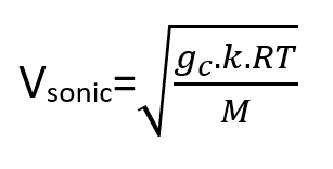
Where,
- Vsonic = Sonic velocity (m/s)
- gc = Gravity conversion factor (kgf・m/kgf・s2)
- k = Specific heat ratio = Cp/Cv
- R = Gas constant = 847.9 (kgf/m2)(m3)/(kg-mole)(°K)
- T = Temperature (°K)
- M = Molecular weight
(4) When pressure drops across the valve is relatively high, e.g. steam injection, nitrogen header, and so on, check the sonic velocity for valve downstream piping.
3.3.3 Slurry Line:
(1) Cycle oil The minimum and maximum velocities for cycle oil containing catalyst fines shall be as follows;
- Minimum velocity 1.1 m/s
- Maximum velocity 2.1 m/s
(2) Other services
If practical, flow velocity should not be less than 0.9 m/s to minimize the deposition of solids. [API RP-14E 2.3a – 1991]. The maximum velocity should be lower than the erosional velocity, which will depend on the fluids and processes. Therefore the erosional velocity will be provided by the process licenser.
3.3.4 Two-Phase Flow Pattern:
(1) The estimation method of pressure drop and flow pattern for gas/liquid two-phase flow in the hydraulic calculation is based on the following:
- Pressure drop: HTFS method
- Flow pattern: TULSA university method
(2) Flow patterns
The flow pattern is determined using the method developed by TULSA university which is based on the Taitel and Dukler method. Also, this method is applied in HTFS Handbook TM2 (Aug. 1986).
(3) The flow pattern map with the definition of coordination is as follows:
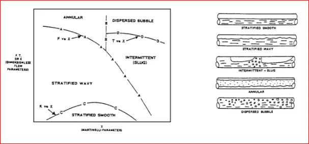
The flow pattern is defined as follows:
- Bubble flow: The gas phase is distributed as discrete bubbles in a liquid continuum. The bubbles tend to flow in the upper part of the pipe.
- Stratified flow: The separation of the liquid & gas phase is complete; the liquid is flowing at the bottom of the pipe and the gas at the top.
- Wavy flow: As the gas velocity is further increased in stratified flow, surface waves begin to build upon the liquid layer.
- Slug flow (Intermittent flow): As the gas velocity is further increased in the wavy flow region, the waves become big enough to reach the top of the pipe. These waves are propagated by gas at high velocity, often have a frothy nature, and are referred to as “slugs”.
- Annular flow: As the gas velocity increases still further, the slugs no longer occur and the flow becomes essentially annular but with a thicker film at the bottom of the pipe than at the top.
3.3.5 Guideline for Line Sizing in Hydraulic calculation:
The final line size shall be determined in the hydraulic Calculation. In order to minimize rigorous analysis, the following guidelines are useful for practical line sizing. Tables 2 to 4 show the practical pressure drops and practical velocities for each service.
| Service | ΔP100( kgf/cm2/100m) | Vpractical(m/s) | Remarks |
| Pump Suction -Boiling point liquid -Subcooled Liquid | 0.05 0.08 | ||
| Pump Discharge -Carbon steel -Stainless Steel | 0.15 1.5 | ||
| Column draw-off | 0.05 | 1.0 | |
| Liquid to reboiler | 0.05 | ||
| Liquid to CV at BP | 0.05 | ||
| Gravity flow -general service | 1.0 |
| Service | ΔP100(kgf/cm2/100m) | Vpractical(m/s) | Remarks |
| Atmospheric / Vacuum 10 kgf/cm2G and below 100 kgf/cm2G and below Over 100 kgf/cm2G | 0.01 – 0.07 0.07 – 0.20 0.20 – 0.70 0.7% of Pop | ||
| Reboiler return -Kettle type -Thermosyphon type -Furnace type | 0.02 – 0.05 0.02 – 0.05 0.18 | ||
| Compressor suction -Reciprocating -Centrifugal | 0.0-0.5 | 12 Economic velocity |
| Service | ΔP100(kgf/cm2/100m) | Vpractical(m/s) | Remarks |
| Instrument, plant air Atmospheric Up to 3.5 kgf/cm2G Up to 7.0 kgf/cm2G Up to 10 kgf/cm2G | 0.05 0.07 0.11 0.13 | ||
| Saturate steam -Below 7 kgf/cm2G -Above 7 kgf/cm2G | 0.20 0.45 | 40 – 60 30 – 50 | |
| Superheat steam -10 kgf/cm2G and below -100 kgf/cm2G and below | 0.07 – 0.20 0.20 – 0.70 | Max. 75 | |
| Steam condensate: Upstream of steam trap or control valve | 0.05 | ||
| Steam condensate: Downstream of steam trap or control valve | 0.2-0.7 | 25 | |
| Cooling Water | 0.3 | 1-4 | |
| Sea Water | 1-4 |
3.4 Equivalent Length of piping
3.4.1 Estimation of Equivalent Length for Hydraulic Calculation:
(1) Equivalent length of piping: Equivalent length should be taken from the piping layout if it is not available, the length should be taken from the plot plan, and the equivalent length (Le) of the piping will be estimated based on the straight length (Ls) as follows:
- Process area: 3.0 times Straight length (can be changed as per project specification)
- Lines on the pipe rack: 1.5 times of straight length for temperature greater than 100ᵒC & 1.2 times of straight length for temperature lower than 100ᵒC (can be changed as per project specification).
It is advisable to count the number of elbows, tees, and valves and evaluate the equivalent length, assuming piping layout for large-size or high-pressure piping.
(2) Pump suction line: When the piping layout is not available, the equivalent length of the pump suction line should be assumed as 50 m minimum for process pumps and utility pumps.
(3) Expansion loop: Thermal expansion loops are normally set for lengthy and high-temperature service lines such as an HP steam line and flare line. Since expansion loops increase equivalent length considerably, confirm the Piping Section for the expected numbers of pressure balance is tight under selected pipe size.
3.5 Pressure Drop Data
3.5.1 Pressure Drop of Instruments for Hydraulic Calculation:
(1) If the estimated pressure drop is available for the instrument, use it in the hydraulic calculation. If not, use the allowable pressure drop.
(2) If pressure drop data for an instrument is not available, data (for low viscosity service) may be assumed as follows:
- Flow orifice 0.2 kgf/cm2
- Venturi tube 0.02 kgf/cm2
- Rotameter 0.2 kgf/cm2
- Positive displacement meter 0.6 kgf/cm2 (strainer included)
- Turbine meter 0.5 kgf/cm2 (strainer included)
(3) For high viscosity service (μ > 1cP) or non-Newtonian fluid, the pressure drop shall be calculated or evaluated from the available sources such as vendor information.
3.5.2 Pressure Drop of Piping Components for Hydraulic Calculation:
The pressure drop of a permanent strainer should be taken as follows.
- 0.5 m for dirty service
- 0.3 m for clean service
3.5.3 Pressure Drop of Equipment for Hydraulic Calculation:
If estimated pressure drop data for the equipment are not available, the pressure drop for low viscosity service may be assumed as follows:
- Heat exchangers 0.3 – 0.7 kg/cm2
- Air coolers
- 0.3 – 0.5 kg/cm2 for clean service
- 1.0 – 1.5 kg/cm2 for fouled service
- Filters 0.7 kg/cm2
3.5.4 Pressure Drop of Control Valve Hydraulic Calculation:
Normally the following criteria for the control valve are used during hydraulic calculation.
(1)A control valve DP shall be determined as greater values of the following,
- -Minimum 0.7 kg/cm2 on pump loop
- -8 % of pump discharge
- – [(1.1135 x (maximum flow/normal flow))2-1] x ΔPfriction, where the ratio of maximum flow rate to normal flow rate is overdesign factor
- – 33% of ΔPfriction
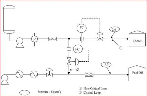
3.6 Hydraulic Circuit & Calculation Sheet
The below figure shows a hydraulic circuit,
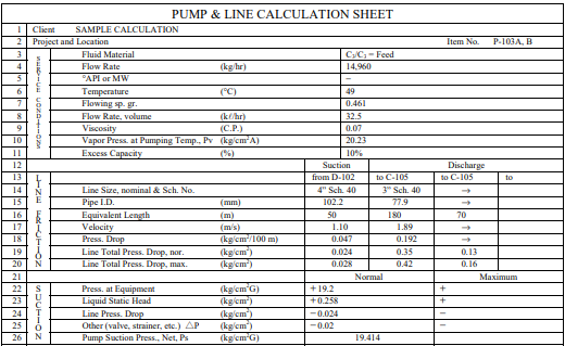
(2)The following data sheets should be prepared as a result of the hydraulic calculation.
- – Hydraulic flow diagram
- – Pressure balance
- – Flow pattern for two-phase flow
(2) The data sheet shall include the following information.
-Line sizes, Source equipment (its pressure and elevation), Pump suction and discharge pressure, equipment in the pump discharge line, their inlet pressures and pressure drops, inlet and outlet pressure of control valve, Destination, its pressure, and elevation.
(3) The following parameters should be evaluated based on the hydraulic calculation results.
– Design pressure, operating pressure, line classes, nozzle size of equipment, equipment elevation, etc.
The below figure represents an example of a hydraulic balance sheet,
4. Hydraulic Calculation Software Programs:
In the earlier days, hydraulic calculation has been performed in excel-based calculation sheets. But nowadays, various software has been developed for error-free hydraulic calculations. These software programs also save man-hours and perform the calculation faster. Common Hydraulic calculation software programs that are used widely among the EPC industries are:
- HRS System,
- Hcalc,
- Mensura Genius,
- AFT Fathom,
- Hytos,
- Hydratec,
- Fluidflow
- PASS/Hydrosystem,
- Pipenet,
- Flomaster,
- Flownex, etc
Online Video Courses on Process Hydraulics and Hydraulic Calculations
The following online video courses are extremely useful to learn and get an in-depth knowledge of Process Hydraulics and Hydraulic Calculation: