Process Flow Diagram or PFD and P&ID or Piping/Process & Instrumentation Diagram are chemical/process engineering drawings and are very important for Process, Piping, Mechanical, and Instrument Engineers and Designers of any Process Plant or Power Plants. These drawings are very useful as they convey the right amount of process information as needed during various stages of bidding, engineering design, procurement, construction, operating & commissioning phases of the process.
What is a Process Flow Diagram or PFD?
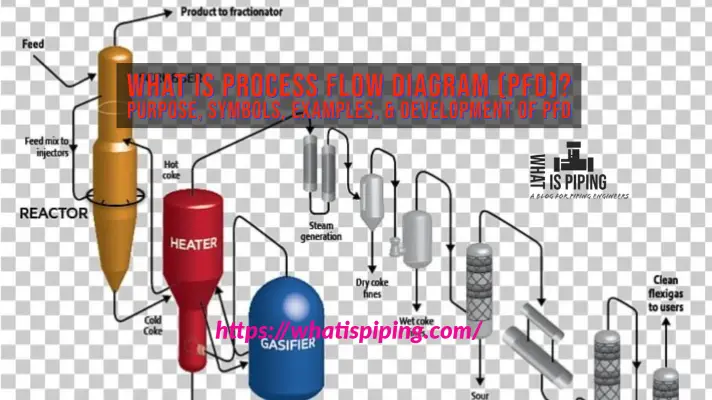
A Process Flow Diagram (PFD) shows the relationships between the major components in the system. Generally, a PFD (Fig. 1) shows only the major equipment and doesn’t show details. A PFD does not show minor components, piping systems, piping ratings, and designations. This diagram shows the flow of chemical fluids and the equipment involved in the process with the properties of flowing chemical fluids (like temperature, pressure, fluid density, flow rate, etc).
Process engineers are responsible for designing PFD based on the chemical process and thermodynamic properties of the fluid in question. Typically, process flow diagrams of a single unit process will include process piping, major equipment items, control valves, and other major valves, connections with other systems, major bypass and recirculation streams, operational data (temperature, pressure, mass flow rate, density, etc.)
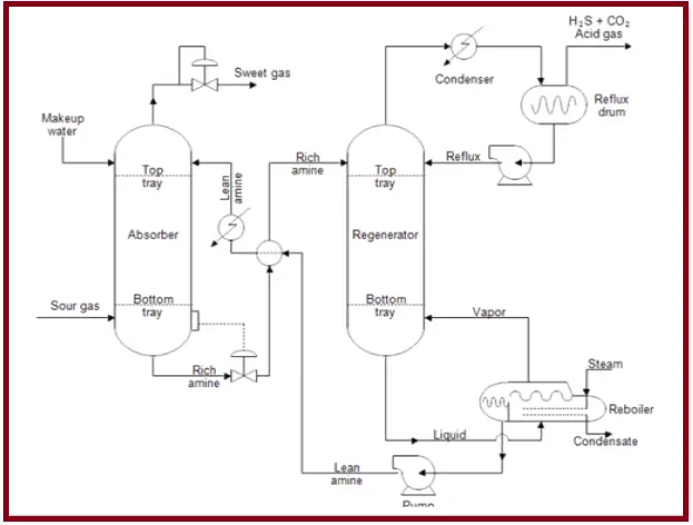
Process flow diagrams generally do not include minor components like process control instrumentation, piping systems like control loops, by-pass lines, drain lines, pipe properties like size, specification, ratings, pipe classes, pipeline numbers, components such as isolation and shut-off valves, maintenance vents and drains, relief, and safety valves, vents and drain.
What is the Piping/Process & Instrumentation Diagram (P&ID)?
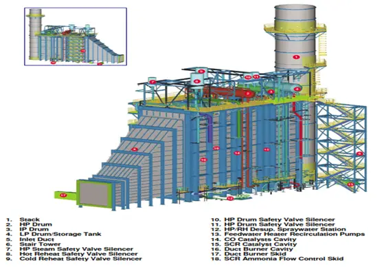
A Piping and Instrument Drawing (P&ID– Also known as PEFS, Process Engineering Flow Scheme in some engineering organizations) includes more details than a PFD. It includes both major and minor details of the chemical process. P&ID (Fig. 2) shows all major equipment, piping details like service, size, spec, rating, insulation, etc, instrumentation details like pressure, temperature, and flow instruments, control valves, pressure safety valves, meters, pipe routing information such as slope, tapping, free flow.
Instrumentation and their details are shown using standard symbols which vary from company to company.
All kinds of valves used like On-off valves, motorized valves, relief valves, and miscellaneous items like strainers, vents, drains, silencers, standpipes, etc. are shown in the P&ID.
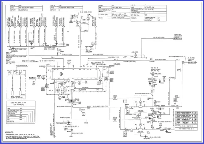
Vendor items and packages are shown with their limits and interfaces. A lot of information such as equipment design pressure, temperature, and material of construction, free-draining requirements is provided as notes in the P&ID.
Line numbers, Tag numbers, and Equipment Numbers shown in the P&ID are usually retained in the further documents and drawings created.
P&ID includes:
- Mechanical equipment with names and numbers
- Pipeline number, size, material, insulation
- Every instrument and its pneumatic/ electric signal
- Detailed control loops
- Utility lines, drain and vent lines, sampling lines, etc.
- Parallel and spare equipment and connected piping
- Isolation and shut-off valves.
- Miscellaneous – vents, drains, special fittings, sampling lines, reducers.
A P&ID does not include:
- Equipment rating or capacity
- Instrument root valves
- Manual switches and indicating lights
- Primary instrument tubing and valves
- Elbows and similar standard fittings
- Extensive explanatory notes
In both, PFD and P&ID arrows indicate the flow of materials. Normally P&IDs are a more detailed scheme of simple PFDs.
About The Author: This article is written by Mr. Khaja Najmuddin, a Piping Stress Engineer with extensive experience in the Oil and Gas sector. For more details about the author click here to refer to his LinkedIn profile.

Hi
Greetings from South Africa
Thanks for your unstoppable information you sharing on this platform.
I was always dreaming to be become an independent engineer,,but unfortunately I couldn’t full filled my dream as the market out there is in such demand for engineers.
I’m an artisan and couldn’t manage to Perseu further studies… financially,, studies were costly.
However,,, reading your outline information gives me more insight of an engineer
Kind regards
Absolutely helpful for aspiring engineers like me sir! I appreciate the efforts that have gone into creating content for this blog. Grateful.
This has really helped, thanks
This is wonderful. I’m currently working on my undergraduate plant design project which is the production of glycerol from Moringa seed oil ( an edible oil). I need help and assistance in doing the P&ID. I’ll be grateful if anyone here can help. Thank you very much.
Email: eslajags@yahoo.com