Socket welding is a permanent pipe joining methodology for welding pipe fittings and components. A range of piping applications uses socket-welded pipe fittings because of high leakage integrity and structural strength. In this write-up, we will learn about Socket weld and socket welded fittings.
What is a Socket Weld?
A socket weld involves the welding of pipe with several pipe fittings like elbows, reducers, and tees. Two pipe pieces/components are involved in socket welding. One is having a larger diameter than the other. The smaller diameter pipe is inserted in the other piece and welding is performed on the periphery of the larger piece. As no end preparation is required in socket welding, the process is easy and quick. In general, socket welding is used for small-diameter pipes, usually up to 4 inches.
Working of Socket Welding
As already defined above, socket welding is the name given for welding fittings with pipes inside them. These pipe fittings include recessed sockets where the pipes are inserted before welding. A small gap is maintained between the end of the pipe and the bottom of the socket to allow the pipe to grow/expand by the welding heat. When the gap (usually 1/16 inch) is ensured and the pipe is placed in position, fillet welding is performed at the location where the pipe diameter meets the socket.
Socket welds create effective, leak-proof, high-pressure piping and pipeline configurations for fluid transport.
Types of Socket weld pipe fittings
A range of socket weld pipe fittings and components are used in the piping industry. While welding, the pipe is inserted into the recessed part of the valve, flange, or fitting. Socket weld pipe fittings are usually referred to as SW pipe fittings and they are available in various types as listed below:
- SW Full Couplings: Used for joining two pipes together. Have threads at both ends for connecting both pipes.
- Socket Weld Half Couplings: Have threads on one end only, and the other end is generally welded.
- SW Reducing coupling: Used for connecting pipes of different diameters.
- SW equal tees: For making a branch connection of the same size.
- Socket welded reducing tees: For making a branch connection of reduced size.
- SW elbows: 90-degree and 45-degree designs for changing flow direction.
- SW unions
- Sockolet: Used to weld a smaller diameter pipe with a larger diameter pipe
- Socket Weld Cross
- SW flanges,
- Socket weld caps: socket weld pipe cap is connected to the end of a pipe to seal it.
While ordering these types of pipe fittings, you need to mention pipe diameter and pressure rating, class.
Features of Socket Weld Fittings
As socket weld pipe fittings have high-pressure ratings, they are used in a wide range of industrial applications. They are installed in pipelines to transport flammable, toxic, or hazardous chemicals safely with a low possibility of leakage. Socket weld fittings are of high quality as most of them are manufactured following ASME and ASTM specifications and standards.
Socket welding pipe fittings can also be classified based on the type of materials.
Advantages of Socket weld pipe fittings
For pipe joining, socket weld fittings provide a number of advantages like:
- Easy alignment for joining. No tack weld requirement for aligning.
- Lower risk of leakage.
- No weld metal infiltration in the pipe bore
- Cheaper to install as compared to butt welded fittings.
- No special machining requirements.
Drawbacks of Socket weld pipe fittings
Some of the disadvantages of socket weld pipe fittings are:
- Substances can accumulate in the expansion gap and those are difficult to clean.
- Internal crevices and expansion gaps associated with socket weld fittings often lead to corrosion.
- Not suitable for food industries.
Socket weld vs Butt weld fittings
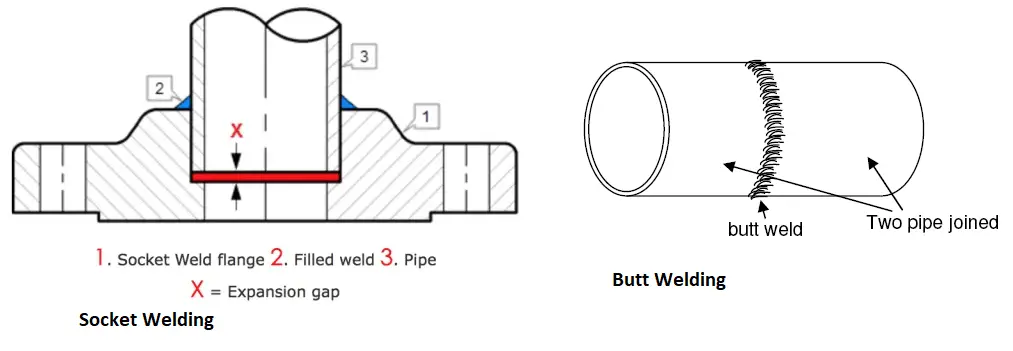
There are some major differences between socket weld fitting and butt weld fitting. The following table lists the major differences between the two types of fittings.
| Socket Weld Fitting | Butt Weld Fitting |
| ASME B16.11 provides details of socket welded pipe fittings. | Whereas, the governing standard for Butt welded pipe fittings is ASME B16.9 |
| Socket welded fittings have low strength as compared to butt-welded pipe fittings. | More strong as compared to socket weld fittings. |
| Socket-welded pipe fittings are easy to weld and bevel ends are not required. | Butt welding fittings need proper end preparation for joining. |
| SW pipe fittings are normally used for lower pipe sizes. | Butt-welded pipe fittings are more suitable for higher pipe sizes. |
| Socket-welded pipe fittings are usually avoided for high-temperature and pressure applications. | Butt weld fittings are widely used for high-temperature and pressure applications. |
Video Courses in Welding
To learn more about welding the following video courses you can refer to: