Piping Specialty items are basically a range of non-fitting items and components required to serve various functions in the piping and plumbing system. The scope of this article is to take you through a brief introduction to the Piping specialty items and their review.
When an item cannot be managed as a bulk item due to certain Process Licensor requirements, it must be procured as a special item (as these special parameters need to be informed to the vendor which cannot be done through bulk purchasing.) The first step towards this direction is marking it with a special tag on PID for easier identification on site. These special items are depicted with a symbol on the PID. Hence the process of assigning the Special item tag is important and there should be no duplication. These special items usually have a longer lead time as compared to bulk items and being special, they are also expensive.
It is also important to have the correct data as per the P&ID so that the sizes, ratings, or materials are not wrongly purchased.
Once the special tags are assigned and the list is prepared, the purchase specification is then prepared for each special item, including the scope, the material, design, end connection, packing, preservation, and painting requirements as such. The process datasheets involving the different process inputs for the individual special item are further attached to this purchase specification.
The Material requisition (which consists of the purchase specification, the process datasheets, the painting, preservation, inspection, and test plan) is then floated in the market for vendor offers. After receiving the vendor offers, the technical bid evaluation is done (which involves to and fro technical queries, which are resolved between the contractor and the vendor). Once the technical bid evaluation is finalized, it is then forwarded to the Procurement department after which the purchase order is finally placed. Then we receive the general arrangement drawings for each special item which needs to be reviewed and further approved across subsequent revisions. After which they are ready for production and further dispatched to the site once ready.
Some of the special items involved are steam traps, strainers, angle piston valves, flame arrestors, special check valves, flexible hoses and quick couplings, and sight glass.
We will just go through a quick and brief introduction for every special item mentioned above.
Steam Traps
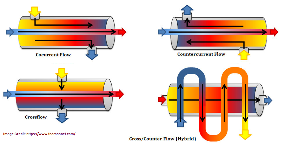
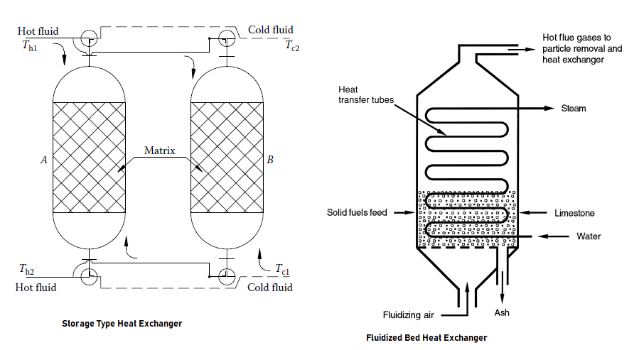
During the heat transfer process for example in a heat exchanger, both air and condensate can form and get trapped in the system, making it less effective. Hence steam traps are basically used to separate out these condensate and non-condensate gases (like air) from a pressurized steam system. Therefore, steam traps are used to trap steam and discharge the condensate. The heating efficiency in the system would be affected if the condensate is not removed, and quickly.
There are different parameters such as pressure drop, sizing, condensate load, density, flow rate, viscosity, design pressure, temperature, etc. to be considered in a trap datasheet.
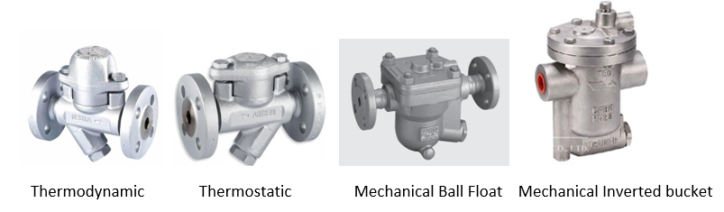
There are many types of steam traps used depending on the application such as
- Thermodynamic steam trap (works on the principle of pressure differential).
- Thermotactic steam trap (works on the principle of temperature differential).
- Mechanical traps such as ball float type and inverted bucket type.
The vendor or the process engineering department shall select the right type of trap depending on the application, the differential pressure, and the condensate and sizing load.
Most of these steam traps are equipped with integral strainers for filtering purposes.
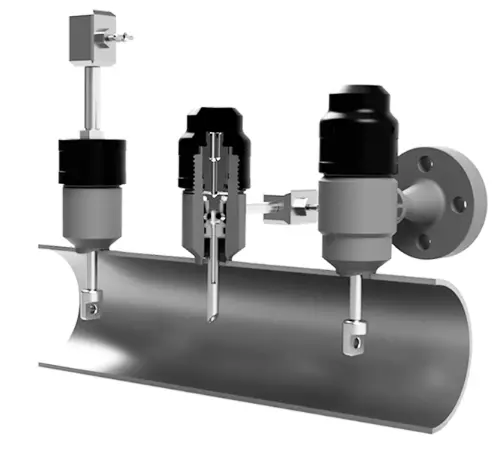
Generally, from the above, thermodynamic traps are widely used. They are also used as utility traps commonly referred to as bulk traps. They are cheaper as compared to other traps. To know more about steam traps click here. Below are the pictures of the steam traps.
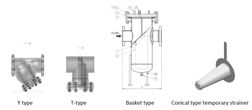
Strainers
The strainers are used in process plants to protect equipment such as valves, and steam traps from dirt, etc. The mesh size, pressure drop, opening area ratio, design temperature, and pressure are different parameters to be considered in the datasheet for strainers.
The different types of strainers are Y-type strainers, T-type strainers, Basket type strainers, and Conical type Temporary strainers. Below are the pictures of the strainers as mentioned above. More details of strainers can be found here.
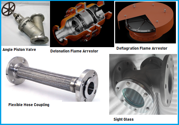
Angle Piston Valves
These are one of the most critical piping specialty items, they are mostly used at the bottom of equipment such as reactors. They have a long lead time and are also expensive.
The alpha angle of the drain connection with respect to the flow, the special service and finishing requirements, design temperature and pressure, and layout considerations, if any shall be taken into account whilst preparing the datasheet for angle piston valves.
Flame Arrestors
While transporting flammable liquids or gases, there is a possibility of flame or explosion to occur should an ignition take place.
The explosion group, the type of service, the zone classification, design pressure, temperature, and layout considerations shall be considered whilst preparing the datasheet. The vendor shall select the type of flame arrestor depending on the above parameters. There are two types of flame arrestors:
Detonation:
Inline detonation flame arrestors are specifically designed for pipelines that have a significant distance between the ignition source and the flame arrestor. In other words, they can be installed at any distance from the ignition source. They offer ultimate protection from a worst-case scenario i.e of an explosion. They have a series of mesh as shown in the figure below and based on all the above reasons they are expensive when compared to the deflagration type.
Deflagration:
End-of-line deflagration is designed to protect against atmospheric deflagration where the ignition source originates outside the system.
Inline deflagration is designed to prevent the possibility of propagation of flames in the piping systems by locating the flame arrestor in close proximity to the potential source of ignition.
Special Check Valves
Special check valves are similar to normal check valves except that they would have some special process requirements individually such as pressure drop, density, design temperature, and pressure, etc. which cannot be managed through bulk and would require a different special item tag. These special process parameters shall be taken into consideration whilst preparing the datasheet.
Flexible Hoses and Quick couplings
Flexible hoses along with quick couplings are used for process and utility services (Plant air, Cooling water, Nitrogen, and Steam). The end connections, the design pressure, and temperature, the length of the hose required are certain parameters that require to be included in the datasheet.
Different ends connection for the hose such as Camlock type, wing nut type, and Swagelok type are used depending upon the services.
Sight Glass
Sight glasses as piping specialty items are pieces of equipment with industrial glass used to observe the levels of liquids in a plant. They allow the plant personnel to monitor the pressure changes. The different process parameters here are given by process. The design conditions such as pressure and temperature, fluid service, and the type of glass required are certain parameters to be included in the datasheet.
List of Piping Specialty Items
Some of the most common piping specialty items are already introduced in the above section. Some other piping specialty items are listed below:
- Static Mixer
- Special Equal Tee
- Grit trap
- Sand Trap
- Liquid Trap
- Air release vacuum breaker
- Bug Screen
- Chemical Injection
- Insulation Joints, Insulation Flanges, Insulation Kits
- Bursting Discs
- Sample cooler
- Valve interlock
- Quick release Coupling
- Oblique Connection
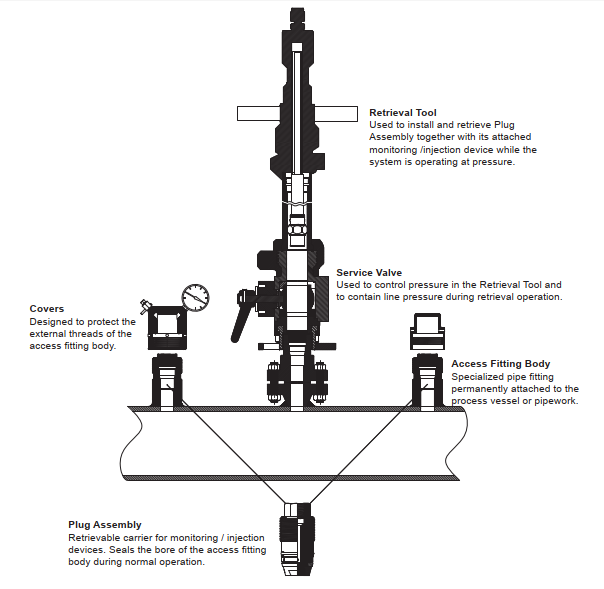
- Corrosion Coupon
- Pipe Expansion Joint
- Corrosion probe
- Fabricated and Special forged items and nozzles according to customer drawings
- Test Plugs
- Ball Joints
- Flexible Connectors
- Fire Hydrant