A demister pad is a device that can remove micron-size entrained liquid droplets from a gas/vapor stream. Demister means the removal of the mist, and hence the main function of demister pads is to remove liquid particles and dust particles from the gaseous phase. Sometimes they are also known as mist eliminators or vapor pads. Demister pads are often found to be installed just below the top vapor outlet of a vapor-liquid separator or distillation tower. In this article, we will learn about the working, types, features, and applications of demister pads.
For gas and liquid separating and filtering, Demister pads serve as an efficient and economical product. In chemical, pharmacy, petroleum, papermaking, food, mineral, and other industries, Demister pads are widely used in gas and liquid separator towers. Some of the applications of demister pad include
- Inlet Scrubbers
- Compressor System
- Three Phase Separators
- Cold Separators
- Glycol Dehydration
- Compression Operations in Natural Gas Processing
- Amine Absorption Column
- Steam Drums
- Seawater Desalination Plant
- Flue Gas Desulphurisation
- Catalytic Cracking
- Gas Absorption and Stripping
- Condensation
- Gas Compression
- Dehumidification and Drying
- Spray Removal and Desalination
- Crude Oil Distillation
- Alkylation
- Stripping Operation in Desulphurization and Hydro Fining Process
- Sulfur Condensers
- Knockout Drums
The demister with its high filtering efficiency (usually greater than 99%) is composed of knitted wire mesh. They are specially woven and interlocked to ensure even and smooth meshes for efficient filtering. Depending on the different filtering requirements, the mesh design can be customized.
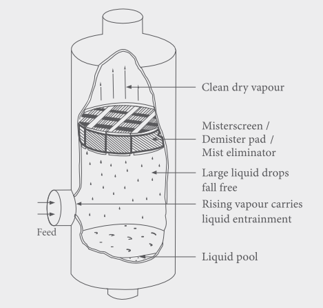
Working of a Demister Pad
The demister pads function by coalescing smaller liquid droplets to grow bigger by creating an obstruction in the flow path and then isolating them by gravity. When a demister pad is installed in the path of a rising gas stream, the wire meshes create an obstruction. This causes the mist particles to collide with the mesh filament where the mist diffuses on the filament surface to create droplets that follow along the filaments of the two-wire intersection. These droplets stick together and grow bigger and when they are too heavy to rise with the gas stream, they isolate. The gas stream is not affected by the obstruction and can easily escape.
Separation of the liquid from the gas improves the operating condition by optimizing the process indicators. It also reduces the corrosion possibility of the equipment which in turn extends equipment life. The liquid droplet separation also increases the recovery of valuable materials, thus protecting the environment and decreasing air pollution.
The main objective of demister pads to generate obstruction can be achieved by a variety of geometries. Demister pads can be a mesh-type coalescer, vane pack, or other structure.
The efficiency of demister pads is dependent on the following parameters:
- Droplet Size
- Mesh Wire Size
- Surface Area of Mesh
- Pad thickness, and
- Physical Properties of the System
The main design parameters for demister pads are
- Liquid Loading
- Gas and Liquid Viscosity
- Gas Pressure
- Surface Tension
Types of Demister Pads
Demister pads are usually available in the following four types:
- Standard type,
- Efficient type,
- High penetration type, and
- Shock absorber type.
Materials for Demister Pads
Industrial demister pads are manufactured from metallic or plastic materials. The common metallic materials are:
- Stainless steel (For water solution, nitric acid, fatty acid, reduced crude fraction)
- Carbon steel.
- Copper.
- Titanium alloy.
- Nickel Alloys (Food products, Caustic Soda)
- Monel (Diluted acid, Alkalis)
On the other hand, the common plastics (for corrosive service at moderate temperatures) used to manufacture knitted mesh demister pads are:
- PP.
- PE.
- PVC.
- FEP.
- PTFE.
- PVDF
Characteristic Features of Demister Pad
A good demister pad should possess the following characteristic features:
- High porosity and less pressure drops.
- Simple structure.
- Lightweight and easy to transport.
- Large surface area and high separating efficiency.
- Corrosion and rust resistance.
- Durable and long service life.
- Easy to install, operate and maintain.
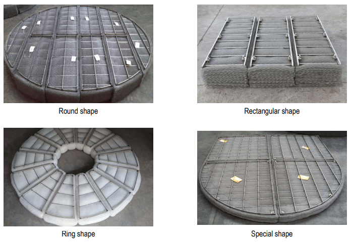
Demister pads are available in the following shapes (Refer to Fig. 2):
- Round shape
- Ring shape
- Rectangular shape
- Customized shape
Construction of Demister Pads
Demister pads are designed into various structures to achieve high tensile strength, better efficiency, and higher bearing capacity. The pad surface can be smooth or ginning. For small-diameter applications, the demister pads are made from integral structures whereas they are made from separated structures for large-diameter applications. Support grids are sometimes provided in form of round bars or flat bars to provide greater strength.
Demister Pad Installation
They can be installed vertically or horizontally depending on the application. There are two types of installation; upload type and download type.
Upload-type demister pad installation is suitable for places where the manhole is located above the demister pad. On the contrary, download types pad installation is suitable where the manhole is located below the demister pad.
Demister Pad Specifications
Industrial demister pads are usually specified using the following parameters:
- Sheet Size
- Mesh per inch/Mesh Size
- Wire Size
- Type and finish
- Materials
- Outside Diameter
- Grid requirements
- Application/Fluid Service
- Horizontal or vertical installation
- Operating Process Parameters
- Efficiency required
Advantages of Demister Pads
Demister pads or mist eliminators provide various benefits:
- High separation efficiency
- Low-pressure drop
- Easy installation and low maintenance
- High resistance to fouling
- Economical