As a piping engineer, you must have heard the name of Navisworks, a very useful software tool. The plant review software, Navisworks is widely used by plant design professionals from the Construction and Design industries of Oil and Gas, Chemical and Petrochemical, Power, Metal, Mining, and various other industries. In this article, we will discuss the components, functions, versions, and benefits of Navisworks software.
What is Navisworks?
AutoDesk Navisworks is a project review 3D software package that allows Architecture, Engineering, and Construction professionals to review integrated models and data during the design and preconstruction stage for the betterment of the project outcomes. The software was originally developed by Sheffield, a UK-based developer which was acquired by AutoDesk in 7une 2007.
Functions of Navisworks
Navisworks is a very useful software tool in piping design engineering. It allows users to open, view, and combine 3D design models. Novisworks gives the real 3D model feel of the plant at the design stage. Autodesk Navisworks users can easily navigate around the plant in real time and perform several activities like commenting, redlining, measuring, creating viewpoints, etc. Some of the important functions that can be achieved by using the Navisworks software:
- Coordination
- Clash Detection/ Interface Detection
- 5D Project Scheduling
- Rendering
- Quantification
- PDF like publishing
- Construction Simulation
Versions of Navisworks Software
There are three versions of the Navisworks software. They are:
- Navisworks Freedom,
- Navisworks Simulate and
- Navisworks Manage.
Navisworks Freedom is a free viewer for viewing the native NWD files. Navisworks Simulate is the base-level software that includes various useful functionalities except for Clash Detective. Navisworks Manage is the top-level software that includes all the features.
Components of Navisworks
Navisworks software package is built around a core module known as Roamer that has a number of in-built functionalities as listed below:
- Roamer for opening models from a range of 3D design and laser scan formats and combining them into a single 3D model. The core part of Navisworks, Roamer helps users in navigation around the model in real-time and reviews the model.
- Publisher allows Noavisworks users to publish the complete 3D model into a single NWD file for opening using the free viewer Navisworks Freedom.
- Clash Detective functionality enables interference detection to find clashes and geometry conflicts or faults in the design.
- The renderer or Presenter allows the users of Navisworks software to apply materials and lighting to the model to generate photorealistic images and animations.
- Quantification allows users to automatically make material estimates, measure areas, and count building/plant components.
- The Timeliner adds a 4D simulation feature. The Navisworks user can easily link geometry to times and dates for simulating the construction or demolition of the model over time. Additionally, various project scheduling software packages like Microsoft Project or Primavera products can be linked to import task data.
- The animator feature of the Navisworks software allows the users to animate the model and interact with it.
- Scripter allows users to set up a collection of actions to happen by meeting certain event conditions.
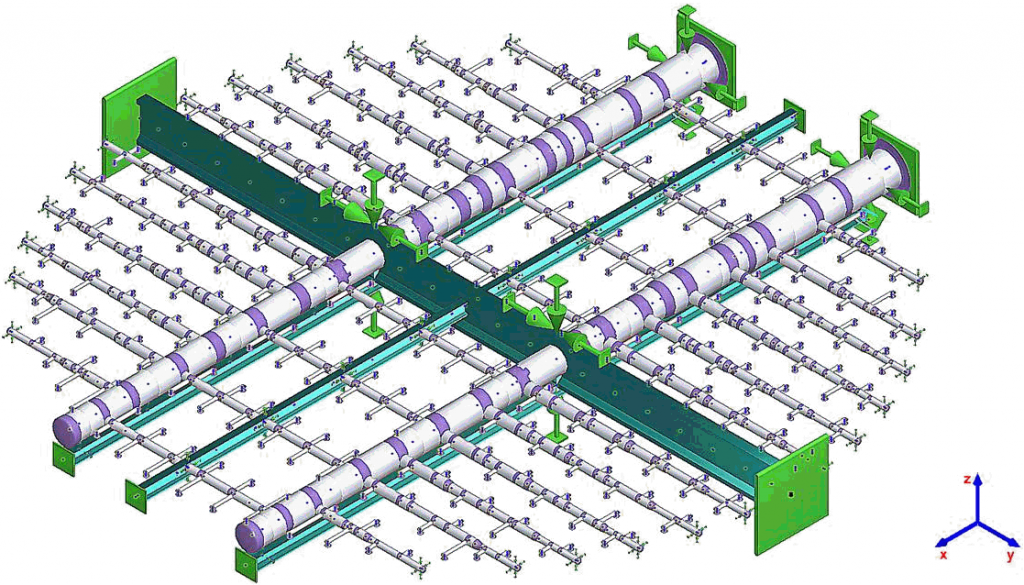
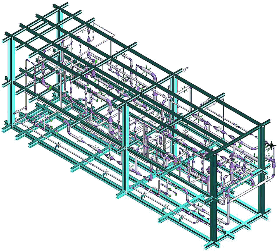
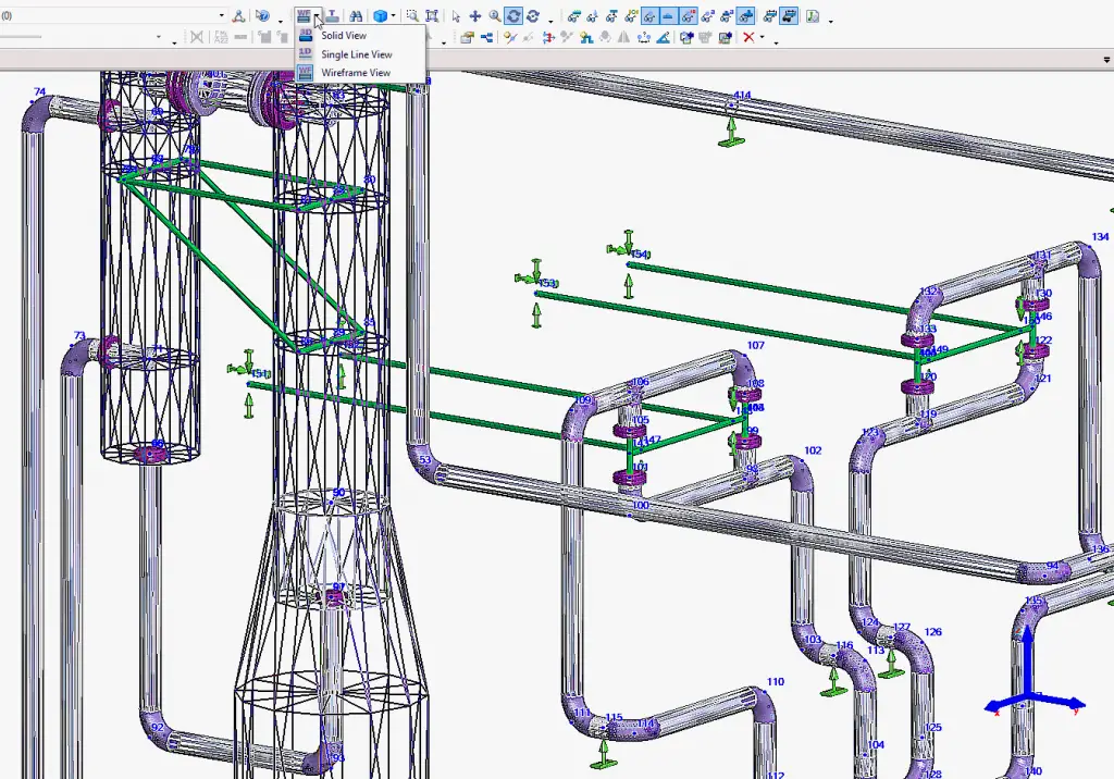
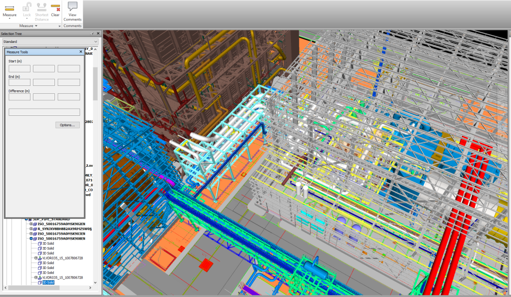
Refer to Fig. 1 below that shows a typical plant in Navisworks Freedom.
File Formats supported by Navisworks
Similar to other Autodesk software, the Navisworks (Simulate and Manage) software package, too, supports a wide range of file formats. Some of the Navisworks-supported file formats are listed below:
Navisworks Software File formats:
- NWC – The Cache file (.) nwc is basically the snapshot of the current model. NWC files are created automatically when a native file is loaded.
- NWD –This is the file format for publishing the model to coordinate and view later in different other software packages.
- NWF –This is a file format where users usually work and append the files. This contains the links to all appended files.
There are various other design file formats that Navisworks support. Some of them are:
- AutoCAD Drawing – .dwg, .dxf (up to AutoCAD 2018)
- MicroStation (SE, J, V8, & XM) – .dgn, .prp, prw (up to v7, & v8)
- 3D Studio Max – .3ds, .prj (up to 3ds Max 2018)
- ACIS SAT – .sat, .sab (all ASM SAT, up to ASM SAT v7)
- DWF – .dwf, .dwfx (all versions)
- CATIA – .model, session, .exp, dlv3, .CATPart, .CATProduct, .cgr (up to v4, & v5)
- IFC – .ifc (IFC2X_PLATFORM, IFC2X_FINAL, IFC2X2_FINAL, IFC2X3, IFC4)
- IGES – .igs, .iges (all versions)
- Informatix/MicroGDS – .man, .cv7 (v10)
- Inventor – .ipt, .iam, .ipj (up to Inventor 2018)
- CIS/2 – .stp (STRUCTURAL_FRAME_SCHEMA)
- JT Open – .jt (up to v10)
- NX – .prt (up to v9)
- Revit – .rvt (up to 2011–2022)
- RVM – .rvm (up to v12.0 SP5)
- SketchUp – .skp (v5 up to 2015)
- PDS Design Review – .dri (legacy file format, support up to 2007)
- STL – .stl (binary only)
- VRML – .wrl, .wrz (VRML1, VRML2)
- Parasolid – .x_b (up to schema 26)
- FBX – .fbx (FBX SDK 2017)
- Pro/ENGINEER – .prt, .asm, .g, .neu (Wildfire v5, Creo Parametric v1-v3)
- STEP – .stp, .step (AP214, AP203E3, AP242)
- Solidworks – .prt, .sldprt, .asm, .sldasm (2001, plus 2015)
- PDF – .pdf (all versions)
- Rhino – .3dm (up to v5)
- Solid Edge – .stp, .prt
Advantages of using Navisworks
Navisworks software package helps users in various activities to reduce the project time and cost. The main advantages of Navisworks are:
- Generation of a single federated model to visualize and unify design and construction data.
- Identify and resolve clash and interference problems much before actual construction begins which results in time and cost savings for the onsite rework.
- Helps in easy collaboration with other discipline teams by connecting with Navisworks.
- Controlling the project schedules and costs by using 4D and 5D simulation.
- Easily capturing the material quantities from 2D or 3D designs.
- Aggregated models take lesser time to load than other similar software packages.
- Several export options for various tools are available.
- Using the software is quite easy. Even beginners can easily learn the software without much challenge.
Download AutoDesk Navisworks Freedom
As already mentioned, Navisworks Freedom is a viewer software. The viewing tool is provided by AutoDesk for free. It helps the user to view the whole project in 3D. Navisworks freedom supports NWD and 3D DWF files. The Navisworks freedom software package comes with the following features:
- The free Navisworks freedom includes all the required sets of navigation tools, including Walk, Zoom Box, Pan, Orbit, Look Around, Zoom, Examine, Fly, and Turntable
- The software supports the real-time display of materials and lighting.
- It enables the viewing of model hierarchy, object properties, and embedded review data. The Navisworks Freedom also includes creating viewpoints, animations, redlines, and comments.
As the software is free, It can be easily downloaded from the following links to install on your PC.