A piping manifold is a system of pipes, valves, and fittings that are used to distribute or control the flow of fluid, such as water, gas, or oil, in a pipe system. It is a central point where multiple pipes come together and are distributed to different locations. A piping manifold can be used for various purposes such as distributing fluid from a main pipe to several smaller pipes, controlling the flow of fluid to different parts of a building or industrial facility, or isolating a section of a pipe system for maintenance or repair.
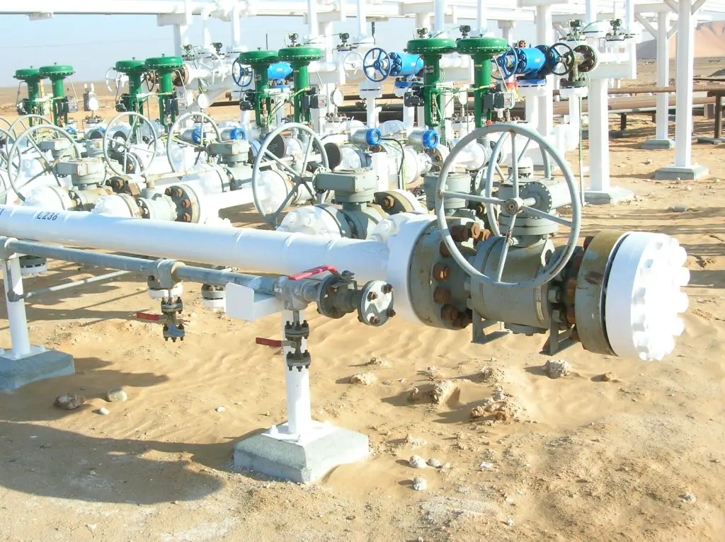
A manifold can be made of various materials such as metal, plastic, or even glass and it can be designed for different pressure and temperature conditions, depending on the application. The manifold typically consists of inlet and outlet ports, which are connected to the main pipe and the smaller pipes respectively, and control valves that regulate the flow of fluid through the system. Some manifolds also have pressure gauges, temperature gauges, and other monitoring devices to measure the flow and condition of the fluid. Fig. 1 below shows a typical water injection piping manifold.
Applications of Piping Manifold
Piping manifolds are widely used in the oil and gas, HVAC, plumbing, and industrial process piping systems, and can be found in a variety of applications such as, in buildings, ships, oil rigs, pipeline systems, and many other industrial facilities.
Purpose of Piping Manifold
A piping manifold is a component in a piping system that serves as a central hub for distributing fluids or gases to multiple branches or locations. The purpose of a piping manifold is to control and distribute the flow of fluids (liquids or gases) in a piping system and to provide a convenient location for connecting and disconnecting pipes, valves, and other components. Manifolds can also be used to control pressure and temperature, and to facilitate maintenance and repair of the piping system.
Piping Manifold Design
Designing a piping manifold involves several steps:
- Identify the fluid or gas that will be flowing through the manifold and its properties, including viscosity, density, and flow rate.
- Determine the number and location of branches or outlets that the manifold will need to distribute the fluid or gas to.
- Select the appropriate materials for the manifold and its components, taking into consideration factors such as corrosion resistance, pressure and temperature ratings, and compatibility with the fluid or gas.
- Determine the appropriate pipe size, flow rate, and pressure drop for the manifold based on the fluid or gas properties and the number of branches or outlets.
- Choose the type of valves and controls that will be used in the manifold, such as ball valves, gate valves, or globe valves.
- Create a detailed layout and drawing of the manifold, including the location of pipes, valves, and other components.
- Consider the safety and maintenance aspects, ensuring that the manifold is designed to be easily accessible for maintenance and repair and that it meets all relevant safety codes and regulations.
- Finally, consult with the appropriate professionals and conduct pipe stress analysis, thermal analysis, and hydraulic analysis as needed.
It’s also important to keep in mind that some standard codes and regulations may apply to the design and fabrication of the manifold, and it’s essential to comply with them.
Types of Piping Manifolds
There are several common types of piping manifolds, each with its own unique features and applications. Some of the most common types include:
Branch Manifold: A branch manifold is a simple type of manifold that splits a single flow of fluid or gas into multiple branches or outlets. It typically has one inlet and multiple outlets and is commonly used in applications such as HVAC systems, water distribution systems, and gas distribution systems.
Loop Manifold: A loop manifold is similar to a branched manifold, but it creates a looped flow pattern. It typically has multiple inlets and multiple outlets and is commonly used in applications such as process control systems and industrial cooling systems.
Block Manifold: A block manifold is a more complex type of manifold that combines several functions into one compact unit. It typically includes multiple inlets, outlets, valves, and other components, and is commonly used in applications such as hydraulic systems, lubrication systems, and refrigeration systems.
Valve Manifold: A valve manifold is a type of manifold that is primarily used to control the flow of fluid or gas through a piping system. It typically includes one or more valves, such as ball valves or gate valves, and is commonly used in applications such as process control systems, instrumentation systems, and industrial automation systems.
Choke Manifold: A choke manifold is a type of manifold that is used to control the flow rate and pressure of the fluid or gas. It typically includes one or more chokes, such as needle valves or orifices, and is commonly used in applications such as oil and gas production, and well testing.
Again depending on the purpose of the manifold they are popular by various names as listed below:
- Water injection Manifold (Fig. 1)
- Gas lift manifold
- Oil manifold, etc
Pipeline Manifolds
A pipeline manifold is a device used to distribute or control the flow of fluids in a pipeline system. It typically consists of a series of valves, fittings, and other components that can be configured to regulate the flow of fluid through the pipeline. Manifolds are commonly used in industrial and commercial applications, such as oil and gas production, water treatment, and HVAC systems. They can be used to control the flow of fluids at a specific point in the pipeline or to branch the flow of fluids to multiple locations.
Difference between a Header and a Manifold
A header and a manifold both refer to devices used to distribute or control the flow of fluids in a pipeline system. However, the terms are often used in slightly different ways.
A header is generally used to refer to a large pipe or tube that collects fluid from multiple sources and sends it to a central location. For example, in a heating system, multiple smaller pipes might bring hot water to a header, which then sends the hot water to different parts of the building.
A manifold, on the other hand, is often used to refer to a device that splits the fluid flow into multiple smaller streams or combines multiple fluid streams into one. Manifolds are often used to control the flow of fluids at a specific point in the pipeline or to branch the flow of fluids to multiple locations.
In summary, a header is a pipe that collects fluid from different sources and sends it to a central location, while a manifold is a device that splits or combines the flow of fluids at a specific point in the pipeline.
Factors for Selecting the Right Piping/Pipeline Manifold
There are several factors to consider when choosing the right type of piping manifold for a specific application. Some of the most important factors include:
- Flow rate: The required flow rate of the system will determine the size and type of manifold needed.
- Pressure: The operating pressure of the system will also affect the design and selection of the manifold.
- Type of fluid: The type of fluid being transported will determine the materials and coatings that should be used to construct the manifold.
- Temperature: The operating temperature of the system will affect the materials and coatings that should be used to construct the manifold.
- Space constraints: The available space for the manifold will affect the size, shape, and configuration of the manifold.
- Safety and regulations: The manifold must be designed and built to comply with relevant safety and regulatory standards.
- Maintenance and repair: The ease of maintenance and repair for the manifold should also be considered in the selection process.
- Cost: The cost of the manifold should be considered in relation to the overall budget for the project.
It is important to consult with a piping expert to determine the best type of manifold for a specific application and take into consideration all the factors above.
Difference between a Manifold and a Skid
A manifold and a skid are both used in industrial and commercial applications as a way to control or distribute the flow of fluids, but they are different types of equipment.
A manifold is a device that splits the fluid flow into multiple smaller streams or combines multiple fluid streams into one. Manifolds are often used to control the flow of fluids at a specific point in the pipeline or to branch the flow of fluids to multiple locations. They can be made of different materials such as steel, aluminum, or plastics and they can be customized to specific applications.
A skid, on the other hand, refers to a pre-assembled unit that contains one or more pieces of equipment, such as pumps, valves, and/or control systems, mounted on a metal frame or platform. Skids are often used in industrial and commercial applications, such as oil and gas production, water treatment, and HVAC systems. They are designed to be easily transported and installed and can be used to process and control the flow of fluids within a specific area or process.
In summary, a manifold is a device that splits or combines the flow of fluids at a specific point in the pipeline, while a skid is a pre-assembled unit that contains one or more pieces of equipment such as pumps, valves, and/or control systems mounted on a metal frame or platform, used to process and control the flow of fluids within a specific area or process.