Temporary pipe support refers to a temporary structure or device used to support pipes during construction, maintenance, or repair work. It is essential to provide adequate support for pipes to prevent damage, deformation, or misalignment during installation or operation. The term temporary necessarily signifies that these supports will be removed after the commissioning of the piping or pipeline system.
Temporary pipe supports can take various forms, depending on the type of pipe and the work being performed. Some examples include pipe clamps, pipe hangers, pipe stands, pipe rollers, and pipe saddles. These devices are typically designed to be adjustable and easy to install and remove, allowing them to be quickly and efficiently deployed in a wide range of situations.
Temporary pipe supports are typically used in situations where permanent supports are not yet in place or where the existing supports are not sufficient to hold the weight of the pipes. They may also be used to provide additional support during periods of high stress or when the pipes are being subjected to external forces, such as wind or vibration. Before moving the Piping and Pipelines systems into their final position, they might be placed on temporary supports for proper working.
Requirements for Temporary Pipe Supports
Temporary pipe supports are essential during the construction, maintenance, or repair of pipelines for several reasons:
Prevent damage: Pipes are often heavy and can easily deform or be damaged if not properly supported during construction, maintenance, or repair work. Temporary pipe supports help prevent this damage by providing a stable and secure platform for the pipes.
Ensure correct alignment: Temporary pipe supports can help ensure that pipes are correctly aligned during installation, preventing misalignment that could lead to leaks or other issues.
Allow for adjustments: Temporary pipe supports are typically adjustable, making it easy to fine-tune their position and angle as needed. This adjustability is essential for ensuring that pipes are properly supported and aligned during construction, maintenance, or repair work.
Facilitate work: Temporary pipe supports can also make it easier for workers to perform their tasks safely and efficiently. By providing a stable and secure platform for the pipes, workers can focus on their work without having to worry about the pipes shifting or moving.
Overall, temporary pipe supports are crucial for ensuring the safe and efficient installation, maintenance, and repair of piping and pipeline systems, and help to prevent costly and time-consuming issues such as leaks, deformation, or misalignment.
Selecting a Temporary Pipe Support
When selecting temporary pipe supports, several factors should be taken into account, including:
Pipe size and weight: The temporary pipe support must be capable of supporting the weight of the pipe being worked on, as well as any fluids or gases that may be flowing through the pipe. Additionally, the support must be compatible with the diameter and thickness of the pipe.
Work environment: The type of work being performed, the location of the work, and the conditions of the work environment must be considered when selecting temporary pipe supports. For example, if work is being performed in a hazardous environment, the support must be made from materials that are resistant to corrosion, heat, or chemicals.
Adjustability: The temporary pipe support should be adjustable to accommodate changes in pipe diameter or to ensure proper alignment. Support that is too rigid may lead to deformation or misalignment of the pipe.
Portability: The temporary pipe support should be easy to transport and install, particularly if the work site is located in a remote or hard-to-reach area.
Safety: The temporary pipe support should be designed to minimize the risk of accidents or injuries during installation, use, and removal.
Compatibility: The temporary pipe support should be compatible with the type of pipe being worked on, whether it is a metal, plastic, or composite pipe.
Hence, selecting the right temporary pipe support requires careful consideration of the specific requirements of the work being performed, as well as the properties of the pipe and the work environment. By selecting the right temporary pipe support, the risk of damage to the pipe and the work site can be minimized, and work can be completed safely and efficiently.
Typical Examples of Temporary Pipe Supports during Design Stage
There are some instances when temporary pipe supports are suggested during the design phase. Some of the typical examples are:
Temporary Support during Hydrotest
Sometimes when large-diameter gas/vapor pipes are hydro-tested, temporary supports are added to transfer the loads. As the pipes carry vapor or gas, The actual permanent supports are generally not designed based on the water-filled weight. So, during a hydro test, the imposed loads on permanent civil members can be more than the design value. For this reason, temporary supports are added to carry part of the loads during the hydrostatic test and keep loads of permanent supports within their design load values.
Temporary Support During Rotary Equipment Alignment
Aligning the piping flange and rotary equipment flange is an important activity. Due to the strain-sensitive nature of the rotating equipment like pumps, turbines, compressors, etc, the loads imposed during alignment must be reduced. Sometimes, pipe routing is such that providing permanent support exceeds the nozzle allowable loads but to qualify the alignment checking criteria support is required. In such instances, temporary support is suggested by the pipe stress engineer which takes care of the flange alignment issues. But note that those temporary supports must be removed once the flange alignment is finished and the pump is ready for commissioning.
Pipe stress engineers usually mark such requirements in the piping stress isometrics and the information is passed to the construction team by a note in the isometric.
Typical Forms of Temporary Pipe Supports
Some of the most widely used forms of Temporary Pipe Supports are:
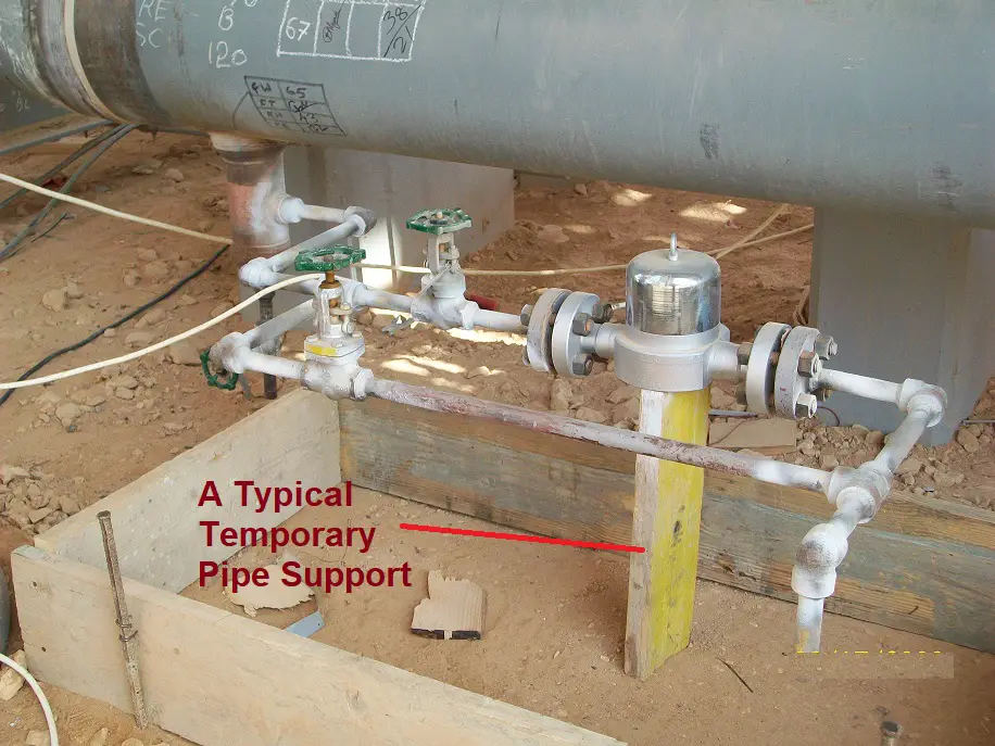
Wooden Blocks: Wooden blocks are simple yet effective temporary pipe support that can be easily made and customized to fit the specific needs of the maintenance project. They can be cut to size and stacked to provide the necessary support.
Adjustable Pipe Stands: Adjustable pipe stands are metal frames that can be adjusted to different heights and angles. They can support pipes of various sizes and shapes, making them a versatile choice for temporary pipe support during maintenance.
Pipe Clamps: Pipe clamps are a type of adjustable support that can be attached to the pipe to hold it in place. They can be used to provide support at specific points along the length of the pipe.
Pipe Rollers: Pipe rollers are cylindrical supports that are placed under the pipe to allow it to roll as it expands and contracts. They are commonly used in areas where there is significant movement or vibration.
Jacks: Jacks are hydraulic or mechanical devices that can be used to lift and support pipes during maintenance. They can be adjusted to different heights and angles and can support heavy loads.
It’s important to note that the specific type of temporary pipe support used will depend on factors such as the size and weight of the pipe, the duration of the maintenance project, and the specific requirements of the maintenance task.
Online Video Courses on Piping Support
To learn more about piping support design and engineering you can opt for the following video course.