Pipe caps are a type of pipe fitting to cover the pipe end. In the Piping, Plumbing, and Pipeline industry, pipe end caps are widely used to block the ends of pipes. They work in a similar fashion to pipe plugs or blind flanges. Even though this is a very important pipe fitting, most of the time the significance of pipe caps is overlooked. In this article, we will explain some details about pipe cap fittings; their types, materials, standards, specifications, and differences with plugs and blind flanges.
What is a Pipe Cap?
A pipe end cap is a pipe fitting that held the pipe content within itself by blocking the end parts. It acts as a protective device for the plumbing, piping, and pipeline system by not allowing outside matters to enter the inside of the pipe. Due to this pipe caps are also known as pipe end protectors. Industrial pipe caps are widely used in domestic, commercial, and industrial water supply lines, Steam pipes in power plants, and various oil, gas, and chemical lines in process and chemical industries.
Pipe Cap Materials
A range of materials is used to manufacture piping end caps. Depending on the pipe material and service, pipe cap materials are selected. Some of the common industrial pipe cap materials are:
Pipe caps are manufactured in various shapes to cater to various application demands. Some of the common pipe cap shapes are:
Round
Square
Rectangular
“I” Shape Cap
Oval
Hemispherical
“U” Shape Cap
Hex Cap etc.
Pipe Cap Standards
ASME B16.9 provides pipe dimensions, ratings, testing, tolerances, and marking requirements for Steel Piping cap fittings. Usual pipe end caps are manufactured from NPS 1/2 inches through 48 inches with pipe schedules 10, 20, 30, STD, 40, 60, 80, XS, XXS, 100, 120, 140, and 160 as applicable. Other pipe end caps standards are:
ASME B16.11
DIN 2617
DIN 28011
MSS SP 43
EN 10253
Types of Pipe Caps
Pipe caps are classified based on their applications, material of construction, construction features, etc.
Depending on the construction features, the following pipe cap types are found:
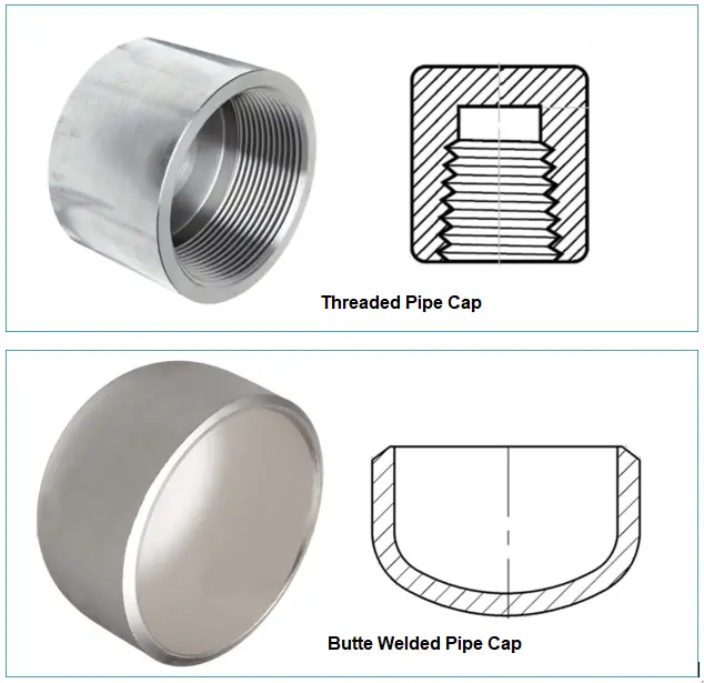
Threaded Caps: Threaded pipe caps have female threads to fit the pipe end with the caps. The thread can be straight or tapered.
Welded Caps: Welded pipe caps can be either butt welded or socket welded caps.
Tapered Caps: These types of pipe caps have tapered sides that help in a close fit. Tapered caps can be used as a multi-functional pipe fitting and can be used with male and female NPT threads, male straight threads, and straight tubes and bars.
Anti-roll Caps: These pipe cap types are round in shape but with a square end to prevent pipes and tubes from rolling.
Fig. 1: Threaded and Welded Pipe Caps
Depending on pipe cap materials, they can be classified as:
Metallic Pipe Caps: Made from metals like Steel, Aluminum, etc. and
Non-metallic Pipe Caps: Made from non-metals like plastics.
Specification of Pipe Caps
Pipe end caps are specified by various parameters as listed below:
Shape: Shape of pipe caps (Round/Square/Rectangular)
Head type of Round Pipe caps: (flange or slotted head, knurled or faceted head, retaining head, and tear tab)
Length and Width for Rectangular pipe caps.
Thread type and size: NPT/BSP/Metric
Design Standard: ASME/DIN
Coating/Polishing/Galvanizing Requirements
Pipe Caps vs Plugs
Plugs are piping also serve a similar function that a pipe cap serves. But there is a major difference between the pipe cap and the pipe plug. Pipe caps usually have female thread whereas pipe plugs have male threads. It means a pipe is inserted into the threads of a pipe cap whereas the plug is inserted into the pipe. Other differences between the two are:
Purpose: A pipe cap is used to close off the end of a pipe permanently to make it a dead end, whereas a pipe plug is generally used to temporarily seal the pipe end for maintenance or testing.
Installation: Pipe caps are can be welded or threaded while pipe plugs are generally threaded.
Pressure rating: Pipe caps are designed to handle the system pressure but pipe plugs usually do not handle system pressure.
Pipe Caps vs Blind Flanges
A blind flange is a type of piping flange that serves a similar function as a pipe cap. However, there are some distinct differences between a pipe cap and a blind flange. These are listed below:
Purpose: A pipe cap closes the end of a pipe permanently, but a blind flange is used to isolate a section of a pipeline or seal off a pressurized system.
Production: Blind flanges are forged or cast components whereas pipe caps are generally made by forming.
Installation: Pipe caps are installed by welding or screwing whereas blind flanges are generally installed by bolting and a gasket is inserted in between.
Seal: Pipe caps provide permanent sealing whereas blind flanges are used to provide a pressure-retaining barrier with a mating flange. Blind flanges are used to connect or disconnect parts of piping or valves.
Face type: Pipe caps have a flat or convex end face, while blind flanges have a raised face.
Pressure testing: Blind flanges can be used for pressure testing, while pipe caps cannot.
Maintenance: Being bolted, blind flanges can be easily removed for maintenance or repair, while pipe caps are permanent and cannot be easily removed.
Cost: Blind flanges are typically more expensive than pipe caps due to their higher level of functionality.
Online Video Course on Piping and Pipe Fittings
To enrich yourself with piping and pipe fitting details you can opt for the following online video courses
A pipe union is a type of pipe fitting that creates a secure and semi-permanent connection between two pipes. The pipes can easily be separated without causing any piping deformation. Pipe union connections are mostly used for small bore pipe connections. Whenever an easy assembly and disassembly along with a positive sealing is required, pipe union fittings are used. Common pipe unions are usually manufactured in a size range from 1/8 inches to 4 inches.
Parts of a Pipe Union Fitting
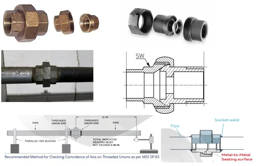
A pipe union has three parts; a male end, a female end, and a nut (Refer to Fig. below). The male and female ends of the piping union are sealed together in the nut to act as a single pipe union assembly. The female end has threads on the inside surface whereas the male end has threads on the outside surface. The nut provides the required sealing pressure to the union joint.
The threaded pipe union is threaded to be NPT per ASME B1.20.1 whereas the nut is straight thread as per ASME B1.1. The seating surfaces of the joint shall be integral metal-to-metal, ball-to-cone design.
Applications of Pipe Unions
As pipe unions have a high probability of leakage, their use is generally limited to non-hazardous and non-flammable services. The use of pipe unions is found in the following systems:
Non-critical Process piping systems with low pressure and temperatures
Plumbing Applications.
Pipe Unions
Types of Pipe Unions
There are two types of pipe unions that are found in applications as listed below:
Ground Joint Union: It comprises an angle that is cut into the piping union to make the two sections meet to increase the joint surface area which helps in proper seating. It consists of three pieces.
Flange Union: In this type of union, a pair of flanges hold two pipes together by screwing them on the ends of the pipes. This is usually used in plumbing services to hold both pipes together. It consists of only two pieces.
Again, depending on the joint connection, there are two types of pipe unions; threaded union and socket welded union.
Materials for Pipe Unions
Industrial pipe unions are made from various materials. Some of the common pipe union materials are:
Difference between Pipe Coupling and Pipe Union | Pipe Union vs Pipe Coupling
Pipe unions are quite similar to pipe couplings. However, they have some differences as mentioned below:
1. Pipe Connection:
Two coupled pipes screw together directly, one inside the other. While taking the pipes apart, every pipe that connects to the coupled pipe needs to turn.
While in a pipe union, the two pipe ends don’t screw into one another—they each screw into a third piece. When one pipe needs to come apart from the other, the union piece simply screws onto one of the two pipes completely. If both ends of a pipe are attached using a union, the pipe may be removed on its own without unscrewing the other pipes in the system.
2. Joining Method:
Pipe couplings are available in three pipe joining modes; threaded, butt welded, and socket welded. On the other hand, pipe unions only have two pipe joining modes; threaded and socket welded.
3. Use:
Pipe couplings can be used in comparatively high-pressure services as compared to pipe union connections. Couplings are used in pipe racks whereas unions are used for steam trap assemblies and control valve manifolds. Couplings are used as a piping/pipeline extension while unions are more versatile as they are used with other pipe components as well.
4. Cost:
The cost of pipe unions is comparatively higher than the cost of pipe couplings.
5. Purpose:
Pipe couplings are generally used as a permanent joint, whereas pipe unions are specifically used for parts requiring maintenance and repair for easy disengagement.
Possible Causes of leakage from pipe union
The following are some of the probable causes that can create a leakage problem from pipe unions.
Improper or low assembly torque of the collar
Imperfections of the metal-to-metal seat
Dirt on the metal-to-metal seat
High friction in the collar threads
Piping misalignment causing improper seating or uneven tightening
High vibration during operation
In addition to the possible cause of leakage through pipe thread or socket weld failure.
In certain applications, a pipe union as a pipe fitting is used as a protective system to avoid galvanic corrosion. Plastic pipe unions when used with two pipes made of different metals, act as a barrier for electronic movement from one pipe metal to the other. The physical separation slows down the galvanic corrosion process.
Online Video Course on Piping and Pipe Fittings
To enrich yourself with piping and pipe fitting details you can opt for the following online video courses
An anti-surge valve, also known as a surge-anticipating valve, is a type of control valve (surge relief valve) used in fluid systems to prevent overpressure and pressure surges that can damage equipment or cause system failure. It is typically used in systems that have rapidly changing flow rates, such as in turbocharged engines, compressors, and pumps. The valve is designed to open and release pressure when the system pressure exceeds a pre-determined set point, allowing the system to operate within a safe pressure range and preventing damage to the system.
Functions of an Anti-Surge Valve
The main function of an anti-surge valve is to protect equipment and systems from overpressure and pressure surges that can occur during rapid changes in flow rate. Some of the specific functions of an anti-surge valve include:
Preventing damage to the equipment: by releasing pressure when the system pressure exceeds a set point, the valve helps to prevent damage to the system and its components.
Maintaining system stability: by regulating pressure, the valve helps to maintain the system stability and prevent system failure.
Improving system efficiency: by preventing pressure surges, the valve can improve system efficiency by reducing the amount of energy required to operate the system.
Reducing noise: by releasing pressure, the valve can also reduce noise in the system caused by pressure surges.
Minimizing downtime: by protecting the system from overpressure and pressure surges, the valve helps to minimize downtime and reduce maintenance costs.
Controlling the flow: anti-surge valves can be used to control the flow of fluid or gas in the system.
Protecting compressors and pumps: anti-surge valves are commonly used in systems that have rapidly changing flow rates, such as in turbocharged engines, compressors, and pumps.
Working of Anti-Surge Valves
An anti-surge valve works by monitoring the system pressure and opening to release pressure when the pressure exceeds a pre-determined set point. The valve is typically installed in the system at a location where the pressure is highest and most susceptible to surges.
The valve typically consists of a valve body, a valve seat, a spring, and a piston or diaphragm. When the system pressure is within the safe range, the spring keeps the valve closed, and the piston or diaphragm is held against the valve seat, preventing flow through the valve.
When the system pressure exceeds the set point, the pressure acts against the piston or diaphragm, compressing the spring and lifting the valve of the seat. This allows the system pressure to be released through the valve, reducing the pressure to a safe level.
When the pressure drops back to the set point, the spring forces the valve back onto the seat, closing the valve and stopping the flow. Some anti-surge valves are also equipped with a control system that can automatically adjust the set point to match the changing conditions of the system, while others have manual adjustments.
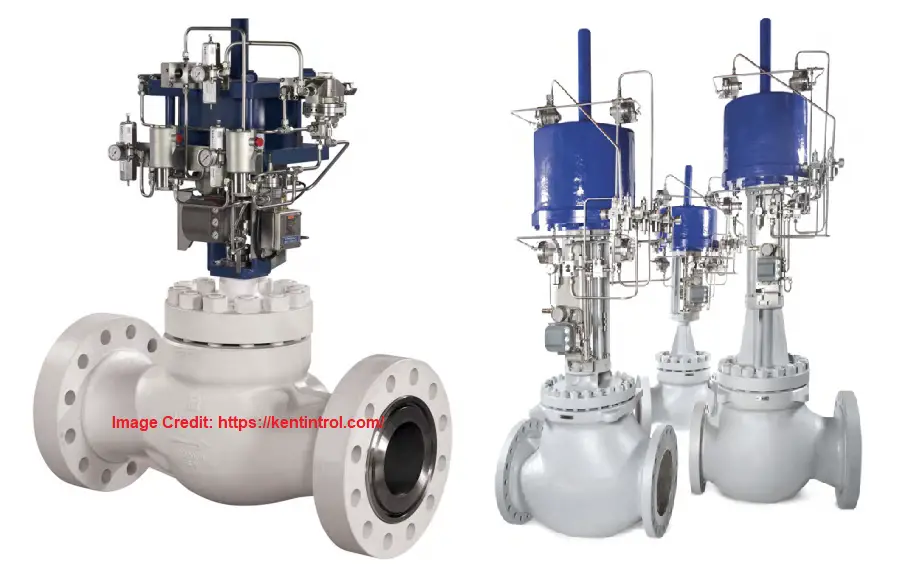
Anti-surge valves are typically designed to open and close quickly, in order to respond quickly to pressure changes and protect the system from overpressure and pressure surges. Fig. 1 below shows typical anti-surge valves.
Fig. 1: Typical Anti-Surge Valves
Anti-Surge Valve Requirements
Anti-surge valves have several requirements that need to be considered when selecting and installing them in a system:
Set point: the set point of the valve is the pressure at which the valve will open and release pressure. It is important to select a set point that will protect the system and its components from overpressure and pressure surges.
Flow rate: the valve must be able to handle the flow rate of the system in order to effectively release pressure. The valve size and type must be selected based on the flow rate of the system.
Pressure drop: the valve must be able to release pressure without creating a significant pressure drop in the system. The pressure drop must be minimized in order to maintain system efficiency. The design shall be sufficient to handle high-pressure drops if the situation arises.
Response time: the valve must respond quickly to pressure changes in order to protect the system from overpressure and pressure surges. The response time of the valve must be fast enough to meet the needs of the system.
Material: the valve material must be compatible with the fluid or gas in the system in order to prevent corrosion or damage to the valve.
Environment: the valve must be able to withstand the environmental conditions of the system, such as temperature, vibration, and external impacts.
Control: the valve must be equipped with a control system that can automatically adjust the set point to match the changing conditions of the system or manual adjustments.
Safety: the valve must be designed and installed in a way that ensures safety for the operators and maintenance personnel.
Maintenance: the valve must be designed for easy maintenance and repair, to minimize downtime and reduce maintenance costs.
Cost: the cost of the valve must be considered in relation to the overall cost of the system and the potential savings from preventing damage and downtime.
Good Stroke Speed: the anti-surge valve must be having good stroke speed
Size: the valve shall be properly sized to control the surge.
Valve Construction: To handle extreme service conditions, the construction must be robust.
Design of Anti Surge Valve
Designing an anti-surge valve involves several steps, including:
Define the system requirements: The first step in designing an anti-surge valve is to define the requirements of the system, including the set point, flow rate, pressure drop, response time, and material compatibility.
Determine the surge volume: The surge volume is the volume of fluid that needs to be released by the anti-surge valve in order to prevent overpressure and pressure surges. This can be calculated by using system models and simulations.
Select the valve size and type: Based on the surge volume, the valve size and type can be selected. The valve size should be large enough to handle the flow rate and the type should be appropriate for the fluid or gas in the system.
Consider the control system: An anti-surge valve must be equipped with a control system that can automatically adjust the set point to match the changing conditions of the system. It could be manual adjustment too.
Consider the environment: The valve must be able to withstand the environmental conditions of the system, such as temperature, vibration and external impacts.
Testing: Once the valve has been designed and built, it should be tested to ensure that it meets the requirements of the system and is able to effectively release pressure and prevent overpressure and pressure surges.
It’s important to note that anti-surge valves are a critical component in systems that have rapidly changing flow rates, and the design should be carried out by experienced engineers and based on established standards and guidelines.
Anti-Surge Valve Specification
To specify an anti surge valve the following parameters must be defined in the datasheet:
There are many manufacturers of anti-surge valves worldwide, some of the well-known ones include:
Dresser Masoneilan
Fisher Control Valves
Flowserve
KSB
Metso
Neles
Pentair
Spirax Sarco
Velan
Beker Hughes
Emerson Automation Solutions.
These manufacturers offer a wide range of anti-surge valves in different sizes, types, and materials to meet the needs of different systems and applications. They also provide technical support and service to ensure proper installation, operation, and maintenance of the valves. It’s important to note that the selection of the manufacturer and supplier should be based on their reputation, brand, certifications, standards compliance, and technical support service.
Anti Surge Valves in Compressors
Anti-surge valves in compressors are used to prevent overpressure and pressure surges that can occur in systems with rapidly changing flow rates. Click here to learn about Centrifugal compressor Surge and Control. The valve is typically installed in the compressor system at a location where the pressure is highest and most susceptible to surges.
When the compressor is working, the flow of gas is steady and the pressure remains within a safe range. However, when the compressor is shut off or when the flow rate suddenly decreases, the pressure in the system can rise rapidly. This is called a “surge” and if not controlled, it can cause damage to the compressor and the system.
An anti-surge valve in a compressor system functions by monitoring the system pressure and opening to release pressure when the pressure exceeds a pre-determined set point. This allows the pressure to be released, reducing it to a safe level and preventing damage to the compressor and the system.
Anti-surge valves in compressors are designed to open and close quickly, in order to respond quickly to pressure changes and protect the system from overpressure and pressure surges. They are also equipped with a control system that can automatically adjust the set point to match the changing conditions of the system, ensuring the safe and efficient operation of the compressor.
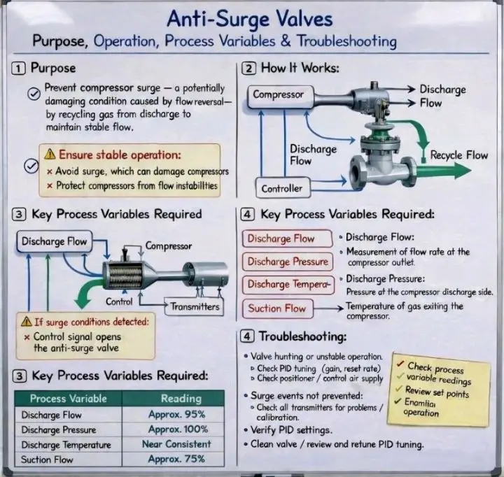
The following image, in a nutshell, explains some details about Anti-Surge Valves:
What is a Vortex Breaker? Applications, Types, Design, and Working of a Vortex Breaker
A vortex breaker is a device that is used to prevent the formation of vortices, or swirling patterns of fluid flow, in equipment or piping system. Vortexes can occur when fluid flows through a bend or restriction in the vessel or pipe and can cause problems such as increased turbulence, reduced flow efficiency, and increased wear and tear on the pipes and other components.
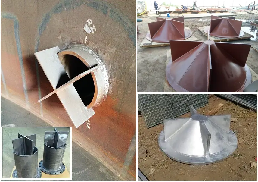
A vortex breaker is typically a small, cylindrical, triangular-shaped, or cross-shaped device that is installed in the vessel/pipe at the location where the vortex is likely to form. The device creates a disturbance in the fluid flow that breaks up the vortex before it can form, thus preventing the problems caused by vortexes. Vortex breakers are commonly used in applications such as industrial cooling systems, process control systems, and oil and gas production.
They can be installed either inside or outside the vessel/pipe, in vertical or horizontal positions, and their design depends on the fluid properties, flow rate, and pipe size.
Effect of Vortices on Flow
The main reasons behind avoiding a vortex formation are
They create an obstruction in the smooth flow.
Vortex flow draws down gases inside it and creates a two-phase flow which has several drawbacks.
Vortices disrupt the flow pattern inside the pipe or nozzle and can create erosion of pipes and fittings.
The occurrence of a vortex in a fluid system leads to a reduction of pressure. So, the requirement of pumping force increases.
Applications of a Vortex Breaker
Vortex breakers are commonly used in a variety of industrial and commercial applications where fluid flow through a piping system is involved. Some of the most common applications of vortex breakers include:
Industrial cooling systems: Vortex breakers are often used in industrial cooling systems to prevent the formation of vortices in the cooling water, which can reduce the efficiency of the system and cause damage to the pipes and other components.
Process control systems: Vortex breakers are used in process control systems to prevent the formation of vortices in fluids such as chemicals, oil, and gas, which can interfere with the accuracy of flow measurement and control.
Oil and gas production: Vortex breakers are used in oil and gas production to prevent the formation of vortices in the production fluids, which can cause problems such as decreased production rates, increased wear and tear on the equipment, and increased safety risks.
Water treatment systems: Vortex breakers are used in water treatment systems, such as in the intake of water from rivers or lakes, where they prevent the formation of vortices that can lead to the entrainment of debris or aquatic life.
Fire-protection systems: In fire-protection systems, vortex breakers are used to prevent the formation of vortices in the water supply, which can interfere with the flow of water to the fire hose, reducing the effectiveness of the system.
HVAC systems: Vortex breakers are used in HVAC systems to prevent the formation of vortices in the airflow, which can reduce the efficiency of the system and cause damage to the ducts and other components.
The use of vortex breakers can improve the efficiency and performance of the system, reduce maintenance costs, and improve safety and reliability.
Design of a Vortex Breaker
Designing a vortex breaker involves several steps:
Identify the fluid that will be flowing through the pipe and its properties, including viscosity, density, and flow rate.
Determine the location where the vortex is likely to form, and the pipe size and configuration at that point.
Select the appropriate materials for the vortex breaker, taking into consideration factors such as corrosion resistance, pressure and temperature ratings, and compatibility with the fluid.
Determine the appropriate size and shape of the vortex breaker based on the fluid properties, pipe size, and flow rate.
Choose the type of vortex breaker that will be used, such as a cylindrical or triangular shape.
Create a detailed layout and drawing of the vortex breaker, including the location, size, and shape.
Consider the safety and maintenance aspects, ensuring that the vortex breaker is designed to be easily accessible for maintenance and repair.
Conduct a simulation of the flow, including computational fluid dynamics (CFD) analysis, to verify the design and identify any potential issues.
Consult with the appropriate professionals, such as engineers or fluid dynamics experts, and comply with any relevant industry standards or codes.
Keep in mind that the design of a vortex breaker depends on the specific application, the fluid properties, and the pipe size and configuration, so it’s essential to consider these factors when designing a vortex breaker.
Working of a Vortex Breaker
A vortex breaker works by disrupting the flow of fluid and preventing the formation of vortices, or swirling patterns of fluid flow, in a piping system.
Vortexes can occur in a piping system when fluid flows through a bend or restriction in the pipe, such as an elbow or valve. As the fluid flows through the bend, it creates a swirling pattern, or vortex, that can cause problems such as increased turbulence, reduced flow efficiency, and increased wear and tear on the pipes and other components.
When the fluid flows into the vortex breaker, it is forced to flow around it and the vortex breaker creates a separation in the flow, breaking the vortex and preventing it from forming. The vortex breaker also helps to increase the flow efficiency, reducing the pressure drop, and improving the performance of the system.
It’s important to note that the design and the position of the vortex breaker are critical in order to achieve the desired results. The fluid properties, the flow rate, and the pipe size must be taken into account when designing the vortex breaker.
Fig. 1: Typical Vortex Breakers
Types of Vortex Breakers
There are several major types of vortex breakers, each with its own unique features and applications. Some of the most common types include:
Cylindrical vortex breaker: A cylindrical vortex breaker is a small cylindrical device that is installed in the pipe to prevent the formation of vortices. It is typically made of metal or plastic, and it’s placed in a perpendicular position to the fluid flow. It’s commonly used in industrial cooling systems and process control systems.
Triangular vortex breaker: A triangular vortex breaker is similar to a cylindrical vortex breaker, but it has a triangular shape. It’s also placed in a perpendicular position to the fluid flow. It’s commonly used in oil and gas production, and water treatment systems.
Plate vortex breaker (Disc or Cross type): A plate vortex breaker is a flat plate that is installed in the pipe to prevent the formation of vortices. It’s typically installed in a vertical or horizontal position, and it’s commonly used in HVAC systems, fire-protection systems, and process control systems.
Spike vortex breaker: A spike vortex breaker is a small device that has a spike-like shape. It’s typically installed in a vertical position, and it’s commonly used in industrial cooling systems and process control systems.
Spiral vortex breaker: A spiral vortex breaker is a small device that has a spiral shape. It’s typically installed in a vertical position and it’s commonly used in oil and gas production and process control systems.
It’s worth noting that the choice of vortex breaker depends on the specific application, the fluid properties, and the pipe size and configuration. Additionally, the design and the position of the vortex breaker are critical in order to achieve the desired results, so it’s essential to consult with experts and comply with industry standards or codes.
Vortex Breaker Manufacturers
There are several reputed manufacturers of vortex breakers, including:
Spirax Sarco: Spirax Sarco is a well-known manufacturer of vortex breakers and other flow control products. They offer a wide range of vortex breakers for various industries and applications.
Fluid Components International (FCI): FCI is a leading manufacturer of vortex breakers and other flow measurement and control products. They offer a wide range of vortex breakers for various industries and applications.
Vortab: Vortab is a manufacturer of vortex breakers and other flow control products. They offer a wide range of vortex breakers for various industries and applications.
Vortex Flow Control: Vortex Flow Control is a manufacturer of vortex breakers and other flow control products. They offer a wide range of vortex breakers for various industries and applications.
Pro Flow Dynamics: Pro Flow Dynamics is a manufacturer of vortex breakers and other flow control products. They offer a wide range of vortex breakers for various industries and applications.
Badger Meter: Badger Meter is a manufacturer of vortex breakers and other flow measurement and control products. They offer a wide range of vortex breakers for various industries and applications.
Flow-Tech Industries: Flow-Tech Industries is a manufacturer of vortex breakers and other flow control products. They offer a wide range of vortex breakers for various industries and applications.
This list is not exhaustive and there are many other manufacturers of vortex breakers. It’s important to research different manufacturers and products before making a purchase to ensure that the vortex breaker is suitable for the specific application and that the manufacturer has a good reputation for quality and reliability.
Vortex Breaker in Tanks
A vortex breaker in tanks refers to a device or structure that is designed to prevent the formation of vortices or swirling patterns of fluid flow within a tank. These vortices can occur when fluid is being pumped into or out of a tank, or when the fluid level in the tank is changing.
The vortices can cause problems such as increased turbulence, reduced flow efficiency, and increased wear and tear on the tank and its components. The vortex breaker is typically installed at the inlet or outlet of the tank, or at the surface of the fluid within the tank.
Vortex breakers in tanks can be of different types and designs depending on the application and the fluid properties. Some common types of vortex breakers in tanks include:
Roof-mounted vortex breaker: A roof-mounted vortex breaker is a device that is installed on the roof of a tank to prevent the formation of vortices at the surface of the fluid. It’s commonly used in oil and gas storage tanks.
Surface-mounted vortex breaker: A surface-mounted vortex breaker is a device that is installed at the surface of the fluid in a tank to prevent the formation of vortices. It’s commonly used in industrial cooling systems, and process control systems.
Inlet-mounted vortex breaker: An inlet-mounted vortex breaker is a device that is installed at the inlet of a tank to prevent the formation of vortices when fluid is being pumped into the tank. It’s commonly used in water treatment systems and fire-protection systems.
Outlet-mounted vortex breaker: An outlet-mounted vortex breaker is a device that is installed at the outlet of a tank to prevent the formation of vortices when fluid is being pumped out of the tank. It’s commonly used in industrial cooling systems, and process control systems.
Vortex breakers in tanks are designed to improve the efficiency and performance of the system, reduce maintenance costs, and improve safety and reliability. It’s important to consider the fluid properties, flow rate, and tank size and configuration when designing the vortex breaker for the tank.
Vortex Breaker in Pump Suction
A vortex breaker in pump suction refers to a device or structure that is designed to prevent the formation of vortices, or swirling patterns of fluid flow, in the suction line of a pump. Vortexes can occur in the suction line of a pump when the fluid is being drawn into the pump and can cause problems such as reduced flow efficiency, cavitation, and increased wear and tear on the pump and its components.
A vortex breaker in pump suction is typically a small, cylindrical, or triangular-shaped device that is installed in the suction line near the pump. The device creates a disturbance in the fluid flow that breaks up the vortex before it can form, thus preventing the problems caused by vortexes. The disturbance is created by the shape and the position of the vortex breaker in the pipe.
The use of a vortex breaker in pump suction can improve the efficiency and performance of the system, reduce maintenance costs, and improve safety and reliability. It’s important to consider the fluid properties, flow rate, and suction pipe size and configuration when designing the vortex breaker for the pump suction.
What Are As-Built Drawings? Construction Drawings vs As-Built Drawings
As-built drawings are engineering drawings that depict the actual physical characteristics of a plant, building, or structure as it exists once the construction is complete. During actual plant construction, there may be many deviations from the original design drawings. Those changes or modifications are marked on the original drawing with red colors to prepare as-built drawings. Because of these red hand marks over the original design drawing sheet, as-built drawings are also known as red-line drawings. In this article, we will learn the importance of piping as-built drawings.
What is an As-built Drawing?
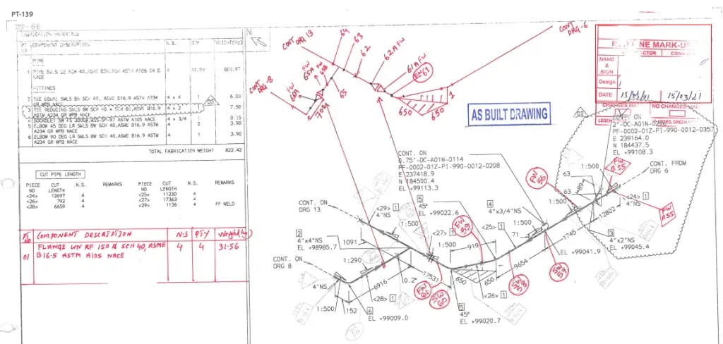
Preparing as-built drawings is one of the main processes of every construction project. An as-built drawing is an engineering document that depicts each and every modification, field change, shop drawing change, pipe routing change, extra work, etc. In a single sentence, an as-built drawing can be defined as an engineering drawing that informs any design change/deviation from the original design document. As-built drawings are also known as record drawings. Fig. 1 below shows a sample as-built drawing of a piping isometric.
Fig. 1: Sample As Built Piping Isometric Drawing
As-built Drawing Requirements
As-built drawings provide several benefits, including:
Documenting the actual plant construction: As-built drawings provide information on the actual plant that is constructed at the site. Precise details about the changes performed at any interim construction stage are known from the as-built drawings. The record of the actual physical characteristics of the pipes, buildings, or structures are required for maintenance, repairs, and future renovations, and the as-built drawings serve those purposes.
Updation of design 3-D models for future use: The information shared through the as-built drawings is used to update the 3D design models to match the actual site configuration. These help in easy tracking for future works. As-built drawings can provide information that can be used for future expansion or remodeling of the project.
Facilitating asset management: By providing a comprehensive record of the physical characteristics of an actual plant, structure, or building, As-built drawings help with proper asset management.
Saving time and money: As-built drawings can help in identifying potential issues before they become major problems, which in turn saves time and money in the long run.
Future Buying: As-built drawings are an important document that provides future buyers with a clear idea of what he is getting for their price. It also forms a strong foundation to conduct any future modifications.
Who is Responsible for As-built Drawings?
The responsibility for preparing red-line or as-built drawings typically falls on the architect, engineer, or contractor who is responsible for the actual plant or building construction. For an oil and gas project, the site engineers create the as-built drawings. Any design changes that site engineers had to make during construction due to any unforeseen reason are marked as part of the as-built drawing.
In some cases, a separate team or individual may be hired specifically to create as-built drawings. However, the person responsible for creating as-built drawings must have a comprehensive understanding of the plant, structure, or building to accurately document its actual physical characteristics.
Later, if anything changes during the maintenance work, those changes must be recorded by the concerned maintenance engineers. There could be various reasons for deviations from the actual design drawing and all those changes must be updated in the as-built drawing and properly stored for future reference.
Note that in some cases, the plant owner made the creation of an as-built drawing a criterion for successful project handover and commissioning. Also, certain local regulations need final as-built drawings as part of certifications, permits, inspections, and legal issues.
Contents of an As-built Drawing
As-built documentation shall comprise the data that is critical for the safe and efficient operation of the plant or facility after commissioning and handover. As-built drawings record construction changes to produce sufficient information. In general, a typical as-built drawing should include the following details:
Changes in materials, dimensions, installations, fabrications, locations, etc.
Dates that changes were made.
Related shop drawings and appendices
Changes made as a result of the final inspection.
Unanticipated obstacles confronted and solutions decided.
Any specific design change
Working outside the project scope
As you can see in Fig. 1, for the as-built piping isometric, the pipe route change with proper dimension and component description is mentioned clearly in red ink. The document is stamped as As-Built and the dates on which the changes are mentioned are clearly depicted.
Characteristic Features of As-Built Drawings
Even though the creation of as-built drawings can vary a bit from one organization to another. They usually have the following features:
As-built drawings must be prepared during or immediately after the construction of the facility.
The changes shall be marked in red ink over the original drawings. For small projects, as-built drawings are usually done by hand-marking with pens. However, bigger projects can use software, typed documents, etc.
All as-built drawings must be clearly stamped as As-built.
The changes and description must be clear.
Abbreviations are usually not used in as-built drawings.
Construction Drawings vs As-Built Drawings: Differences between As-Built Drawing and Construction Drawing
Construction drawings and as-built drawings are two different types of architectural or engineering drawings that are used in the construction process. The main differences between the two are:
Purpose: Construction drawings are used to guide the construction process, while as-built drawings are used to document the actual physical characteristics of a building or structure after it is completed.
Content: Construction drawings typically include detailed plans, elevations, sections, and other information that is necessary for the construction process, such as specifications and material lists. As-built drawings, on the other hand, include information on the actual physical characteristics of the building or structure, such as the location of walls, doors, windows, and other features, as well as the location and details of electrical, plumbing, and mechanical systems.
Timing: Construction drawings are created before construction begins, while as-built drawings are created after construction is complete.
Audience: Construction drawings are primarily used by contractors, builders, and construction workers to build the project, while as-built drawings are used by the building owner, maintenance staff, and building authorities for reference, compliance, and future use.
Accuracy: Construction drawings are based on the design plans and may include some assumptions or estimates, while as-built drawings should be as accurate as possible, they are based on the actual physical characteristics of the building or structure.
Updating: Construction drawings are only used during the construction process and are not typically updated, while as-built drawings are updated as the building changes over time to reflect its current state.
Final Thoughts
Even though as-built drawings are so important, they often lack the right kind of motivation and commitment, and many a time proper record is not kept. Sufficient data at a deep enough level is sometimes not captured. Some strategies that can improve the creation of as-built drawings are:
Preparation of as-built drawings should start as soon as construction starts.
As-built has to be made culture for every project.
Various tools like Laser scanning, BIM data, Actual site photos, etc can improve the quality of the as-built information.
Online Video Course on Piping Isometrics
If you wish to explore more about piping isometrics, you can opt for the following online video course
A tie-in in piping refers to the process of connecting new piping to existing piping. This can be done to extend the existing piping system, add branches to it, or connect it to other equipment. Whenever there is a need for plant expansion or operation changes in an existing plant, Piping tie-ins are unavoidable. Tie-ins can be performed in a variety of ways depending on the type of piping and the conditions in which it is located. They often require careful planning and execution to ensure that they are done safely and effectively.
The philosophy behind piping tie-in is to connect new piping to existing piping to ensure that the new piping is properly connected and that the existing piping is not compromised in any way. The goal is to create a seamless integration between the new and existing piping so that the entire system functions as a cohesive unit. Additionally, the tie-in should be done in a way that is easy to maintain and repair, and that minimizes the risk of leaks or other problems. Overall, the philosophy behind piping tie-in is to ensure that the new and existing piping work together seamlessly to support the overall function and operation of the system.
The tie-in points are usually closed with Blind flanges, since removing a blind flange while operating is not convenient a shut-off valve upstream of the blind flange is installed to provide safe isolation and expansion. Tie-in Points are generally shown in P&ID and Piping Isometrics. A designated number will be allocated to Tie-in Points for example TP-034, and TP-001 as per the requirement.
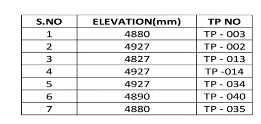
A Tie-in table must be maintained in overall General Arrangement drawings and P&ID for a better understanding of the plant interface. A Tie-In list usually consists of the Tie-in point number and elevation of the Tie-in point from the design point of view. The tie-in list can be used to estimate the cost of construction and for scheduling work well in advance of the actual piping design activity. Below is an example of a Tie-in point list table
Fig. 1: Tie-in Point Table
Types of Piping Tie-ins
There are different types of Tie-in Points
Plant Tie-In Points.
Skid Tie-In Points.
Plant Tie-In points are used for plant interface between existing plant lines or other process lines coming from a neighboring plant. The elevations should be matched with the existing plant design.
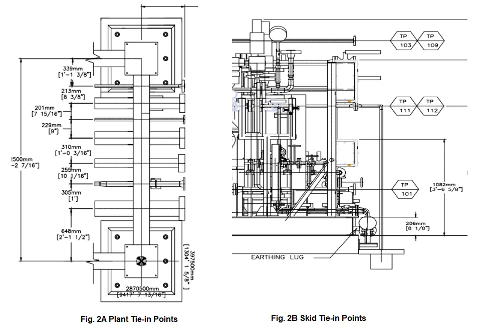
The Tie-in point flanges or isolated valves should be installed in such a way that proper spacing is maintained for operation and maintenance purposes. Please refer to Fig. 2A for plant tie-in points placed on the pipe rack.
Skid Tie-In points are located inside the plant to establish interconnecting connection piping between different skids and Equipment present in the plant. The Tie-in points are installed in such a way that it allows the process lines from other skids to be connected at a single point to ease operation and maintenance. Please refer to Fig. 2B for Skid Tie-in Points.
Fig. 2: Types of Piping Tie-ins
Again depending on the actual connection methodology, there are four types of pipe tie-in connections as mentioned below:
Buttwelded Piping Tie-in
Flanged Piping Tie-in
Threaded Piping Tie-in, and
Hot-tapped Tie-in connection
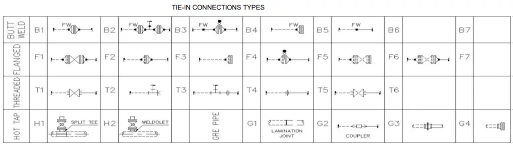
Refer to Fig. 3 below which clearly shows various types of tie-in connections used in the piping industry.
Fig. 3: Different Piping Tie-ins
Piping Tie-in Point Design Considerations
When designing and installing tie-in piping, it’s often driven by the need to handle increased flow rates in utilities or processes, which might require new equipment. Once you know the process needs and have sized the tie-in piping, the next step is to think about how to isolate the piping during installation.
Shutting down the entire plant isn’t always practical, so a brief, scheduled outage might be planned to break the line and install the tie-in. Afterward, you can install the piping while the plant operates normally. To avoid multiple shutdowns, consider adding a shutoff valve upstream of the tie-in point. This allows you to safely isolate the area and install the piping later without disrupting operations.
When choosing a valve, make sure it can handle pressure on one side while being unpressurized on the other, and that it meets safety requirements like being lockable and compliant with OSHA standards. Including a drainable spool piece downstream of the valve is smart, as it lets you check for leaks and safely relieve pressure.
Finally, consider the routing of the connecting piping. While a straight route may seem easiest, adding flexibility with jogs, loops, or flexible connectors might be better for reducing stress on sensitive equipment. Tools and software are available to help analyze and optimize the piping layout, taking into account factors like pressure, temperature, and dynamic loads. The major design considerations for tie-in piping connection are
Before considering the allocation of Tie-in points allowable Flange loading (or tie-in point displacements) should be calculated as per the standards.
Tie-in point locations should be mentioned accurately in all directions to avoid conflict with the counter connection.
Process engineers should decide on the Tie-in locations to avoid hazards during the operational time.
The Engineer who decides the Tie-In locations should have a better view of maintenance and operation. A Tie-in plot plan should be prepared and checked by the plant personnel to avoid conflict.
The valve and flange rating is considered as per the connecting line size.
The Tie-In Items (Flanges and Valves) are considered as an additional quantity when calculating the Piping MTO.
The Tie-in locations should be physically checked on the site before preparing the Tie-in Table.
Change of instrumentation or control loop doesn’t need a Tie-In Point.
Additional Drains and vents must be added as per the type and location of the Tie-ins.
The Tie-in should be placed in a location considering the pipe support locations as pipe supports are needed based on the type of Tie-in selected.
In the view of future equipment designers, the Tie-in fluid properties should be provided by the process engineer.
Different kinds of shut-off valves including ball, gate, and butterfly valves are suitable for isolation.
Based on the process fluid and pressure conditions process engineer will select the suitable valve.
A separate GA drawing must be prepared like a plot plan which shows all the Tie-in locations in the plant.
In some conditions, when there will be no possibility to isolate the Tie-in point or to shut down the plant process, an alternative method known as Hot Tapping can be considered to accommodate the line break. More details about hot tapping on operating lines are covered here.
Benefits of Piping Tie-in Connections
A Tie-In point in a piping/pipeline is a point where the pipeline is closed for further expansion or for connection with an existing pipeline. Tie-in points are usually located at the end of plant battery limits either on the pipe rack or sleeper or at the individual Equipment ends. This Tie-in is made along with the P&ID preparation considering the future need for the project
There are several benefits to using piping tie-ins in a piping system, these include:
Cost-effective: Tie-ins can be a cost-effective way to add or extend a piping system, as it eliminates the need for new construction and minimizes the need for new equipment.
Increased system efficiency: By connecting new piping to existing piping, the entire system can function more efficiently and effectively.
Minimizes downtime: Tie-ins can be done in a way that minimizes downtime and interruption to the operation of the system.
Improved safety: Tie-ins can be done in a way that improves safety by reducing the risk of leaks or other problems.
Flexibility: Tie-ins provide flexibility by allowing for easy addition or modification of the piping system.
Better maintenance: By connecting new piping to existing piping, the entire system can be easier to maintain, as any issues or problems can be identified and addressed more quickly.
Better integration: Tie-ins create a seamless integration between new and existing piping, improving the overall function and operation of the system.
It’s important to note that, despite the benefits, proper planning and execution of the tie-in is crucial to ensure safety, quality, and efficiency. The use of a detailed method statement, following proper procedures, and having a well-trained team is key to a successful tie-in.
Piping Tie-in Schedule
A piping tie-in schedule is a document (engineering deliverable usually prepared by process engineers) that outlines the plan and schedule for a piping tie-in project. It typically includes a detailed list of the tasks that need to be completed, the resources (e.g. personnel, equipment, materials) required to complete each task, and the timeline for each task. The schedule should also include milestones and deadlines, as well as contingencies in case of delays or unexpected issues.
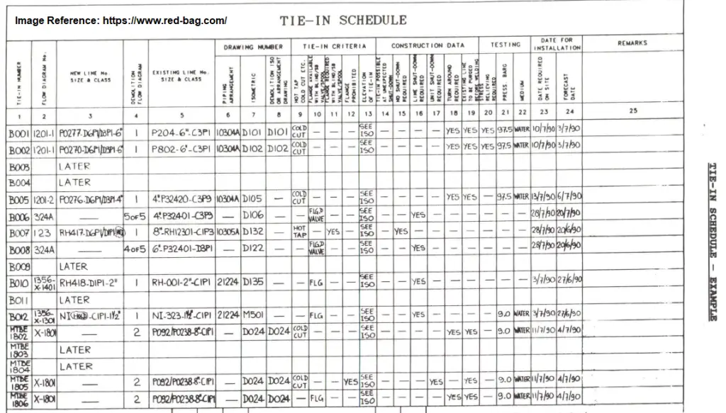
The schedule should also include safety and quality assurance plans, as well as inspection and testing requirements. The piping tie-in schedule can be used as a guide for the project team and stakeholders to track the progress of the project, identify any potential issues, and make adjustments as needed. It is also used as a tool to coordinate the different activities and ensure that all are done properly and on time. A typical Tie-in Schedule is shown in Fig. 4 below:
Fig. 4: Example of a Typical Tie-in Schedule
Safety Features for Pipe Tie-in Connection
The tie-in schedule must mention the type of work (hot work or cold work) to be used during the actual tie-in operation.
The tie-in schedule should inform if the shutdown is required for the operation to perform.
The lines to be demolished must be positively isolated, purged, and free from any hydrocarbon prior to cutting/unbolting.
The tie-in schedule must be read in conjunction with the tie-in shutdown philosophy for proper planning.
The requirement of 100% radiography for golden joints must be specifically stated.
The construction team must ensure that the existing line is isolated, depressurized, and free from hydrocarbon prior to unbolting.
Ensure that isolation valves are properly closed.
Piping Tie-in Procedure
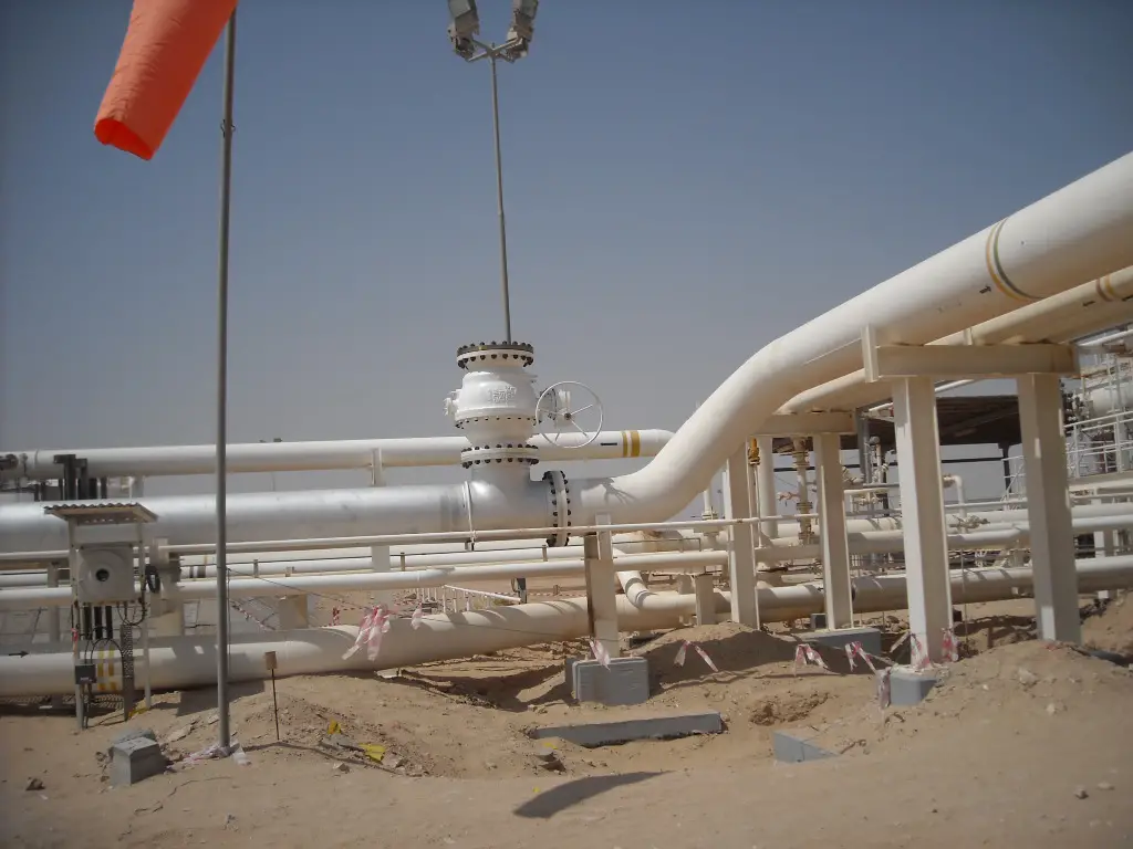
A piping tie-in procedure is a set of instructions outlining the steps that need to be taken in order to safely and effectively connect new piping to existing piping. It typically includes a detailed description of the equipment and materials that will be used, as well as the specific techniques and methods that will be employed. The procedure should also include safety precautions that need to be taken, as well as any inspection and testing requirements. Refer to Fig. 5 which shows a piping tie-in in the operating plant.
Fig. 5: Piping Tie-in for future connection
The procedure will depend on the type of tie-in and the conditions of the existing piping, but it generally includes the following steps:
Planning: This includes identifying the scope of work, gathering all necessary information and drawings of existing piping, and determining the resources required to complete the tie-in.
Preparation: This includes cleaning and prepping the existing piping and the new piping, as well as installing any necessary supports or hangers.
Tying-in: This is the actual process of connecting the new piping to the existing piping, which may include cutting, welding, brazing, or flanging, among others.
Testing and Inspection: After the tie-in is completed, the system should be tested and inspected to ensure that it is functioning properly and that there are no leaks or other issues.
Post-tie-in: This includes cleaning up the work area, restoring the site and the equipment, and updating any records or drawings.
It’s important to note that, before starting the tie-in procedure, a permit to work should be issued and safety measures should be in place. A risk assessment should also be done to identify and mitigate any potential hazards.
Construction and Installation of Piping Tie-in/ Tie-in Schedule
Before starting construction on a line break, it’s essential to issue a line break permit. This permit covers important details like the exact location of the break, the design documents needed, the type of fluid in the line, required safety equipment, potential hazards, any special cleaning or flushing needed, valve locking and tagging instructions, and a list of all involved personnel.
If the tie-in point can be isolated, you can install the connecting piping without shutting down the process. However, if isolation isn’t possible and the line can’t be shut down, a procedure called “hot tapping” is necessary. Hot tapping allows you to connect to a live, pressurized line, often used for steam, gas, water, or other utilities that must keep flowing.
The basic steps for hot tapping include welding a fitting onto the line, installing and testing a gate valve, attaching the hot tap machine, boring into the line, and then safely removing the machine after closing and locking the valve. This is a specialized task that should be done by experienced companies. After hot tapping, you can proceed with installing the connecting piping, followed by pressure and leak testing before the new piping is put into service.
The installation of piping tie-in/tie-in schedule is a multi-activity task performed as follows:
Excavation and installation of foundation (if required)
Scaffolding, Structure, Platform, Support installation
Tie-in Execution Works
Positive Isolation from Company
Blinding (Gas free line)
Cold cutting and Installation of tie-in spool
Welding, NDT, Hydrotest
Line Blowing and Drying
De-blinding and client handover
Touch-up and painting
Scaffolding removal and housekeeping
Handover to operation team/company
Piping Tie-in Method Statement
A method statement for piping tie-in is a document that outlines the specific procedures and steps that will be taken to safely and effectively connect new piping to existing piping. It is a detailed plan of the work that will be done, including the equipment and materials that will be used, the techniques and methods that will be employed, and the safety precautions that will be taken.
A typical method statement for piping tie-in would include the following information:
Introduction: A brief overview of the scope of work and the objectives of the tie-in.
Equipment and Materials: A list of the equipment and materials that will be used, including any special tools or safety equipment.
Procedures: A step-by-step description of the procedures that will be followed, including the techniques and methods that will be used to connect the new piping to the existing piping.
Safety: A description of the safety precautions that will be taken, including any specific hazards associated with the tie-in and the measures that will be taken to mitigate those hazards.
Inspection and Testing: A description of the inspection and testing that will be done after the tie-in is completed, including any acceptance criteria that must be met.
Quality Assurance: A description of the quality assurance procedures that will be followed, including any inspections or tests that will be done to ensure that the work is done to the required standards.
Emergency Procedures: A description of the emergency procedures that will be in place in case of any accidents or incidents.
It’s important to note that, before starting the tie-in, the method statement should be reviewed and approved by relevant parties, such as the safety officer, the quality manager, and the project manager.