Recent Posts

The New Version of Pipe Stress Analysis Software PASS/START-PROF 4.86 Released! Have a Look at the New Fantastic Capabilities

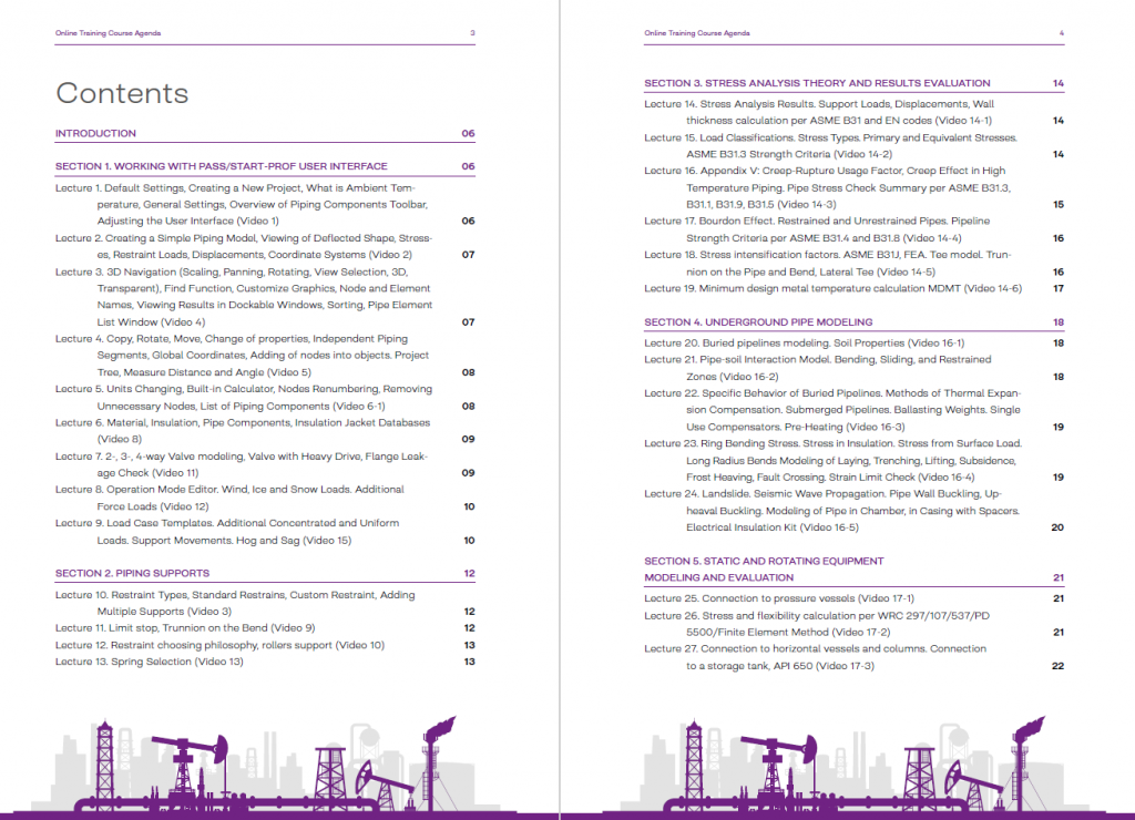
The new version of the pipe stress analysis software PASS/START-PROF 4.86 is released and can be downloaded from the official PASS website! A free 30-day trial can be downloaded here. The detailed official list of changes in PASS/START-PROF since 1965 can be found here. Available the complete pipe stress analysis training course based on PASS/START-PROF.

Have a look at the new fantastic features that PASS prepared for you.

New Codes and Code Updates

Remark: the ASME B31.3-2020 and ASME B31.1-2020 codes was incorporated in September 2021, in the previous version 4.85. PASS/START-PROF automatically calculates the stress intensification factors (i) and flexibility factors (k) following the requirements of ASME B31J – 2017

  • Updated code ASME B31.1-2022 Power Piping to the latest version
  • Updated code ASME B31.8-2020 Gas Transmission and Distribution Piping Systems to the latest version
  • Updated code ASME B31.9-2020 Building Services Piping  to the latest version
  • Updated code EN 13480-3:2017+A1:2021 Metallic Industrial Piping  to the latest version
  • Updated code SP 36.13330.2012 to the latest version
  • Updated pressure-temperature ratings for flanges to the latest version ASME B16.5-2020
  • Updated standards in databases to the latest versions: ASME B16.9-2018 (Bends, Tees, Reducers), ASME B36.19-2022, ASME B36.10-2022 (Pipes)
  • Updated wind, snow, and ice load codes to the latest versions: ASCE 7-22 (USA), IS.875.3.2015 (India), AS-NZS.1170.2:2021 (Australia/New Zeland), NBC 2020 (Canada), CFE 2020 (Mexico), GB 50135-2019 (China), SP 20.13330.2016 addenda 3
  • Added Dubai wind code 2013
  • Added Blast Load (DNV RP D101)
  • Added seismic codes: ASCE 7-22 (USA), IBC, NSR-10 (Colombia), KBC 2016 (South Korea), UBC 1997, NBC 2020 (Canada), CFE 2015 (Mexico), EUROCODE 8 EN 1998-1 (2013), TKP EN 1998-1-2011 (Belarus), IS 1893:2016 (India), AS/NZS 1170.4-2007 Amendment 1,2 (Australia), Seismic Code for Dubai 2013, SP 14.13330.2018 (Russia), GB 50011-2016 (China), SP RK 2.03-30-2017* (Kazakhstan), KMK 2.01.03-19 (Uzbekistan)
  • Added codes GOST 33962-2016, GOST 33964-2016, and GOST 33965-2016
  • An updated material database with material properties required by the late code editions

Here you can find the full list of available codes in PASS/START-PROF: pipe stress codes, equipment codes, standards for pipes, bends, tees, reducers, flanges, valves, beams, wind, snow, ice, seismic codes, constant and variable spring tables.

Pipe Stress Codes Dialog
Wind, Snow, Ice Codes Dialog

Finite Element Analysis Integration

PASS/START-PROF is now directly integrated with PASS/NOZZLE-FEM Software. It allows to automatically calculate:

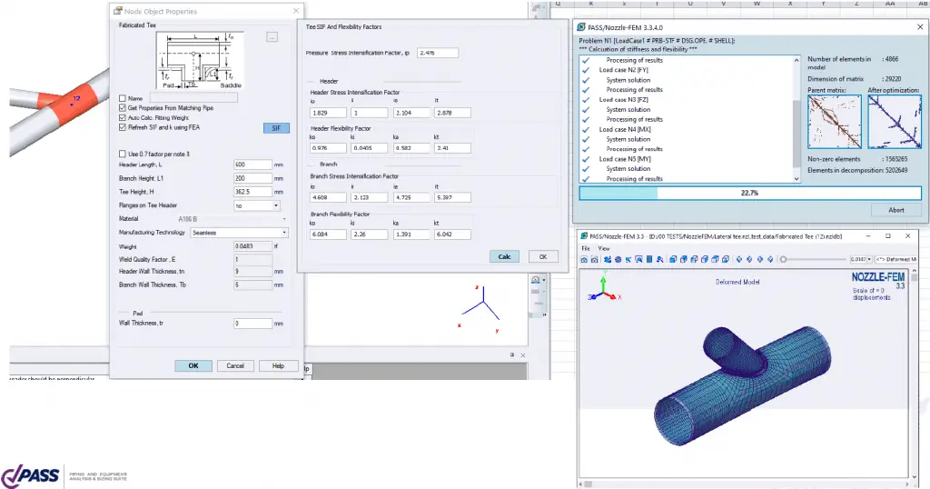
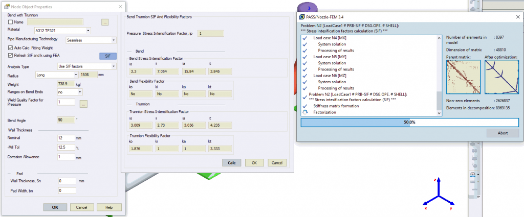
  • Stress intensification factors (i) and flexibility factors (k) for all tees, bends, and trunnions in the whole model can be automatically calculated using the finite element method (FEA) on-the-fly.
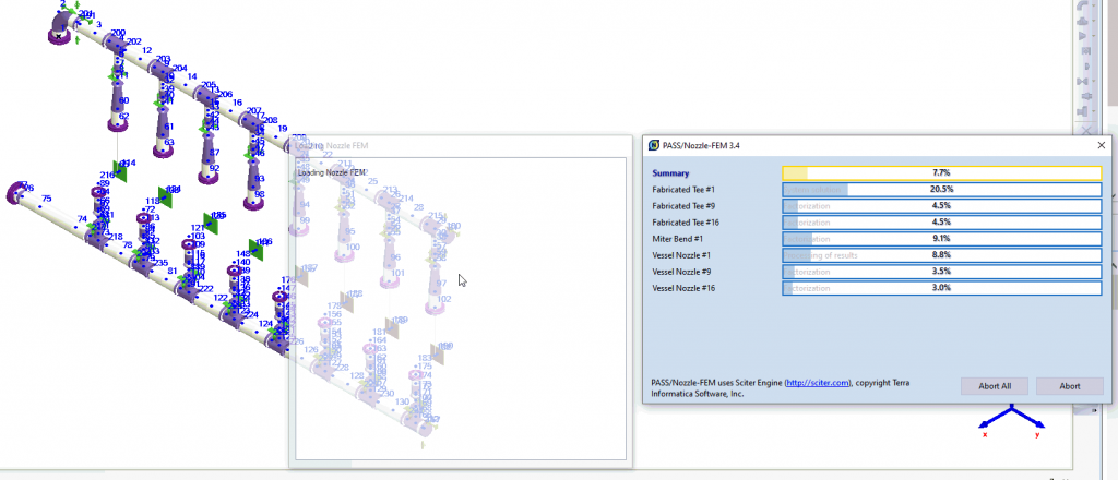
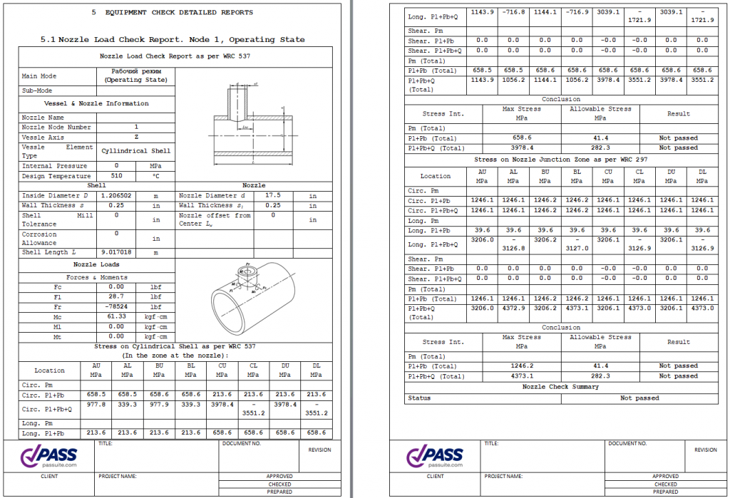
  • Vessel nozzle and tank nozzle stuffiness, allowable loads, and stresses in the nozzle-shell junction can be calculated using FEA on-the-fly automatically for all nozzles in the model.

A detailed description can be found here

Tee Object Properties with SIF and k factors are calculated automatically using FEA for lateral tee
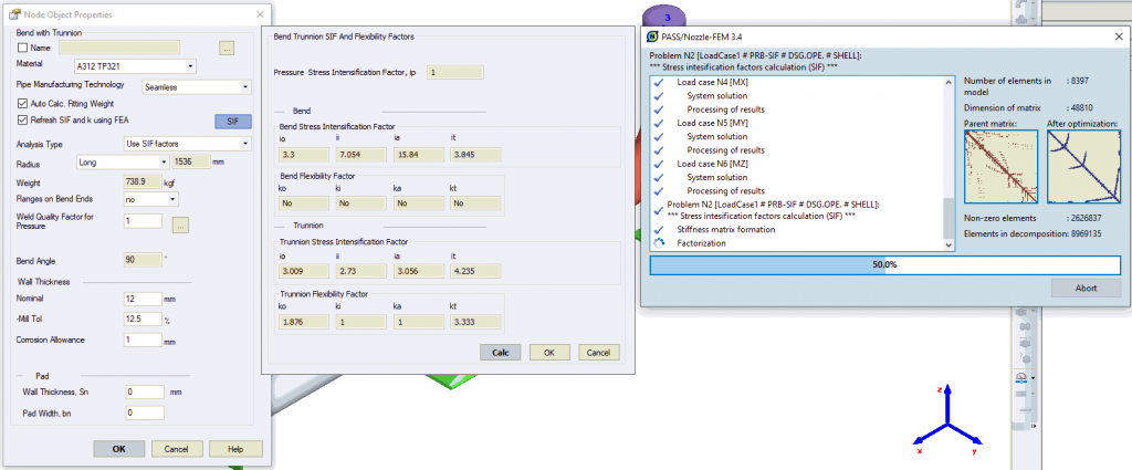
Calculation of SIF and k factors for trunnion takes about 10 seconds
This is the finite element model of trunnion created automatically from the PASS/START-PROF model
Calculation Process of SIF and k-factors for all Tees and Bends in the Model, and also Calculation of Vessel Nozzle Flexibilities and Allowable Loads

New Capabilities

Added the new MS Word report generator. It has a title page, and contents, and is generated automatically based on the templates, that can be customized. You can insert the logo of your company, change the font, layout, etc.

Added ability to model the internal restraints. Internal restraint allows for example to model the resting support which is connected to another pipe or beam element. It allows for taking into account friction, single-directional restraints, and gaps. Also, it allows modeling the pipe connection to the column, and connection to the skid, ramp, etc. Example. The pipe lies on the resting support, which is connected to the frame made of I-beams. Between the frame (node 4) and pipe (node 13), we insert a rigid element. On the rigid element at the distance of half pipe diameter, we insert node 16. In this node, we insert the internal restraint that model resting support.

Internal restraints

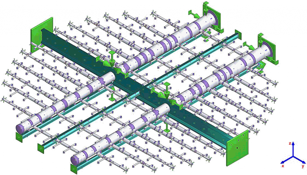
Added the new object Beam, a two-node element, that allows modeling the steel or concrete structure, working in the same model with pipes. Beam elements can have different sections: I-beam, Channel, Angle, etc. Profiles can be taken from the beam section database

PASS/START-PROF model of the FRP piping spray system in the power plant FGD tower
Skid model
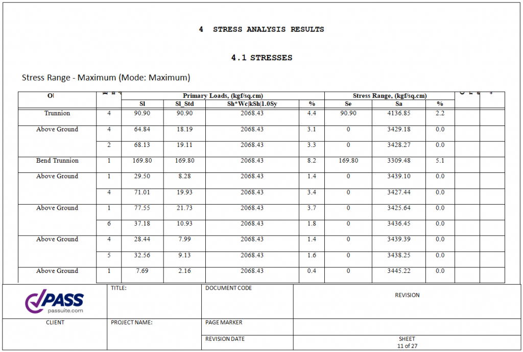
Typical Start-Prof Stress Model

Added the new object Flexible Element, a two-node element, that allows modeling the bellows or flexible hose

Modeling Flexible Element
Modeling Flexible Elements in Start-Prof

Added the new object Cone, a two-node element, that allows modeling of the reducer. It is the same as a reducer object but defined as a two-node object

Modeling a cone in Start-Prof Software

Added the new object Single Flange and Axial Coupling

Axial Coupling in Start-Prof

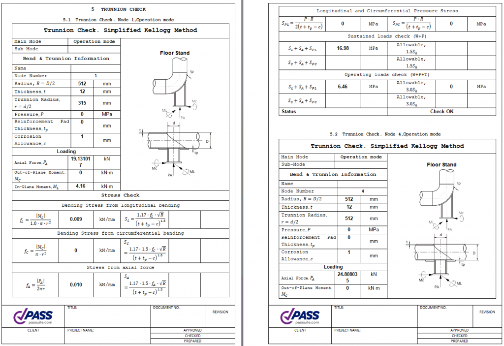
Added the new objects Trunnion on the Bend and Trunnion on the Pipe. Stresses can be analyzed using Kellogg Simplified, Kellogg Exact, or Finite Element Analysis (FEA) due to integration with PASS/NOZZLE-FEM

“Bend with Trunnion” Object Properties. SIF and k-factors Calculation Process Using Finite Element Method
Trunnion in Start-Prof

Added ability to specify the type of expansion cushions for district heating networks (soft, normal, hard)

Added ability to define the Lines. Lines can be colored and can be hidden, also hiding the stress analysis results for the hidden lines

  • For the floating window “Pipes List” added the ability to copy data into MS Excel and backward using the clipboard
  • Added the new floating window “Node List” with the ability to copy data into MS Excel and backward using the clipboard.

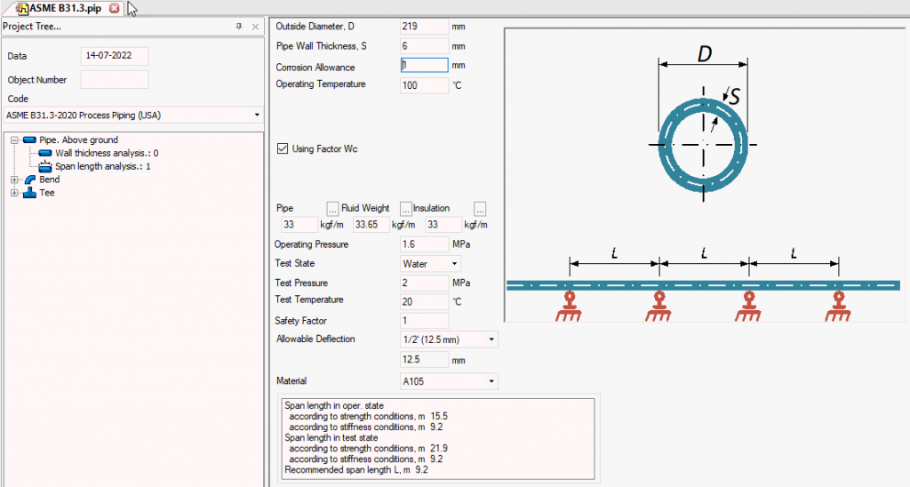
Added pipe-support spacing calculation for ASME B31.1, ASME B31.3, ASME B31.4, ASME B31.5, ASME B31.8, ASME B31.9, ASME B31.12, and some other codes

Added tee wall thickness calculation against pressure for ASME B31.1, ASME B31.3, ASME B31.4, ASME B31.5, ASME B31.8, ASME B31.9, ASME B31.12, and some other codes

Improved the Angular Expansion Joint model. Users can choose the type: gimbal or hinged. Added ability to consider the effect of the temperature on the bellows’ stiffness and allowable rotation angle. Added ability to consider the pressure and friction effect on the expansion joint stiffness

Improved the Lateral Expansion Joint model. Users can choose the type: “Lateral three or more tie-bars”, “Lateral two tie-bars pinned (plane) expansion joint”, or “Lateral two tie-bars spherical expansion joint”. Added ability to consider the effect of the temperature on the bellows’ stiffness and allowable lateral deformation. Added ability to consider the pressure and friction effect on the expansion joint stiffness

Improved the Axial expansion joint model. Added ability to consider angular and lateral stiffness automatically and automatic calculation of the equivalent axial deformation considering the rotational angle and lateral deformation

Project Tree now can be docked to the side panel

Databases

  • Increased the speed of databases operation
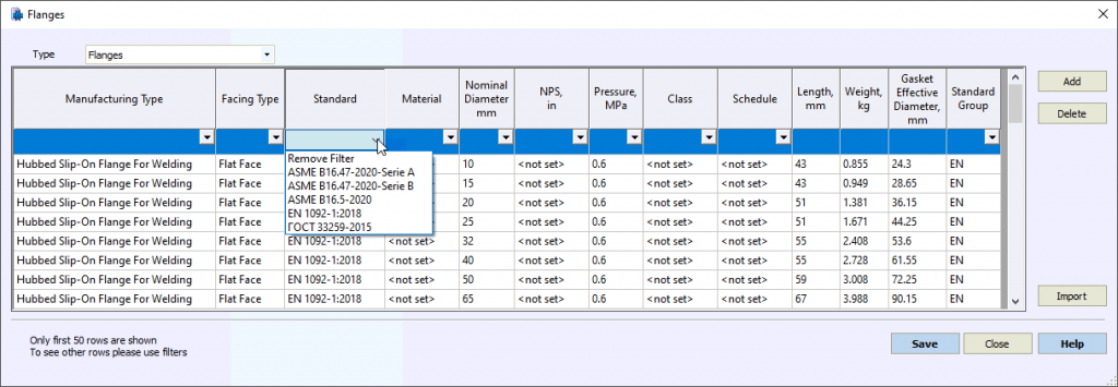
  • Added Flange Database and Single Flange Database. Included in the flange database: ASME B16.5-2020, ASME B16.47-2020 (Serie A, Serie B), EN 1092-1:2018, GOST 33259

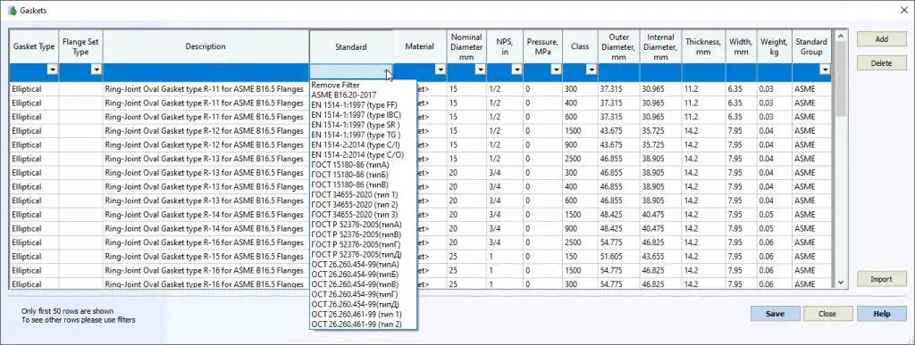
Added Gasket Database. Included in the gasket database: ASME B16.20-2017, EN 1514-1, EN 1514-2, GOST 15180, GOST 28759, GOST 52376, GOST 53561, OST 26.260.454, OST 26.260.451, etc.

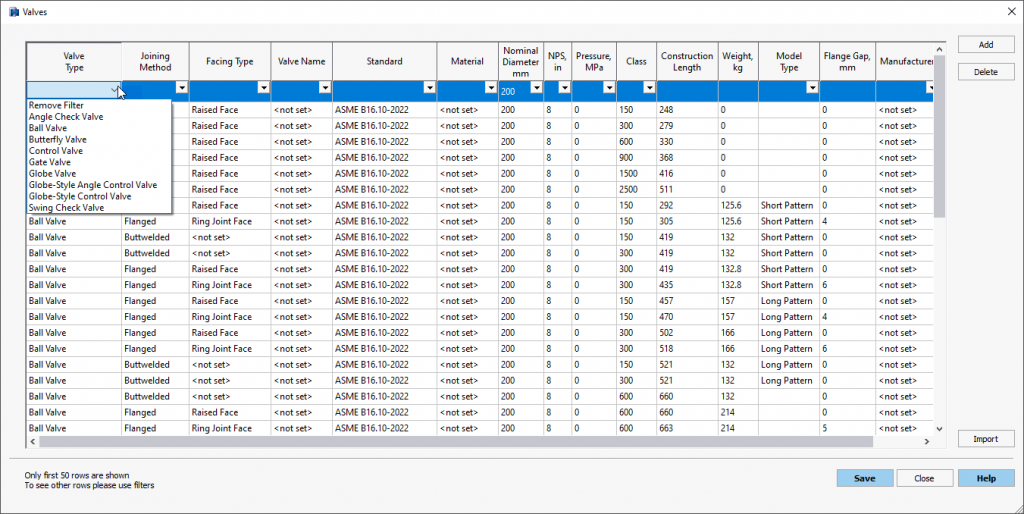
Added Valve Database as per ASME B16.10-2022

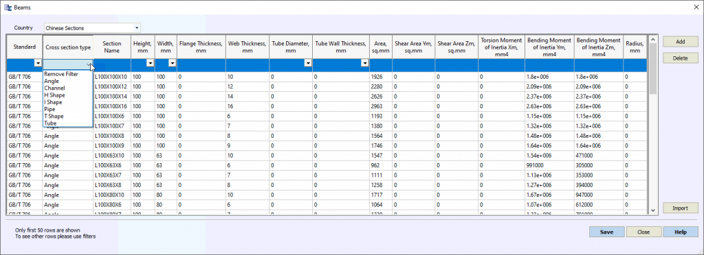
Added Beam Section Database. It contains the cross-section properties for structural beam elements

Added database with material properties for beam elements that contain AISC and Chinese sections

User Interface Changes

  • Added translation into Spanish: whole user interface, Word reports
  • Added automatic update feature. Now software can be updated automatically through the internet
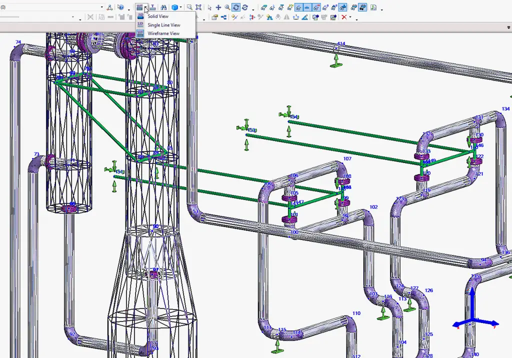
  • Added wireframe representation of the model

Added ability to select the objects using the frame with a mouse

External Interfaces

  • Added import from Autodesk Civil 3D
  • Nowadays many CAESAR II users migrate to PASS/START-PROF due to its very affordable price, very strong capabilities, and fast development that satisfy all user’s requests. To support them the import of the CAESAR II function was significantly improved. Now it is much smarter and converts much more details correctly
    • Fixed test pressure conversion
    • Added ability to open cii files created using ISOTracer
    • Added uniform loads “U” and concentrated forces “F” conversion
    • Added complex load cases conversion like “2W+2T1+1.2P1+1.3U1”-2.2U2+1.5F1
    • Added flange class, material, and code conversion
    • Added import of structural elements (beams)
  • START-AVEVA module: Added ability to import the bends with trunnions
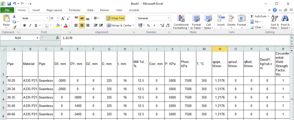
  • Added brand new import function from MS Excel. The function allows to import pipeline geometry from an Excel spreadsheet (“.xls”, “.xlsx”, “.csv”), created using one of several special templates

Added export into LICAD. In LICAD v.11 added a function to import START-PROF spring data https://www.lisega.de/en/licad/

Added export of support loads into CSV file

Training course

Role of Biologists in the Oil and Gas Sector

The scientific study of life and living beings is called biology. It can concentrate on a wide variety of topics, such as how an organism came into existence, how it is constructed, how it grows, how it works, what it does, or where it lives. A scientist who investigates the relationships between creatures and the environments in which they live is called a biologist.

It is only feasible to be knowledgeable about some aspects of the science of biology. As a result, many biologists concentrate their efforts and knowledge on a single subfield of biology and conduct in-depth research in this area. They will employ fundamental and sophisticated research techniques to collect data in the pursuit of proving or disproving ideas on the functioning of an organism.

Both macroscopic and microscopic biology are viable career paths for biologists. Objects that can be measured and observed directly are the focus of study in the field of biology known as macroscopic biology. On the other hand, to keep the items that are being researched in microscopic biology, microscopes are required. In their careers, most biologists will, at some point or another, be involved in both sorts of studies.

Fundamental research in biology aims to answer questions such as “what processes regulate the functioning of living matter?” and “why does living matter operate the way it does.” The goal of the applied research conducted by biologists is to create new or enhance existing procedures in fields such as medicine and industry.

Every subfield of biology has its unique set of responsibilities, just as every species of animal, plant, and other living things on our planet has a special role to play in the ecosystem being investigated.

Significant Responsibilities of Biologists in the Industrial Sector

The terms technician, researcher, scientist, professor, and doctor are all synonyms for the role of a worker who serves in the field of biological sciences. A biologist works in one of these capacities.

The hours worked in biology are often around the clock, although this schedule might change depending on how you construct your experiments and how long a given operation or protocol must be carried out. There is a well-laid-out plan for getting to where you want to be as a biologist, where your responsibilities will be distributed in a convoluted fashion, and where you will eventually become a regular client of natural feeds.

Before taking something on, a layperson needs to have a solid understanding of the responsibilities of biologists involved, particularly regarding the technical, scientific, and ethical aspects:

  1. A biologist will always be a student and a learner; to keep up with new information and developments in the modern world of science, biologists publish their data to make it accessible to the public. As a result, all scientists collaborate to provide valuable input.
  2. A researcher or biologist keeps the continuity of their work and lives a disciplined life to follow their experiment. This ensures that their efforts, investments of time and money, and, most importantly, their expectations are met, which ultimately contributes to their success.
  3. Before formulating any concept or proposal for a research, they had to present it in front of an esteemed senior research scientist and contend with the challenging task of making it through with the necessary level of conviction. Only after this was accomplished, were they eligible for financial assistance to carry out the research work.
  4. Given that the establishment of a laboratory and the performance of experiments are known to incur high costs for you and your nation, a biologist is required to be an excellent manager. This is necessary to ensure that financial budgeting is maintained, and that money is spent according to the various categories assigned to it. The management of the funds, in addition to research and development, is a massive burden that falls on the shoulders of a scientist. Biologists are subjected to rigorous progress reporting based on the planned proposal, and they intelligently carry out the project within the allotted amount of time, which is highly vital.
  5. As a result, a senior biologist, also known as a group leader, program leader, or principal investigator, is responsible for managing the entire group member’s research activity and financial deals. This individual is also responsible for correcting the thesis at the doctorate level, reviewing the manuscripts, and writing a good proposal. These are the real challenges to maintain in the biological world. If you don’t do any of the abovementioned things, you have no business calling yourself a biologist.
  6. To perform or accept these responsibilities, you must be a good human being, you must have a modern temperament, you must be prepared to face criticism, and you must also be prepared to offer criticism to your students or colleagues. Finally, your academic specialty will determine the entire course of your biological life.

Role of Biologists in the Oil and Gas Sector

Within the oil sector, lists serve various purposes, the most important of which is ensuring that environmental standards are followed. To conduct surveys and assist in designing mitigation for any potentially harmful impacts on habitats, the oil business employs biologists when building projects such as a pipeline.

The role of biologists is to monitor continuing activities in the oil sector to evaluate any potential influence on local animal populations, water supplies, and wetland regions. Biologists are employed in virtually every facet of the business, including oil platforms and studying how the platform’s functioning impacts the wildlife that lives there.

In some instances, the role of biologists is employed directly by the oil industry in the capacity of compliance officers. Federal and state regulatory authorities may also engage them in the span of inspectors. Contract biologists can also work for consulting businesses, which is another potential career path for them.

1.       A Technician in the Field of Biology and Science

Sometimes, a biology scientist technician will choose to specialize in habitats and wetlands, which allows them to assist in identifying wetlands that should be protected or require mitigation due to development.

The biologist may work for a private enterprise, but state or federal environmental authorities often employ them. The tasks assigned to the biologist include carrying out species surveys, writing ecological reports, and sometimes devising strategies to preserve wetland areas or making recommendations to reduce the negative impact of development on wetland areas.

2.       A hazmat technician

A hazmat technician may ensure the correct disposal of potentially hazardous materials and substances. Planning the remediation of regions that have been polluted with dangerous chemicals is another potential function that may be played.

The hazmat technician adheres to stringent regulations when cleaning up and disposing of any hazardous chemicals. The hazmat technician is also responsible for ensuring the safety of individuals working with hazardous materials.

3.       An observer of a protected species

Most of the time, protected species observers are employed by oil rigs or drillships. During seismic activities, they keep an eye out for any potential effects that might be hazardous to marine life. Observers of protected species could work directly for an oil or gas firm or a company as a consultant during activities in which there is a risk to protected species. Either way, they are employed by a business.

4.       Senior Wildlife Biologist and Conservationist

The primary emphasis of a senior wildlife biologist is on animal habitats and the influence that oil and gas development projects have on such ecosystems. A senior wildlife biologist can draft work plans for oil and gas projects or contribute to creating a design that considers animal habitats.

For instance, the scientist may devise a conservation plan that targets the area’s eagle population to reduce the likelihood of any detrimental effects being inflicted on their natural environment. As a compliance officer, the senior wildlife biologist must ensure that businesses comply with all applicable state and federal rules.

5.       Environmental Manager

Compliance officers for oil and gas businesses often work in environmental management. An ecological manager is familiar with both federal and state environmental regulations, and their job is to guarantee that the projects of oil and gas firms comply with these laws. They produce written findings, provide recommendations, and generally work to ensure businesses comply with the law.

6.       Environmental Scientist

Environmental scientists are responsible for carrying out environmental impact analyses concerning oil and gas pipeline design. Suppose environmental scientists determine that a project would significantly impact a habitat or animal species. In that case, they may provide recommendations for alternate approaches. The duties of an environmental scientist include some time spent in the field, collecting data gathered on location and time spent in the office, producing reports, and providing suggestions.

7.       Project biologist

During the construction of large-scale projects like oil pipelines, environmental regions typically undergo inspections by project biologists. A project biologist may collect data from building sites, biological areas, and wetlands.

The project biologist is responsible for producing reports and issuing permits connected to the impact the activity will have on the environment. The federal government or an oil and gas business trying to comply with national environmental standards might employ the project biologist. The federal government could also use the project biologist.

8.       On-call biologist

A biologist on call is available to assist with enforcement actions on an as-needed basis. The on-call biologist is employed by a corporation that offers its skills on a consulting basis, typically to government entities on either the state or federal level.

A biologist who is available on call may, among other things, carry out species surveys, vegetation evaluations, and bird surveys, as well as analyze ecosystems and surroundings. The on-call biologist is responsible for writing reports and assessments, taking part in compliance inspections, and obtaining permits.

Conclusion

The role of biologists in the oil and gas sector involves industrial research on a specific environment. They need to collect data regarding fossil fuels and their sustainability. The responsibilities of biologists made them a core requirement of the oil and gas industries. With them, these industries could move forward towards more sustainable ways of creating energy and providing oil and gas to the users.

FAQs

What would you say is the essential ability for a biologist to have?

  • Expertise in the field of biology.
  • To do something completely and with a lot of attention to detail.
  • The ability to do the math.

What are the five primary research areas that biologists investigate?

  • Biotechnology applied to animals
  • Biophysics.
  • The Science of Food.
  • Immunology, as well as Forensic Science.

Importance of Gasket m and y Factors

In flange leakage analysis using ASME Section VIII method, you have come across two important factors for gaskets as input. They are gasket m factors and gasket y factors. In this article, we will learn about the importance of these two factors in piping stress analysis.

What is Gasket m Factor?

Gasket m factors are known as gasket factors. The value of m is dependent on the gasket material and construction. These gasket m factor values are used as a multiplier factor for determining the necessary compressive load on the gasket to maintain a seal when the pipe is pressurized. The gasket factor m is also known as the maintenance factor. m factor is dimensionless as the values of the gasket m factor are usually calculated as the ratio of the net pressure to the internal pressure. In Caesar II software, the gasket m factor is termed the leak pressure ratio.

This constant ensures that the flange has adequate strength and available bolt load to create good sealing without leakage. At the same time, the joint will withstand the effects of hydrostatic end force or internal pressure.

Importance of Gasket Factor m

The gasket factor m is used to calculate the required bolt load for a flanged joint to work properly during the operating condition. As per ASME BPVC Sec VIII, the required bolt load in operating condition is Wm1= H + Hp = 0.785G2P + (2b x 3.14GmP)

What is Gasket y Factor?

The gasket y factor is the minimum gasket or joint‐contact‐surface unit seating load. in Caesar II software, this gasket y factor is known as gasket seating stress and the values are provided in KPa, N/mm2, or lb/in2 unit. The gasket y-factor is also an important parameter for ASME flange stress calculations and is required as an input.

Importance of Gasket y Factor

The gasket y factor is required to calculate the initial bolt load required under atmospheric temperature conditions when no internal fluid pressure is acting. The gasket must be seated properly using this minimum initial load. The initial bolt load is calculated using the formula Wm2=3.14bGy

Here,

  • G = diameter at the location of gasket load reaction
  • b = effective gasket or joint‐contact‐surface seating width
  • P = internal design pressure

Values of Gasket m and y Factors

The values of gasket m and y factors for some of the most common gasket materials and contact facings are available in Table 2-5.1 of ASME BPVC Sec VIII Div 1 code. However, note that the gasket m and y factor values are only suggested values that are proven to work satisfactorily in actual service and are not mandatory.

Gasket MaterialGasket Factor (m)Seating Stress, y (PSI)Seating Stress, y (Kpa)
Self-energizing types (O rings, metallic elastomer, and other self-sealing types)000
Elastomers without fabric or a high percent of asbestos fiber:   
Below 75A shore durometer0.500
75A or higher shore durometer12001,400
Asbestos with a suitable binder   
1/8″ thick21,60011,000
1/16″ thick2.753,70026,000
1/32″ thick3.56,50045,000
Elastomers with cotton fabric1.254002,800
Elastomers with asbestos fabric   
3 ply2.252,20015,000
2 ply2.52,90020,000
1 ply2.753,70026,000
Vegetable fiber1.751,1007,600
Spiral-wound, asbestos-filled:   
Carbon2.510,00069,000
Stainless, Monel, and nickel alloys310,00069,000
Corrugated metal, mineral fiber inserted, or corrugated metal, jacketed mineral fiber filled   
Soft aluminum2.52,90020,000
Soft copper or brass2.753,70026,000
Iron or soft steel34,50031,000
Monel or 4%-6% chrome3.255,50038,000
Stainless steels and nickel alloys3.56,50045,000
Corrugated metal:   
Soft aluminum2.753,70026,000
Soft copper or brass34,50031,000
Iron or soft steel3.255,50038,000
Monel or 4%-6% chrome3.56,50045,000
Stainless steels and nickel alloys3.757,60052,000
Flat metal, jacketed asbestos filled   
Soft aluminum3.255,50038,000
Soft copper or brass3.56,50045,000
Iron or soft steel3.757,60052,000
Monel3.58,00055,000
4%-6% chrome3.759,00062,000
Stainless steels and nickel alloys3.759,00062,000
Grooved metal   
Soft aluminum3.255,50038,000
Soft copper or brass3.56,50045,000
iron or soft steel3.757,60052,000
Iron or 4%-6% chrome3.759,00062,000
Stainless steels and nickel alloys4.2510,10070,000
Solid flat metal   
Soft aluminum48,80061,000
Soft copper or brass4.7513,00090,000
Iron or soft steel5.518,000124,000
Monel or 4%-6% chrome621,800150,000
Stainless steels and nickel alloys6.526,000180,000
Ring joint   
Iron or soft steel5.518,000124,000
Monel or 4-6% chrome621,800150,000
Stainless steels and nickel-base alloys6.526,000180,000
Gasket m and y factor values

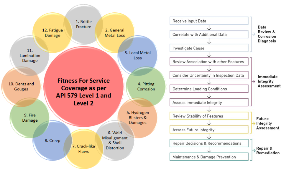
What is Fitness for Service? API 579 Fitness for Service Assessment

Fitness-for-Service (FFS) is an assessment method using the best industry practices and standards to ensure the structural integrity of any asset or component. The FFS evaluation process confirms if any asset/component is suitable for its intended purpose. Also known as Fitness for Purpose, the Fitness-for-Service assessment gives a quantitative measure of asset integrity management for the in-service components. The FFS assessment methods highlight repair or replacement needs for the asset.

The fitness for service assessment methods is used to assess the critical pressurized components and welded elements for identification of the mitigation needs to safely use the assets. Various industries such as power generation, process plants, aerospace, oil and gas, marine industry, etc make use of fitness for service methods throughout different stages of the asset’s lifecycle.

Example of Fitness for Service Assessment

Let’s understand an example of fitness for service assessment requirements. A pipeline has been transferring crude oil for the past 10 years from location A to location B with a certain pressure and temperature. Let’s assume the pipe size is 24 inches and the initial design thickness was 12 mm. During one of the inline inspections using Intelligent pigs with sensors, it detects certain anomalies such as corrosion, cracks, and dents. In most locations the anomalies are minor and within the acceptable range. However, in one location of the pipeline, it is found that the material thickness has corroded expensively and only 3 mm of material is remaining. So, the situation is very dangerous, and needs to decide whether the pipeline should be kept in operation or not. In such a situation, the Fitness for Service Assessment needs to be performed.

Similarly, Fitness-For-Service is used for numerous in-service components like Pressure vessels, Tanks, Piping Systems, Piping components, turbines, boilers, reactors, heaters, etc.

Advantages of Fitness-for-Service Assessment

Even though Fitness-for-Service is prevalent for application in the asset’s operating stage, It can be applied throughout the other life cycle stages such as the design, and fabrication. The main benefits that Fitness for Service provides are:

  • FFS is applicable in plant life management, the operating life of the asset can be increased.
  • The requirement for unnecessary repairs and replacements can be reduced a lot.
  • Fitness for Service improves plant safety.
  • The residual life of the equipment is known beforehand which increases the utilization of the asset.
  • The maintenance and inspection plan can be optimized by the prior knowledge of FFS assessment to increase plant operating time and reduce downtime.
  • Overall, reduction in capital expenditure.

Importance of Fitness for Service in Industry

For proper performance of every asset fitness for service can be a very important assessment method. The FFS is usually performed in two levels. The low-level FFS will primarily highlight if the component is fit for continued service with limited data. This is also known as screening assessment Once the item is found to be critical as per low-level FFS assessment, a high-level detailed FFS assessment can be done with more data to reliably indicate the asset’s condition.

API 579 Fitness for Service Assessment

API 579 by the American Petroleum Institute is a real boon for fitness for service assessment. API RP 579 provides guidelines to demonstrate the structural integrity assessment of the in-service degraded equipment or component. From 2007 onwards, the standard API 579 was renamed as API 579-1/ASME FFS-1 Fitness-For-Service and now comes under the purview of the API and ASME Fitness-For-Service Joint Committee.

API-579 provides clear guidelines if a piece of equipment with minor damage can be operated without replacement, repair, or reducing the pressure rating. A range of damage types such as cracks, localized corrosion, dents, creeps, blisters, weld misalignment, shell distortions, hydrogen damage, fire damage, etc is covered in the API 579 FFS assessment techniques. The fitness for service assessment tools also provides a projected remaining life and in-service margin of the asset which is very much essential for safely running the asset.

API 579 Fitness for Service Assessment Procedure

The API-579 FFS assessment procedures are detailed in the standard based on damage type and mechanism. Even though the fitness for service assessment for each type of flaw varies significantly the general FFS approach is somewhat similar which consists of the following steps:

Fitness for Service Preliminary Steps
Fig. 1: Fitness for Service Preliminary Steps
  • Flaw and Damage Mechanism Identification
  • Selecting the assessment procedure based on the applicability and limitations of the FFS assessment procedures as devised in the API 579 standard.
  • Asset Data collection (Design data, maintenance, operational history, expected future service, flaw data, material properties, etc)
  • Assessment technique finalization based on damage mechanisms present.
  • Estimating remaining life and inspection interval.
  • Devising remediation techniques to control future damage or flaw growth.
  • In-service monitoring
  • Recording all information and decisions in a proper format.

Types of Flaws and Damages in Fitness-For-Service

In Fitness for Service (FFS) assessments, various types of flaws and damage are considered to evaluate the structural integrity of equipment accurately. These flaws and damage mechanisms can arise from a combination of factors including material degradation, operational conditions, and environmental factors. Here are some common types of flaws and damage observed in industrial equipment:

  • Brittle fracture
  • Hydrogen Blisters, HIC, and SOHIC damage
  • General metal loss
  • Tank shell and edge settlement
  • Mechanical vibration
  • Thermal and mechanical fatigue
  • Local metal loss
  • The heater tube remaining life
  • Pitting corrosion
  • Hot tap thermal analysis
  • Erosion Problems
  • Hydrogen blisters and hydrogen damage
  • Weld misalignment and shell distortions
  • Local PWHT of weld repairs
  • Crack-like flaws, including creep, stress corrosion, fatigue, and corrosion-fatigue crack growth
  • Bulges and out-of-roundness distortion
  • Operation in the creep range
  • Fire damage
  • Dents, gouges, and dent-gouge combinations
  • Laminations
  • Blast loading and other dynamic effects
  • High-Temperature Hydrogen Attack
  • Wind-induced vibration of towers, stacks, and pipelines

When is Fitness-for-Service Used?

Fitness for Service (FFS) assessments are used in various scenarios across different industries to evaluate the structural integrity of equipment and determine its suitability for continued operation. Here are some common situations where Fitness for Service assessments are employed:

1. In-Service Inspection:

  • Routine Maintenance: FFS assessments are conducted as part of regular inspection and maintenance programs to monitor the condition of equipment and identify any degradation or damage that may have occurred during operation.
  • Scheduled Shutdowns: During planned shutdowns or turnarounds, FFS assessments help prioritize inspection activities and determine the extent of repairs or replacements needed to ensure equipment reliability and compliance with regulatory requirements.

Damage Assessment | Post-Failure Analysis:

  • Incident Investigation: Following equipment failures, accidents, or incidents, FFS assessments are performed to assess the extent of damage, identify the root causes, and determine the feasibility of repairing or returning the equipment to service.
  • Emergency Response: In emergencies such as leaks, ruptures, or structural failures, quick FFS assessments may be conducted to evaluate the immediate safety risks and determine the appropriate response measures.

Regulatory Compliance:

  • Compliance Audits: FFS assessments are conducted to ensure compliance with regulatory requirements, industry standards, and codes of practice governing the integrity and safety of equipment in specific industries, such as oil and gas, petrochemicals, power generation, and aerospace.
  • Regulatory Reporting: Operators may be required to submit FFS assessment reports to regulatory authorities to demonstrate the fitness for continued operation of critical equipment and obtain necessary permits or approvals.

Life Extension Study:

  • Aging Infrastructure: For aging or deteriorating infrastructure, FFS assessments help assess the remaining useful life of equipment, identify degradation mechanisms, and implement appropriate mitigation measures to extend service life and optimize asset management strategies.
  • Upgrades and Modifications: FFS assessments are conducted when implementing upgrades, modifications, or changes in operating conditions to ensure that equipment remains fit for its intended purpose and complies with safety and performance requirements.

Fitness for Service Software

Various user-friendly software packages are already available in the market for performing API 579 Fitness for Service assessment. Some of the well-known API 579 fitness for service software packages are:

  • Signal Fitness-For-Service software by the Quest Integrity group.
  • Inspect API 579-1 FFS by Codeware
  • IntegriWISE, CrackWISE, and RiskWISE fitness for service software by TWI
  • BechtFFS by Becht Engineering
  • FITest Fitness-For-Service (FFS) assessment software by Lifetech Engineering
  • α-phe FFS software by Ankaa Consulting

Codes and Standards for Fitness for Service

Even though API 579-1/ASME FFS-1 is the most widely used Fitness-For-Service standard, some other standards can be referred to. Some of these fitness-for-service codes and standards are:

  • BS 7910
  • DNV-RP-F101

Additionally, API 579 suggests to refer the following codes:

  • API-510
  • API-570
  • API-653
  • NB-23
  • ISO 16809
  • ASME B31G

Fitness for Service Training

Various renowned organizations provide Fitness for Service Engineering Training to prepare professionals suitable for those jobs. Below are some of the available FFS training courses:

  • Failure Prevention, Fitness-for-Service, Repair, and Life Extension of Piping, Vessels, and Tanks (Virtual Classroom) by the ASME
  • CSWIP Plant Inspector Levels 2/3 Module 4: Fitness-for-Service (FFS) Assessment, based on API and ASME by TWI (The Welding Institute)
  • API 579 Fitness for Service (FFS) Training Course by Wilkinson Coutts
  • Fitness-for-Service of Degraded & Damaged Tanks, Vessels, and Piping Systems following API 579-1/ASME FFS-1 and Repair Options by ASME PCC-2 course by Becht Engineering
  • Fitness-for-Service Course – Presented by Equity Engineering Group, Inc.
  • Fundamentals of Fitness for Service C137 -API 579 Certification Course by ABS group Training Solutions

This fitness for the service training course will help the candidates to

  • Analyze, evaluate, and monitor pressure vessels, piping, and tanks for continued operation
  • Explain applying the background information on fitness-for-service assessment.
  • Identify the main parts of the API/ASME standards along with annexures
  • Explain the practical application of the techniques incorporated in API 579-1/ASME FFS-1

Piping Abbreviations | Common Piping Terms

Piping abbreviations are short forms (acronyms) used to quickly and easily convey piping and related information. Abbreviated forms of various piping terms are frequently used in various piping and related engineering drawings and documents. All piping engineers should know/learn about all these abbreviations used in the piping industry to easily recognize and understand the item. In this article, we will learn some of the most frequently used common piping abbreviations.

AFC: AFC in engineering companies is an abbreviation of Approved For Construction. AFC or Approved For Construction informs that the piping drawing meets all the design requirements, and it is ready to fabricate/construct.

  • AC: Alternating Current / Air Conditioner / Air Cooler
  • AISC: AISC is an acronym for the American Institute of Steel Construction
  • ANSI: ANSI stands for American National Standards Institute Inc
  • API: The term API is very popular in Piping Industry. It is an abbreviated form of the American Petroleum Institute.
  • ASA: American Standards Association
  • Asb: Asbestos (Gaskets)
  • ASCE: American Society of Civil Engineers
  • ASHRAE: American Society of Heating, Refrigerating, and Air-Conditioning Engineers
  • ASME: The American Society of Mechanical Engineers
  • ASTM: ASTM is the short form for The American Society for Testing and Materials. More details about ASTM can be found here.
  • AWS: American Welding Society
  • AWWA: American Water Works Association

BB: The short form BB stands for Bolted Bonnet. A bolted bonnet or cover of a valve is attached to the valve body using bolts to act as a pressure-retaining shell of the valve.

BBE: BBE is an abbreviated form of Beveled Both Ends. The term BBE is widely used during purchasing of various piping and related items to denote the end condition of the item. Beveled Both Ends means that both ends are beveled. Some other related terms are as follows:

  • BOE / POE: Beveled One End / Plain One End
  • BOE / TOE: Beveled One End / Treaded One End
  • POE / TOE: Plain One End /Treaded One End
  • BLE: Bevel large end
  • BSE: Bevel small end
  • PBE: Plain Both Ends
  • TBE: Threaded Both Ends

BE: The abbreviated term BE stands for Beveled Ends. The term Beveled Ends or BE is applicable to all buttweld pipes, flanges, fittings, valves, etc. Ends are usually beveled to an angle of 30° (+5° / -0°) with a root face of 1.6 mm (± 0.8 mm).

BOM: BOM is an abbreviation of the Bill Of Materials that provides a detailed item-by-item list of the project requirements for piping or related items in a tabular format. The BOM is an important term in all engineering drawings as it specifies the items required for construction by the reference grade and standard to which it must be made, by the size and its rating. The information in this table is entirely extracted from the material take-off documents. Click here to learn more details about BOM.

BW: BW is an acronym for Butt Welding which is a circumferential butt welded joint. BW is the most common type of jointly employed in piping fabrication and is universally used to join, fittings, flanges, valves, pipes, and other equipment. Butt welding provides a high-quality and high-strength joint.

  • CAD: Computer-aided design
  • CADD: Computer-aided design drafting
  • Chk: Check valve
  • CI: Cast iron
  • Cm: Centimeter
  • Conc: Concentric
  • Cpl: Coupling
  • CRA: Corrosion Resistant Alloy
  • CS: Carbon steel, cast steel, cap screw
  • CSCC: Chloride Stress Corrosion Cracking
  • Csg: Casing
  • Csw: Concentric swage
  • Cu: Cubic
  • CWP: Cold water pressure

CMTR: CMTR or Certified Material Test Report ensures that the material is in accordance with specified requirements. The CMTR provides the actual chemical analyses, tests, and examination results.

CUI: CUI is a short form of Corrosion Under Insulation which is a type of corrosion on the external surface of insulated pipe or equipment. Even though CUI is caused by one of the multiple factors, the presence of moisture is more prevalent. Corrosion under insulation can occur in equipment and piping that are in service, out of service, or in cyclic service. More details about CUI are covered here.

  • DCCP: Design change control program
  • DCN: Design change notice
  • DIN: Deutsches Institute Normung, A German Standards Institute.
  • DIPRA: Ductile Iron Pipe Research Association
  • DIS: Ductile Iron Society
  • D&T: Drill and tap
  • D&W: Doped and wrapped (pipe)
  • DES: Double extra strong
  • DI: Ductile iron
  • Dia: Diameter
  • Dim: Dimension
  • DRL: Double Random Length (Pipe Length)
  • DSAW: Double submerged arc welded (pipe)
  • DSS: Duplex Stainless Steel
  • Dwg: Drawing

EFW: EFW is a term associated with welding which is an abbreviation of Electric Fusion Welding. Electric fusion welding is used to weld steel pipes. A directed impact kinetic energy electron beam and high-speed movement are impacted into the hot workpiece to melt the workpiece and create the weld. Hot-rolled plates are converted into pipes by the EFW method.

  • Ea: Each
  • Ecc: Eccentric
  • EJMA: Expansion Joint Manufacturers Association
  • El: Elevation (on drawing)
  • ELL: Elbow
  • Elec: Electrical
  • Eol: Elbolet
  • Esw: Eccentric swage
  • EUE: External upset ends
  • Ex.hvy: Extra-heavy
  • Ex.stg: Extra-strong
  • Exp jt: Expansion joint

ERW: ERW is the acronym for the term Electric Resistance Welded, a welding method using resistance heating to make the longitudinal weld. For better control and consistency, high-frequency induction heating is used.

ESD: ESD is an abbreviation for Emergency Shutdown which is a process incident. ESD valve or Emergency Shutdown Valve is an actuated valve designed to stop the flow of a hazardous fluid or external hydrocarbons when a dangerous event is detected. ESD valves are the final defense against process hazards.

  • FAB: Fabricate/fabricator
  • FAS: Free along-side
  • FC: Fail Close for Control Valve
  • FCI: Fluid Controls Institute
  • F&D: Faced and drilled (flanged)
  • FE: Flanged ends/flow element
  • FF: Flat Face (Flange)/ Full face
  • F/F: Face of flange
  • Fig: Figure (number)
  • FMA: Forging Manufacturers Association
  • FO: Fail Open for Control Valve
  • FOB: Flat On Bottom (terminology for Eccentric Reducer)/ Free on board.
  • FOT: Flat On Top (terminology for Eccentric Reducer)
  • FSD: Flat side down
  • FSU: Flat side up
  • FPT: Female Pipe Thread
  • FRP: Fiber Reinforced Pipe (Composite pipe material). Click here to learn more details about FRP Piping.
  • Flex: Flexitallic (gasket brand name)
  • Flg.: Flange
  • Flgd: Flanged ends/flow element
  • FS: Forged steel
  • Ft: Feet/foot
  • FW: Field weld/fire water
  • FFL: Finished Floor Level

FFS: FFS is an abbreviation of Fitness For Service which is a method for assessing the integrity of in-service equipment and items. Assessing fitness-for-service improves plant safety and operational performance by avoiding unnecessary replacements and repairs. More details about FFS are explained here.

FFW: FFW is an abbreviated form of Field Fit Weld that indicates that a field adjustment welding in the piping may require the addition of an extra length of pipe.

  • Gal: Gallon
  • Galv: Galvanised
  • GG: Gauge glass
  • GJ: Ground joint (union)
  • Glb: Globe (valve)
  • GMAW: Gas Metal Arc Welding
  • GR: Grade
  • Gsk: Gasket
  • GOST: Gosstandart of Russia
  • GPM: Gallons per minute
  • GPS: Gallons per second
  • GTAW: Gas Tungsten Arc Welding

HAZ: HAZ stands for Heat-Affected Zone. This term is frequently used in welding, cutting, and other joining processes that involved intense heat. In the HAZ, severe heating causes microstructural and metallurgical changes in the metal. Details about Heat Affected Zone are covered here.

  • HB: Brinell Hardness
  • HRC: Rockwell C Hardness
  • HC: Hose coupling
  • HC: Heat Conservation Insulation
  • Hdr: Header
  • Hex: Six-sided (Hexagonal) head, bolt, plug, etc.
  • HI: Hydraulic Institute
  • HN: Heat number
  • HVAC: Heating, ventilating, and air conditioning
  • Hvy: Heavy
  • HPP: Highest point of Paving

ISBL: ISBL is a short form for In-Side Battery Limits. ISBL is decided based on the function and denotes the equipment and components solely dedicated to a single process. They are usually located within a geographical limit.
ITP: ITP stands for Inspection Test Plan which is an important document covering the construction quality control plan. All the inspections and tests required to maintain the quality of the product/item are usually mentioned in the ITP document.

  • IBBM: Iron body bronze mounted (valve)
  • ID: Inside diameter
  • IPS: Iron pipe size
  • IS&Y: Inside screw & yoke (valve)
  • ISO: Isometric (drawing)
  • ISO: International Standards Organizations
  • IUE: Internal upset ends
  • ISRS: Inside Screw Rising Stem
  • ISNRS: Inside Screw Non-Rising Stem
  • Jkscr: Jack screw
  • JIS: Japanese Industrial Standard
  • Jt (s)/ Jt.: (joints)
  • JW: Jacket water
  • Kg: Kilogram
  • LC: Locked closed
  • LO: Locked open

LR: LR is an abbreviation of Long Radius Elbow. There are two types of elbows, long radius and short radius depending on the center-to-face dimension. For long radius elbow, the center-to-face dimension is 1.5 times the Nominal pipe size (1.5D) whereas the same for short radius elbow is 1D.

MAOP: MAOP is a very useful term for the process and mechanical design of equipment. It is an abbreviated form for Maximum Allowable Operating Pressure. The Maximum Allowable Operating Pressure or MAOP is the maximum pressure, that a piece of equipment or piping can safely operate.

MTO: MTO is the abbreviated form of Material Take-Off, an important term used in piping materials engineering to estimate the number of required piping items in any project. Refer to https://whatispiping.com/piping-mto/ for further details.

  • NBR: Nitrile Butadiene Rubber
  • NDE: Non-Destructive Examination or NDE is also popular as Non-Destructive Testing. Typical examples of NDE are MPI, Ultrasonic Testing, Liquid Penetrant Testing, etc.
  • NPS: Nominal Pipe Size.
  • NPT: National Pipe Thread Tapered
  • NC: Normally closed (Valve)
  • NO: Normally Open (Valve)
  • NRS: Non-Rising Stem
  • NEMA: National Electrical Manufacturers Association
  • NFPA: National Fire Protection Association
  • OSBL: Outside Side Battery Limits
  • OS&Y: Outside Screw & Yoke
  • OD: Outside Diameter
  • OSHA: Occupational Safety and Health Act, or Administration
  • PBE: Plain Both Ends
  • PCD: Pitch Circle Diameter
  • PE: Plain End
  • PED: Pressure Equipment Directive. Click here to know more details about PED.
  • POE: Plain One End
  • PFD: Process Flow Diagram
  • PI: Pressure indicator
  • PIV: Post indicator valve
  • PMI: Positive Material Identification.
  • PWHT: Post Weld Heat Treatment.
  • PN: Nominal Pressure (metric)
  • PO#: Purchase order or number
  • P-T: Pressure – Temperature
  • PRV: Pressure Reducing Valve
  • PSV: Pressure safety (relief) valve
  • PFI: Pipe Fabrication Institute
  • PFMA: Pipe Fittings Manufacturers Association
  • PPI: Plastic Pipe Institute
  • ppm: Parts per million
  • P&ID: Piping and instrumentation diagram
  • PLE: Plain large end
  • PSE: Plain small end
  • psi: Pounds per square inch
  • psig: Pounds-force square inch, gauge
  • PVC: Polyvinyl chloride
  • PW: Potable water
  • RF: Raised face (for flanges)
  • RF Pad: Reinforcement PAD
  • RFC: Released For Construction.
  • RTJ: Ring type joint (flanges)
  • RED: Reducer
  • RAD: Radius/Radian
  • RC: Rockwell hardness scale C
  • RWMA: Resistance Welding Manufacturers’ Association
  • RPM: Revolutions per minute
  • Reqn: Requisition
  • SAW: Submerged Arc Welding.
  • SC: Sample Connection
  • SCC: Stress Corrosion Cracking
  • SCE: Safety Critical Equipment/Element
  • SCH: Schedule.
  • SDSS: Super Duplex Stainless Steel
  • SIV: Service isolation valve
  • SMAW: Shielded Metal Arc Welding
  • SMLS: Seamless pipe or fitting
  • SMYS: Specified Minimum Yield Strength
  • SO: Slip on (Flange)
  • Spec: Specification
  • SR: Short Radius Elbow
  • SRL: Single Random Length (Pipe Length)
  • SS: Stainless Steel
  • STD: Standard
  • SW: Socket Weld
  • SWE: Socket Weld End
  • SWG: Swage
  • SS. NO: Safety Shower & Eye Batch No
  • TBE: Threaded Both Ends.
  • TBE: Technical Bid Evaluation
  • TYP: Typical
  • TIG: Tungsten Inert Gas (Welding)
  • ToFG: Time of Flight Diffraction (Ultrasonic Testing)
  • TOS: Top Of Steel
  • TSA: Thermally Sprayed Aluminum
  • UNC: Unified Coarse Thread
  • UNF: Unified Fine Threads
  • UNS: Unified Numbering System
  • VMA: Valve Manufacturers Association
  • WCB: Wrought Carbon grade B
  • WPQ: Welder Performance Qualification.
  • WPS: Welding Procedure Specification
  • WN: Weld Neck (Flange)
  • WRC: Welding Research Council
  • WT: Wall Thickness
  • XS: Extra Strong
  • XXS: Extra Extra Strong/Double Extra Strong

Desalination: Overview of the Reverse Osmosis Process

A desalination plant is a facility that converts salt water from the sea into water suitable for human consumption, as well as for industrial or irrigation purposes. Desalination can be achieved by two types of processes: thermal or transmembrane. Semi-permeable membrane desalination is the most widely used technology in the industry because it requires much less energy than thermal desalination and is therefore more cost-effective.

This article will focus on this second type. This is the most widely used reverse waterproofing process in use today in many countries around the world.

The high demand for drinking water and the high energy potential available have enabled the development of sustainable methods of energy production based on seawater desalination, making it an increasingly attractive and necessary technology. There are several technologies used on an industrial scale to desalinate seawater. Among all the technologies, seawater reverse osmosis is the most widely used worldwide.

It is now a mature technology and can be found in many coastal areas of the world where natural water resources are limited. Advances in research and development related to this technology are ongoing. One of the latest innovations aims to significantly reduce energy consumption and minimize adverse effects on membranes.

Reverse Osmosis Process Description

To understand the purpose and process of reverse osmosis, we must first understand the natural process of osmosis.

Osmosis is a natural phenomenon. It is one of the most important processes in nature and occurs when two solutions with different solute concentrations are separated by a semi-permeable membrane (allowing only the solvent to pass through). This phenomenon occurs spontaneously without any energy input.

Thus, two solutions with different salt concentrations tend to equalize their concentrations. The solvent from the lower-concentration solution tends to flow through the semi-permeable membrane into the higher-concentration solution until the concentration is uniform.

The driving force of this solvent flow depends on the osmotic pressure and is related to the difference in solute concentration between the two solutions. Specifically, it is defined as the equilibrium pressure that is established between solution and solute. Therefore, the osmotic pressure of a pure solvent is zero. When equilibrium is established between two solutions of different concentrations, the equilibrium pressure is equal to the osmotic pressure difference.

The process of reverse osmosis involves osmosis in the opposite direction. Osmosis occurs spontaneously without energy, so energy must be supplied to make it occur in the opposite direction.

Solvent transfer occurs from the concentrated solution to the more dilute solution. Reproducing this phenomenon in seawater on an industrial scale requires a pump (needed to generate pressure) and a semi-permeable membrane to allow the solvent to pass through.

A reverse osmosis membrane is a semi-permeable membrane that allows water molecules to pass through, but not various compounds that are not required for the end use of the water. In addition, it can also contain bacteria.

The buoyancy must be higher than osmotic for the water to be desalinated. When the concentrated solution is pressurized, water molecules pass through the semi-permeable membrane while contaminants are retained.

A desalination plant can be divided into four stations.

  • Pumping, storage, and screening.
  • Pre-treatment and high-pressure pump
  • Process: Reverse Osmosis.
  • Post-treatment

Seawater Pumping

Seawater recovery systems for desalination plants include open or closed intakes.

Open water intakes draw water directly from the sea. They are the most vulnerable to overflows and, for obvious reasons, present a higher risk of contamination. Therefore, the quality of the water obtained may vary.

In contrast, water from a closed intake (a well) is not an inexhaustible source of water, and although it is more uniform and of higher quality, it can be assumed that its capacity decreases significantly with relative frequency.

Thus, from the point of view of flow assurance, the open intake has an obvious advantage, as the difficulty of securing the production flow in well water is high.

A disadvantage of large-capacity plants is that they require large areas for permeable marine boreholes, which limits the supply rate. Therefore, the first step in the water treatment process is to pump water from the natural environment to the plant.

If the natural soil is not suitable, water must be pumped to the plants. The function of the pumping station is to send water to the desalination plant. The factor that ensures this pressure peak for the water supply to the plant is the hydraulic pump, whose operating point is determined by the flow rate required for the installation process as well as the pressure.

Reverse Osmosis Process Steps
Fig. 1: Reverse Osmosis Process Steps

Pre-treatment

Reverse osmosis desalination requires a very thorough pre-treatment of the seawater to prevent suspended solids from settling on the membrane. This rapidly reduces the flux produced.

The purpose of pre-treatment is varied. First, it keeps the module free of blockages from suspended solids, microorganisms, and salt deposits, among others. On the other hand, the water must be given characteristics compatible with the nature of the membranes: chlorine content, pH, temperature, etc.

Depending on the type of reverse osmosis module, all particles larger than 10-50 µm must be retained. This is done by using coarse pre-filtration followed by sand filtration to remove larger suspended solids.

Subsequently, biocide treatment and acidification are required to prevent microbial growth on the membrane and to avoid carbonate precipitation. Finally, the cartridge filtration method can retain particles as small as tens of microns, which cannot be retained by sand filters.

The process used is appropriately selected according to the water quality of the feed water. Nowadays, the removal of contaminants by ultrafiltration (UF) membranes is the most widely used process, as it offers the best balance between contaminant removal and product penetration. The main pre-treatment steps are:

  • – Chlorination
  • – Clarification: Coagulation Flocculation Sedimentation
  • – Prevention of scaling
  • – Discolouration – Cartridge filtration

These procedures are carried out using self-cleaning filters, ultrafiltration, and chemical dosing systems.

  • Ferric chlorine: Coagulation of small particles at the UF inlet.
  • Sulphuric acid: UF and RO washing systems
  • Bisulfite: Chlorine neutralization at the RO inlet.
  • Antiscalant: Prevents precipitation on RO membranes.
  • Sodium hypochlorite: Drinking water tank disinfection
  • Sodium hydroxide: PH adjustment for drinking water

A high-pressure pump pumps seawater into the RO module where the membrane is located.

Desalination and energy recovery.

At this point, the water has already gone through all the preliminary pre-treatment stages, where it underwent Physicochemical conditioning to minimize the risk of blockages in the desalination equipment due to the precipitation of poorly soluble salts and the accumulation of suspended particles. It has also been conditioned to balance its mineral content and reduce its highly corrosive nature.

Before entering the reverse osmosis membrane, the treated seawater is pressurized with a high-pressure pump, typically between 45 and 90 bar, depending on the temperature and salinity of the water. At this point, it is possible to separate the salts by obtaining a stream of potable water on one side and what is known as “reject” on the other. Pumps are used to increase the transmembrane pressure.

Pumps are used to increase the transmembrane pressure. Pumps or an agitation system allow the water to be treated to circulate within or between the modules. Separation is achieved in the membrane modules.

Two types of systems can be distinguished, depending on how the transmembrane pressure is applied.

Pressure filter system

A basic reverse osmosis desalination system consists of a high-pressure pump feeding brine to a set of spirally wound membranes. The substance enters the membrane and exits the assembly without pressure, while the concentrate is kept under pressure by a pressure regulating valve and finally exits the system when it is opened.

Submerged membrane systems

Semi-permeable reverse osmosis membranes for seawater treatment are usually made of polyamide compounds, but some also use cellulose acetate.

Polyamide membranes are characterized by a higher specific water content and a higher salt-holding capacity than cellulose acetate membranes. Polyamides are stable over a wide pH range but are susceptible to oxidative degradation by chlorine.

Semi-permeable membranes are used to withstand various working pressures in the industry and must be arranged according to specifications.

The production capacity of a desalination plant is obtained by installing several basic production units or modules in parallel. Thus, a module is nothing more than a set of membranes of a specific configuration that form the basic unit to produce permeate water.

Energy recovery

A reverse osmosis plant uses a large amount of energy to reach the pressure levels required for the process. This stage of the desalination plant consumes the most energy.
The pressure drop across the reverse osmosis membrane is approximately 1.5-2 bar, depending on the number of cells per pressure pipe. As mentioned, reverse osmosis desalination generally converts only 45% of the energy used into a pure water stream, and the rest is discarded as a high-pressure waste stream.

Thanks to the energy recovery system, it is possible to reuse the energy from this stream. This stream is sent to an energy recovery system, which transfers its energy directly to a part of the water supply.

There are two main concepts in energy extraction.

Turbine:

Driven by the high-pressure waste stream exiting the diaphragm, it rotates a shaft connected to a high-pressure pump motor, which reduces the amount of electrical energy required to pressurize the feed stream of the osmosis process.
Pressure exchange:

Uses the positive displacement principle to pressurize seawater in direct contact with saltwater by removing the reverse osmosis membrane.

The water removed by reverse osmosis is sent to the PX unit, where its pressure is transferred directly to a part of the water supply with an efficiency of more than 95 %. This feed water leaves the controlled heat recovery unit and passes through a booster pump to compensate for hydraulic losses in the piping, the heat recovery unit, and the membrane.

Seawater flows to the outlet of the high-pressure pump but does not pass through it. This is important because the high-pressure pump can be sized to pump only a flow rate equal to the sorbent volume instead of the entire feed stream, as well as reducing the electrical energy required.

Pressure exchangers increase the efficiency of desalination plants by harnessing waste energy. By pressurizing part of the water supply, high-pressure pumps can be downsized by up to 60 %. This not only saves energy consumption but also capital investment costs.

Reverse Osmosis Principle

The reverse osmosis process, as explained above, consists of making the solvent (water) pass through the semi-permeable membrane from the side where the most concentrated solution is (seawater, with dissolved salts) to the opposite side, without the salts passing through, by exerting pressure on the liquid.

This pressure depends on the degree of desalination to be achieved. In this way, you get two flows. One is a low salinity flow called “permeate” and the other is a high salinity flow called “reject”.

It should be remembered that during the phenomenon of osmosis, only water molecules from the low-concentration solution spontaneously cross the membrane to bind to the high-concentration water to restore the balance of concentrations.

This is followed by the phenomenon of reverse osmosis or hyperfiltration, where pressure is applied to the new concentrated solution to “force” the water through the membrane. This process produces fresh water with very good results, as the membrane retains between 95% and 100% of the particles in the water. This percentage varies depending on the quality of the membrane.

Post-treatment

In most cases, all or part of the produced water is intended for human consumption and must comply with local drinking water regulations. Further processing (ion exchange, electro-deionization) is required.

Some countries do not have quality standards for drinking water. In such cases, the recommendations of the World Health Organisation (WHO) can serve as a reference for the international community. The WHO classifies drinking water quality standards into five groups. Those of interest to the desalinated water producer relate to:

Physical properties: temperature, clarity, odor, suspended solids (SS) content. Chemical properties: salinity, chlorine, pH, etc.

For each criterion, the WHO assigns a guideline value. A key factor in desalination is the desired final salinity. However, sometimes more specific criteria are required, such as B, Br, and heavy metal content, and may require adjustment or further treatment.

At this point, enrichment of the end-use water is sought through remineralization. This can be:

Remineralization by addition of CaCl2 and NaHCO3

This method essentially consists of adding a solution of sodium bicarbonate and calcium chloride directly to the permeate in well-defined doses to obtain equilibrium water. Remineralization by this method is easy and fast, but the conservation of the product is problematic. In large plants, this remineralization process requires large quantities of reagents. This requires the provision of sufficient reagents and space to ensure that these products are not exhausted.

Remineralization by passage through a calcite bed

In this remineralization process, water is filtered through the calcite layer from the bottom up and the resulting water is remineralized. Remineralization by this method is effective, simple, and therefore easy to operate.

Remineralization of infiltrated water by the addition of Ca(OH)2

The osmosis water (the permeate) is remineralized by injecting the prepared Ca(OH)2 lime water into a lime solution to obtain balanced water.

Water storage and waste disposal

Drinking water produced in factories must be stored in buffer water tanks upstream of the municipal water distribution network. On the other hand, the discharged water can be further treated and discharged into the sea, minimizing the impact.

Further Studies and Online Video Courses

If you still have queries, the following video courses will surely give you an enhanced experience: