Piping abbreviations are short forms (acronyms) used to quickly and easily convey piping and related information. Abbreviated forms of various piping terms are frequently used in various piping and related engineering drawings and documents. All piping engineers should know/learn about all these abbreviations used in the piping industry to easily recognize and understand the item. In this article, we will learn some of the most frequently used common piping abbreviations.
AFC: AFC in engineering companies is an abbreviation of Approved For Construction. AFC or Approved For Construction informs that the piping drawing meets all the design requirements, and it is ready to fabricate/construct.
- AC: Alternating Current / Air Conditioner / Air Cooler
- AISC: AISC is an acronym for the American Institute of Steel Construction
- ANSI: ANSI stands for American National Standards Institute Inc
- API: The term API is very popular in Piping Industry. It is an abbreviated form of the American Petroleum Institute.
- ASA: American Standards Association
- Asb: Asbestos (Gaskets)
- ASCE: American Society of Civil Engineers
- ASHRAE: American Society of Heating, Refrigerating, and Air-Conditioning Engineers
- ASME: The American Society of Mechanical Engineers
- ASTM: ASTM is the short form for The American Society for Testing and Materials. More details about ASTM can be found here.
- AWS: American Welding Society
- AWWA: American Water Works Association
BB: The short form BB stands for Bolted Bonnet. A bolted bonnet or cover of a valve is attached to the valve body using bolts to act as a pressure-retaining shell of the valve.
BBE: BBE is an abbreviated form of Beveled Both Ends. The term BBE is widely used during purchasing of various piping and related items to denote the end condition of the item. Beveled Both Ends means that both ends are beveled. Some other related terms are as follows:
- BOE / POE: Beveled One End / Plain One End
- BOE / TOE: Beveled One End / Treaded One End
- POE / TOE: Plain One End /Treaded One End
- BLE: Bevel large end
- BSE: Bevel small end
- PBE: Plain Both Ends
- TBE: Threaded Both Ends
BE: The abbreviated term BE stands for Beveled Ends. The term Beveled Ends or BE is applicable to all buttweld pipes, flanges, fittings, valves, etc. Ends are usually beveled to an angle of 30° (+5° / -0°) with a root face of 1.6 mm (± 0.8 mm).
- Bbl: Barrel
- Bdr: Bleed ring
- Bfy: Butterfly (valve)
- BL: Battery Limit / Boundary Limit
- Bld: Blind (flange)
- Bld: Spectacle blind (blate between flanges)
- BOP: Bottom of pipe
- BOQ: Bill of Quantity
- Brz: Bronze (valve)
BOM: BOM is an abbreviation of the Bill Of Materials that provides a detailed item-by-item list of the project requirements for piping or related items in a tabular format. The BOM is an important term in all engineering drawings as it specifies the items required for construction by the reference grade and standard to which it must be made, by the size and its rating. The information in this table is entirely extracted from the material take-off documents. Click here to learn more details about BOM.
BW: BW is an acronym for Butt Welding which is a circumferential butt welded joint. BW is the most common type of jointly employed in piping fabrication and is universally used to join, fittings, flanges, valves, pipes, and other equipment. Butt welding provides a high-quality and high-strength joint.
- CAD: Computer-aided design
- CADD: Computer-aided design drafting
- Chk: Check valve
- CI: Cast iron
- Cm: Centimeter
- Conc: Concentric
- Cpl: Coupling
- CRA: Corrosion Resistant Alloy
- CS: Carbon steel, cast steel, cap screw
- CSCC: Chloride Stress Corrosion Cracking
- Csg: Casing
- Csw: Concentric swage
- Cu: Cubic
- CWP: Cold water pressure
CMTR: CMTR or Certified Material Test Report ensures that the material is in accordance with specified requirements. The CMTR provides the actual chemical analyses, tests, and examination results.
CUI: CUI is a short form of Corrosion Under Insulation which is a type of corrosion on the external surface of insulated pipe or equipment. Even though CUI is caused by one of the multiple factors, the presence of moisture is more prevalent. Corrosion under insulation can occur in equipment and piping that are in service, out of service, or in cyclic service. More details about CUI are covered here.
- DCCP: Design change control program
- DCN: Design change notice
- DIN: Deutsches Institute Normung, A German Standards Institute.
- DIPRA: Ductile Iron Pipe Research Association
- DIS: Ductile Iron Society
- D&T: Drill and tap
- D&W: Doped and wrapped (pipe)
- DES: Double extra strong
- DI: Ductile iron
- Dia: Diameter
- Dim: Dimension
- DRL: Double Random Length (Pipe Length)
- DSAW: Double submerged arc welded (pipe)
- DSS: Duplex Stainless Steel
- Dwg: Drawing
EFW: EFW is a term associated with welding which is an abbreviation of Electric Fusion Welding. Electric fusion welding is used to weld steel pipes. A directed impact kinetic energy electron beam and high-speed movement are impacted into the hot workpiece to melt the workpiece and create the weld. Hot-rolled plates are converted into pipes by the EFW method.
- Ea: Each
- Ecc: Eccentric
- EJMA: Expansion Joint Manufacturers Association
- El: Elevation (on drawing)
- ELL: Elbow
- Elec: Electrical
- Eol: Elbolet
- Esw: Eccentric swage
- EUE: External upset ends
- Ex.hvy: Extra-heavy
- Ex.stg: Extra-strong
- Exp jt: Expansion joint
ERW: ERW is the acronym for the term Electric Resistance Welded, a welding method using resistance heating to make the longitudinal weld. For better control and consistency, high-frequency induction heating is used.
ESD: ESD is an abbreviation for Emergency Shutdown which is a process incident. ESD valve or Emergency Shutdown Valve is an actuated valve designed to stop the flow of a hazardous fluid or external hydrocarbons when a dangerous event is detected. ESD valves are the final defense against process hazards.
- FAB: Fabricate/fabricator
- FAS: Free along-side
- FC: Fail Close for Control Valve
- FCI: Fluid Controls Institute
- F&D: Faced and drilled (flanged)
- FE: Flanged ends/flow element
- FF: Flat Face (Flange)/ Full face
- F/F: Face of flange
- Fig: Figure (number)
- FMA: Forging Manufacturers Association
- FO: Fail Open for Control Valve
- FOB: Flat On Bottom (terminology for Eccentric Reducer)/ Free on board.
- FOT: Flat On Top (terminology for Eccentric Reducer)
- FSD: Flat side down
- FSU: Flat side up
- FPT: Female Pipe Thread
- FRP: Fiber Reinforced Pipe (Composite pipe material). Click here to learn more details about FRP Piping.
- Flex: Flexitallic (gasket brand name)
- Flg.: Flange
- Flgd: Flanged ends/flow element
- FS: Forged steel
- Ft: Feet/foot
- FW: Field weld/fire water
- FFL: Finished Floor Level
FFS: FFS is an abbreviation of Fitness For Service which is a method for assessing the integrity of in-service equipment and items. Assessing fitness-for-service improves plant safety and operational performance by avoiding unnecessary replacements and repairs. More details about FFS are explained here.
FFW: FFW is an abbreviated form of Field Fit Weld that indicates that a field adjustment welding in the piping may require the addition of an extra length of pipe.
- Gal: Gallon
- Galv: Galvanised
- GG: Gauge glass
- GJ: Ground joint (union)
- Glb: Globe (valve)
- GMAW: Gas Metal Arc Welding
- GR: Grade
- Gsk: Gasket
- GOST: Gosstandart of Russia
- GPM: Gallons per minute
- GPS: Gallons per second
- GTAW: Gas Tungsten Arc Welding
HAZ: HAZ stands for Heat-Affected Zone. This term is frequently used in welding, cutting, and other joining processes that involved intense heat. In the HAZ, severe heating causes microstructural and metallurgical changes in the metal. Details about Heat Affected Zone are covered here.
- HB: Brinell Hardness
- HRC: Rockwell C Hardness
- HC: Hose coupling
- HC: Heat Conservation Insulation
- Hdr: Header
- Hex: Six-sided (Hexagonal) head, bolt, plug, etc.
- HI: Hydraulic Institute
- HN: Heat number
- HVAC: Heating, ventilating, and air conditioning
- Hvy: Heavy
- HPP: Highest point of Paving
ISBL: ISBL is a short form for In-Side Battery Limits. ISBL is decided based on the function and denotes the equipment and components solely dedicated to a single process. They are usually located within a geographical limit.
ITP: ITP stands for Inspection Test Plan which is an important document covering the construction quality control plan. All the inspections and tests required to maintain the quality of the product/item are usually mentioned in the ITP document.
- IBBM: Iron body bronze mounted (valve)
- ID: Inside diameter
- IPS: Iron pipe size
- IS&Y: Inside screw & yoke (valve)
- ISO: Isometric (drawing)
- ISO: International Standards Organizations
- IUE: Internal upset ends
- ISRS: Inside Screw Rising Stem
- ISNRS: Inside Screw Non-Rising Stem
- Jkscr: Jack screw
- JIS: Japanese Industrial Standard
- Jt (s)/ Jt.: (joints)
- JW: Jacket water
- Kg: Kilogram
- LC: Locked closed
- LO: Locked open
LR: LR is an abbreviation of Long Radius Elbow. There are two types of elbows, long radius and short radius depending on the center-to-face dimension. For long radius elbow, the center-to-face dimension is 1.5 times the Nominal pipe size (1.5D) whereas the same for short radius elbow is 1D.
MAOP: MAOP is a very useful term for the process and mechanical design of equipment. It is an abbreviated form for Maximum Allowable Operating Pressure. The Maximum Allowable Operating Pressure or MAOP is the maximum pressure, that a piece of equipment or piping can safely operate.
- MAWP: Maximum Allowable Working Pressure is the full form of MAWP.
- MIG: Metal Inert Gas welding process which is also known as Gas Metal Arc Welding (GMAW).
- MPI: MPI or Magnetic Particle Inspection is a type of non-destructive examination to find surface and sub-surface faults in ferromagnetic materials. More details can be found at https://whatispiping.com/magnetic-particle-inspection-mpi-procedure/
- MFD: Mechanical Flow Diagram
- MTR: Material Test Report
- MIV: Main Inlet Valve
- MJ: Mechanical Joint
- MSS: Manufacturers Standards Society of the Valve and Fittings Industry
MTO: MTO is the abbreviated form of Material Take-Off, an important term used in piping materials engineering to estimate the number of required piping items in any project. Refer to https://whatispiping.com/piping-mto/ for further details.
- NBR: Nitrile Butadiene Rubber
- NDE: Non-Destructive Examination or NDE is also popular as Non-Destructive Testing. Typical examples of NDE are MPI, Ultrasonic Testing, Liquid Penetrant Testing, etc.
- NPS: Nominal Pipe Size.
- NPT: National Pipe Thread Tapered
- NC: Normally closed (Valve)
- NO: Normally Open (Valve)
- NRS: Non-Rising Stem
- NEMA: National Electrical Manufacturers Association
- NFPA: National Fire Protection Association
- OSBL: Outside Side Battery Limits
- OS&Y: Outside Screw & Yoke
- OD: Outside Diameter
- OSHA: Occupational Safety and Health Act, or Administration
- PBE: Plain Both Ends
- PCD: Pitch Circle Diameter
- PE: Plain End
- PED: Pressure Equipment Directive. Click here to know more details about PED.
- POE: Plain One End
- PFD: Process Flow Diagram
- PI: Pressure indicator
- PIV: Post indicator valve
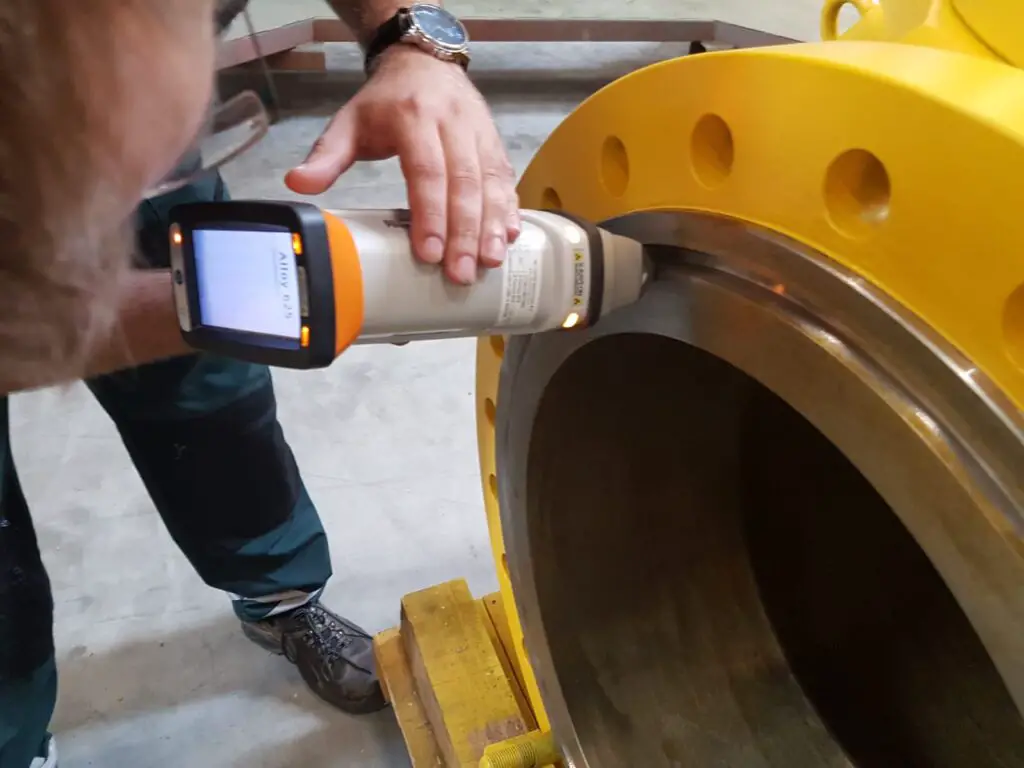
- PMI: Positive Material Identification.
- PWHT: Post Weld Heat Treatment.
- PN: Nominal Pressure (metric)
- PO#: Purchase order or number
- P-T: Pressure – Temperature
- PRV: Pressure Reducing Valve
- PSV: Pressure safety (relief) valve
- PFI: Pipe Fabrication Institute
- PFMA: Pipe Fittings Manufacturers Association
- PPI: Plastic Pipe Institute
- ppm: Parts per million
- P&ID: Piping and instrumentation diagram
- PLE: Plain large end
- PSE: Plain small end
- psi: Pounds per square inch
- psig: Pounds-force square inch, gauge
- PVC: Polyvinyl chloride
- PW: Potable water
- RF: Raised face (for flanges)
- RF Pad: Reinforcement PAD
- RFC: Released For Construction.
- RTJ: Ring type joint (flanges)
- RED: Reducer
- RAD: Radius/Radian
- RC: Rockwell hardness scale C
- RWMA: Resistance Welding Manufacturers’ Association
- RPM: Revolutions per minute
- Reqn: Requisition
- SAW: Submerged Arc Welding.
- SC: Sample Connection
- SCC: Stress Corrosion Cracking
- SCE: Safety Critical Equipment/Element
- SCH: Schedule.
- SDSS: Super Duplex Stainless Steel
- SIV: Service isolation valve
- SMAW: Shielded Metal Arc Welding
- SMLS: Seamless pipe or fitting
- SMYS: Specified Minimum Yield Strength
- SO: Slip on (Flange)
- Spec: Specification
- SR: Short Radius Elbow
- SRL: Single Random Length (Pipe Length)
- SS: Stainless Steel
- STD: Standard
- SW: Socket Weld
- SWE: Socket Weld End
- SWG: Swage
- SS. NO: Safety Shower & Eye Batch No
- TBE: Threaded Both Ends.
- TBE: Technical Bid Evaluation
- TYP: Typical
- TIG: Tungsten Inert Gas (Welding)
- ToFG: Time of Flight Diffraction (Ultrasonic Testing)
- TOS: Top Of Steel
- TSA: Thermally Sprayed Aluminum
- UNC: Unified Coarse Thread
- UNF: Unified Fine Threads
- UNS: Unified Numbering System
- VMA: Valve Manufacturers Association
- WCB: Wrought Carbon grade B
- WPQ: Welder Performance Qualification.
- WPS: Welding Procedure Specification
- WN: Weld Neck (Flange)
- WRC: Welding Research Council
- WT: Wall Thickness
- XS: Extra Strong
- XXS: Extra Extra Strong/Double Extra Strong