Recent Posts

Electrical Submersible Pumps: Working Principle, Components, Installation, Maintenance, Applications

An electric submersible pump (ESP) is an artificial lift pump that uses a motor to power a centrifugal pump through a series of stages to draw fluids and other materials out of a well. An ESP is a type of water pump that is designed to be immersed in a body of liquid and operates using an electric motor. The motor is connected to the pump and is sealed in a watertight casing, allowing the pump to be placed deep in wells, tanks, or reservoirs. ESPs are commonly used for pumping water or oil in oil wells, water wells, and other industrial or agricultural applications.

It is a multistage centrifugal pump that provides engineers with a flexible flow range and head. In addition, their high degree of energy economy makes them a good choice for various applications. An electrical submersible pump converts the liquid’s kinetic energy into work to increase pressure. These artificial lift pumps have recently gained popularity because of their widespread use on farms.

Historical Overview of Electrical Submersible Pump

In 1916, Russian inventor Armais Arutunoff was credited with developing the first electrical submersible pump. After moving to the United States in 1923, he established a company called the Russian Electrical Dynamo of Arutunoff (REDA). In the USA, he began seeking funders for his apparatus.

Initially, he presented his concept to Westinghouse, but it closed because the company’s engineers considered it impossible due to the principles of electronics. Later on, Arutunoff provided the solution to Phillips Petroleum’s problem in 1927 when the company was looking for a high-volume production method to make its high water-cut wells more profitable. 

In the late 20th century, the company was a subsidiary of Schlumberger and held the title of the world’s largest manufacturer of electrical submersible pumps. There was no connection between REDA Pump Company and any other business until 1969. It was acquired by Schlumberger in 1998 when that firm bought CAMCO.

Electrical Submersible Pump (ESP) System

A multistage centrifugal pump powers an ESP system’s series of centrifugal pumps to draw fluid to the surface of the well.   The ESP system is discussed as follows:

Turning on the ESP system

Even though the electrical submersible pump will run on a constant frequency supply, a soft starter or VSD can be used to get it going and clean out the well before the operation. It will allow the well to be cleaned up, production to begin at a low flow rate, and then ramped up as the well is rehabilitated.

Working Principle of ESP

A vertically oriented centrifugal pump in a borehole is the heart of an electrical submersible pump, which increases the speed of fluids with the help of impellers. The diffuser takes the fluid pumping energy created by the impellers and transforms it into pressure energy. 

In addition, the stages of an ESP System are typically configured with an impeller and diffuser. When liquid is pumped through the first stage’s impeller, its radial outward velocity is increased and centrifuged in the process. The fluid’s kinetic energy is turned into pressure as it reaches the diffuser from the impeller’s sharp edges.

Components of Electrical Submersible Pump

The components are typically comprised of tubing hung from the wellhead. The pump is attached to the tubing above the motor, and the motor is attached to the tubing below. Refer to Fig. 1 which shows the components of a typical electrical submersible pump system.

The following is a closer look at each component.

1.     Centrifugal Pump

The pump’s job is to provide the fluid with additional lift or transfer pressure to get the fluid to flow out of the wellbore at the required pace. It achieves this goal by first incorporating the fluid with kinetic energy by applying centrifugal force and then transforming that kinetic energy into potential energy by applying pressure. Pumps are manufactured in various diameters, so they may be used in the most common casing sizes.

2.     Electric Motor

An electric motor drives the electrical submersible pump. Several steps are required to generate adequate head pressure to raise the liquid to the surface. The motor size and horsepower determined the number of stages.

Moreover, motor size is the primary factor in determining ESP bottom-hole equipment’s total length and diameter. As the motor’s temperature rises during operation, the fluid is pulled into the pump to cool it.

Typical Electrical Submersible Pump System
Fig. 1: Typical Electrical Submersible Pump System

3.     Power Cable

ESP motors receive the necessary surface power through the ESP power cable. As it is not meant to bear any weight, it is usually banded or fastened to the production tubing running from the wellhead to the ESP unit. The three-phase electrical wire builds under the harsh conditions of a well.

Similarly, an electrical submersible pump has a strong power cable with an outer covering resistant to mechanical and electrical stress. Due to the harsh conditions in the well, the cable must be designed to be tiny in diameter, guarded against mechanical abuse, and resistant to physical and electrical damage.

4.     Controllers

The surface controller of an artificial lift pump is responsible for supplying power to the ESP motors and protecting the downhole ESP components from environmental hazards. Depending on the task, either variable-speed controllers or soft-start controllers are used.

  • A VSD, or variable speed drive, can be operated either mechanically or electronically in an electrical submersible pump.
  • The operating speed of a soft-start controller is fixed. Slowly but surely, it brings the pump motor up to its optimal operating speed and holds it there in a multistage centrifugal pump.

5.     Sensor

Installing a bottom-hole sensor that relays information in real-time about system parameters, including pump intake and output pressures, temperatures, and vibrations, can help operators maximize efficiency.

A sensor on the pump sends a real-time alarm to the operator if the reading is outside of the preset range, and the surface controller can make adjustments remotely or automatically.

ESP Installation

1.     Refueling the Engine

In the pump, set the motor in a vertical position on its base, double-checking and retightening any bolts as necessary. Ensure the engine is well hydrated by adding clean, cold water, rock the motor back and forth to remove any trapped air, and screw the plugs back in. Moreover, make sure there is no water leakage, and fix it.

2.     Waterproofing the Wires

The flat, three-core PVC-insulated cable connecting the submersible motor to the surface is three meters long. Therefore, make a watertight connection between the free end of the motor cable and the supply cable from the control panel in an artificial lift pump.

3.     Take a Look at the Valves

Ensure the well’s valves are closed while the electrical submersible pump is not in use to keep water from leaking back into the well.

4.     Testing the Motor’s Rotational Direction

Verify the submersible motor’s rotational direction after connecting the supply cable and motor cable watertight. According to the markings on the cable box, the proper rotational movement is anticlockwise. Now plug the motor into the control box and turn the switch on for a moment. To validate the sand guard’s rotational axis, clean water should pour over it. Then change the direction of rotation by switching any two lead wires in the control panel if the markings on the cable box are incorrect.

5.     Controlling for Rotational and Tactical Freedoms

In an electrical submersible pump, make sure the shaft of the pump and motor may freely spin and move up and down.

6.     Connecting the Pump to the Submerged Motor

After that, put together the tripod and the chain link and disconnect the submersible pump’s cable guard and filter. Maintain a vertical position of the artificial lift pump using the submersible motor and use a grub screw to attach the connection to the drive shaft or pump shaft. Screw the delivery pipe into the delivery casing after applying the threading compound. Raise the shaft once it’s assembled, and look for wiggle room.

Furthermore, install the connection onto the pump’s motor shaft, and lower the pump until it is flush with the inlet bracket. Finally, suspend the submersible pump from the chain block, and secure the supply hose with the clamp.

7.     Installing an Electrical System

In installing an electrical submersible pump, connect the submersible motor’s control panel to the engine with a single cable and then protect the underwater motor with grounding. Insist on a watertight connection at the cable’s end. Afterward, remove any excessive cable length and secure it to the engine’s starter terminals. When deciding on a wire size, keep low-voltage operating in mind.

8.     Lowering the Pump Securely

Lastly, connect a T-handle end of a poly rope to the pump’s lug and attach the end of the safety rope to the inner well cap on both ends. Make sure the outer well cover is securely fastened on the pump, and finish connecting the power wires.

Maintenance of Electrical Submersible Pump

There are certain guidelines on how to operate and maintain a facility and how to resolve any difficulties that may develop. After the ESP has been extracted from the well, its components can be disassembled and analyzed for information. It is true whether the structures are salvageable or have suffered a complete collapse. Some guidelines for maintaining a multistage centrifugal pump are discussed below:

a.     Check for Indications of Overheating

Check for indications of overheating the multistage centrifugal pump. If there is inadequate water in the well to cool the pump, or if the pump is faulty, the pump may overheat.

b.     Create Oil and Start the Motor

It is essential to regularly grease your pump to ensure its smooth operation.

c.      Examine the Engine

The pomp’s motor must also inspect often. Ensure that all connections of the artificial lift pump are tight and that the starter is not overheated.

d.     Replace the Hoses and Fix the Leaks

The seals and hoses of the electrical submersible pump are susceptible to wear and strain. If they are not periodically inspected, they can cause significant damage once they begin to fail.

Applications of Electrical Submersible Pump

The artificial lift pump is superior to other types because it may be used in various flow rates and depths and produce a significant artificial lift. A multistage centrifugal pump increases output by creating a more substantial bottom pressure than the natural production dynamic.

Moreover, these artificial lift pumps are used for various applications, including drainage, irrigation, water wells, slurry pumping, fire-fighting, sewage pumping, artificial lifts, seawater handling, oil wells, sewage treatment, deep well drilling, mine dewatering, offshore drilling rigs.

  • The artificial lift pump provides power for agricultural and industrial irrigation systems
  • Flooded areas are pumped out at construction sites
  • Sewage and sludge are common uses for these pumps. Pressure and level sensors are installed beneath the sewage levels to control the system.
  • A multistage centrifugal pump transports the crude oil to surface processing and storage tanks.
  • Oil is piped from deep underground wells to aboveground storage tanks
  • Submersible pump cables must be dependable and resistant to the elements if they are to be used in harsh environments. The power cables of the multistage centrifugal pump are suitable for use in both fresh and saline water.

Advantages of ESP

The benefits of an artificial lift pump are mentioned below:

  • Installed in straight sections, it can accommodate wells with a maximum inclination of horizontal
  • The multistage centrifugal pump allows for higher output despite inevitable water cuts due to pressure checks and secondary recovery
  • Being low-noise, low-risk, and low-impact means it can use in offshore and environmentally sensitive locations without causing too much disruption
  • Artificial lift pumps can withstand high GOR fluids, high temperatures, and corrosive acid gases found in good settings.
  • The electrical submersible pump has the capacity for large volumes, allowing for adaptation to changing fluid characteristics and flow rates over the well’s operational lifetime

Disadvantages of ESP

The disadvantages of multistage centrifugal pumps are mentioned below:

  • The well’s curvature limits its usability during deployment and landing.
  • Particles in production must keep to a minimum; fluids containing even trace amounts of sand and solids can significantly affect the system.
  • When a motor’s seals erode, water might seep inside and stop it from working until they’re fixed. The pump’s construction makes repairs tricky.
  • Equipment with moderate to high output rates necessitates casings with large outside diameters (more than 4.5 inches).
  • When calculating the tension and deflection of a part, manufacturers must take dogleg severity into account to guarantee correct assembly and functionality.

Conclusion

When selecting a pumping system, engineers and operators increasingly discover multistage centrifugal pump is the optimum option for downhole and surface applications. The electrical submersible pump industry is developing more durable pumps to make ESP systems more practical under conditions of high solids flow. To significantly extend the lifespan of artificial lift pumps, ongoing research focuses on enhancing the dependability of both individual components and integrated systems, as well as creating improved algorithms for operating surveillance and control.

Frequently Asked Questions (FAQs)

Q1: What are the primary reasons a multistage centrifugal pump stops functioning?

A: There are typically five leading causes for an artificial lift pump to stop working. Among these are issues associated with heat and overload, fluid pressure, motor seals, power surges, and stable voltage.

What is TEMA (Tubular Exchanger Manufacturers Association) and Why is it Important? TEMA Heat Exchangers

The Tubular Exchanger Manufacturers Association (TEMA) is a trade organization of manufacturers of heat exchangers, shell and tube type, in North America. Its mission is to promote the use of heat exchangers and to establish standards for the design and manufacture of heat exchangers. TEMA also provides educational and technical resources for its members, and it works to advance the understanding and acceptance of heat exchanger technology.

Founded in 1939, TEMA is synonymous with quality and integrity when it comes to shell and tube heat exchangers. TEMA Standards are accepted worldwide due to their authority on shell and tube heat exchanger mechanical design.

Importance of TEMA

TEMA is important because it sets industry standards for the design and manufacture of shell and tube heat exchangers, which are widely used in a variety of industrial processes to transfer heat between fluids. By establishing these standards, TEMA helps to ensure the safety and efficiency of heat exchanger equipment and promotes the use of best practices in the industry.

TEMA’s standards provide a common set of guidelines for designers, manufacturers, and users of heat exchangers, making it easier to compare and select equipment that is appropriate for a given application. The standards also help to ensure that heat exchangers are designed, manufactured, and tested consistently, which reduces the risk of equipment failure and improves performance.

In addition, TEMA provides educational and technical resources for its members, which helps to keep them informed about advances in heat exchanger technology and best practices for their use. Overall, TEMA plays an important role in promoting the use and understanding of heat exchanger technology, which contributes to the safe, efficient, and effective operation of many industrial processes.

TEMA Standards

TEMA standards are guidelines for the design and manufacture of shell and tube type heat exchangers, established by the Tubular Exchanger Manufacturers Association (TEMA). TEMA standards cover various aspects of heat exchanger design and construction, including:

Mechanical design: TEMA standards outline guidelines for the mechanical design of heat exchangers, including requirements for materials, welding, and fastening.

Heat transfer performance: TEMA standards specify performance requirements for heat transfer, including heat transfer rate and temperature control.

Hydraulic design: TEMA standards provide guidelines for the hydraulic design of heat exchangers, including requirements for pressure drop, flow rate, and turbulence.

Testing: TEMA standards outline procedures for testing heat exchangers, including requirements for pressure testing, leak testing, and performance testing.

Assembly and maintenance: TEMA standards provide guidelines for the assembly and maintenance of heat exchangers, including requirements for cleaning, inspection, and repair.

TEMA standards are widely recognized and respected in the industry, and they are used by heat exchanger manufacturers, designers, and users to ensure that heat exchanger equipment is designed, manufactured, and tested to a high level of quality. Adherence to TEMA standards helps to minimize the risk of equipment failure, improve performance, and promote the safe and efficient use of heat exchanger technology.

TEMA Latest edition

The latest edition of the TEMA standards is TEMA 10th Edition, which was published in 2019. TEMA releases new editions of its standards periodically to incorporate the latest developments in heat exchanger technology and to address any changes in industry practices. The 10th edition of the TEMA standards includes updates to the guidelines for mechanical design, heat transfer performance, hydraulic design, testing, and assembly and maintenance. It is important for heat exchanger manufacturers, designers, and users to be familiar with the latest edition of the TEMA standards to ensure that their equipment is up-to-date and meets the latest industry standards for quality and performance.

Broadly the 10th TEMA Edition covers the following contents:

  • Heat exchanger Nomenclature
  • Heat exchanger Fabrication Tolerances
  • General Fabrication and Performance Information
  • Information related to Heat exchanger Installation, Operation, and Maintenance.
  • Mechanical Standards TEMA class RCB Heat Exchangers
  • Flow Induced Vibration
  • Thermal Relations
  • Physical properties of Fluids
  • Recommended Good Practices
  • Appendix A explaining tube sheets

TEMA Heat Exchangers

TEMA heat exchangers are shell and tube type heat exchangers that are designed and manufactured in accordance with the standards set by the Tubular Exchanger Manufacturers Association (TEMA). TEMA heat exchangers are used to transfer heat between two fluids, where one fluid flows through the tubes and the other fluid flows over the outside of the tubes in the shell.

TEMA heat exchangers are widely used in a variety of industrial processes, including power generation, chemical processing, oil refining, and HVAC systems. They are designed to meet specific performance requirements, such as heat transfer rate, pressure drop, and temperature control, and they can be customized to meet the unique requirements of different applications.

TEMA heat exchangers are known for their reliability and efficiency, and they are widely recognized as a cost-effective and flexible solution for heat transfer applications. By adhering to TEMA’s standards, manufacturers of TEMA heat exchangers ensure that their equipment is designed, manufactured, and tested to a high level of quality, which helps to minimize the risk of equipment failure and improve performance.

Advantages of TEMA Heat Exchangers

There are several advantages to using TEMA heat exchangers, including:

Reliability: TEMA heat exchangers are designed and manufactured in accordance with strict industry standards, which helps to ensure that they are reliable and safe for use in a wide range of industrial processes.

Efficiency: TEMA heat exchangers are designed to transfer heat effectively, which can help to increase energy efficiency and reduce costs.

Customizability: TEMA heat exchangers can be customized to meet the unique requirements of different applications, making them a flexible solution for a wide range of heat transfer needs.

Cost-effectiveness: TEMA heat exchangers are widely recognized as a cost-effective solution for heat transfer applications, and they offer a good balance of performance and cost.

Industry recognition: TEMA heat exchangers are widely recognized and respected in the industry, which helps to ensure that they are a well-regarded and reliable solution for heat transfer needs.

Overall, TEMA heat exchangers offer a combination of reliability, efficiency, and cost-effectiveness that makes them a popular choice for many industrial heat transfer applications.

TEMA vs ASME: Difference between TEMA and ASME

TEMA (Tubular Exchanger Manufacturers Association) and ASME (American Society of Mechanical Engineers) are both organizations that establish standards for the design and manufacture of heat exchangers, but they have some differences:

Scope: TEMA standards focus specifically on the shell and tube-type heat exchangers, while ASME standards cover a wider range of pressure vessels and boilers, including shell and tube heat exchangers.

Emphasis: TEMA standards place a greater emphasis on the mechanical design of heat exchangers, including requirements for materials, welding, and fastening. ASME standards place more emphasis on the pressure-containing aspects of heat exchangers and also cover performance requirements for heat transfer and hydraulic design.

Compliance: TEMA standards are primarily used in North America, while ASME standards are used globally. Some heat exchanger manufacturers may comply with both TEMA and ASME standards to ensure that their equipment meets the requirements of a wide range of customers.

Technical resources: TEMA provides educational and technical resources for its members, including training and technical support, while ASME provides a wide range of resources and services, including code development, certification, and accreditation programs.

Both TEMA and ASME play important roles in establishing standards for the design and manufacture of heat exchangers, and they help to ensure that heat exchanger equipment is designed, manufactured, and tested to a high level of quality. Ultimately, the choice of which standards to comply with will depend on the specific requirements of the heat exchanger and the preferences of the manufacturer, designer, or user.

What is a Mechanical Datasheet? Process Datasheet vs Mechanical Datasheet

A mechanical datasheet is a document that provides technical specifications and information about the mechanical aspects of a product or device. It typically includes information on dimensions, weight, materials, tolerance, temperature range, operating conditions, mechanical strength, and durability, among other things. The purpose of a mechanical datasheet is to provide engineers, designers, and manufacturers with the information they need to properly design, manufacture, and use the product.

A Mechanical Datasheet or MDS in short form is a basis for equipment procurement and fabrication by a vendor or manufacturer. The main responsibility for developing a mechanical datasheet lies with the mechanical engineer of that project. The main basis (input) of mechanical datasheet generation is a process datasheet from the process engineer. The involved Mechanical Engineer uses the process datasheet and further adds mechanical details like the equipment size and associated detail information for each equipment item, and provides a detailed sized equipment list for other engineering disciplines to complete their detailed engineering and design.

The Mechanical Datasheet (MDS) is the first step in the designing and procurement process of any equipment. The MDS is always accompanied by a Specification with a detailed description of the equipment, technological role, environmental characteristics, etc.

Items Requiring Mechanical datasheet

A mechanical datasheet can be generated for a variety of mechanical equipment, including:

  • All static and rotating mechanical pieces of equipment in the project like pumps, tanks, compressors, pressure vessels, reactors, turbines, exchangers, etc.
  • Mechanical components, such as gears, bearings, shafts, and springs
  • Mechanical assemblies, such as engines, transmissions, and pumps
  • Mechanical systems, such as HVAC systems and piping systems
  • Mechanical devices, such as valves, actuators, and fasteners
  • Consumer products, such as appliances, tools, and toys
  • Industrial equipment, such as cranes, hoists, and conveyors
  • Aerospace and defense equipment, such as aircraft, missiles, and military vehicles
  • Medical equipment, such as prosthetics, implants, and surgical instruments.

In general, any type of mechanical equipment that requires precise specifications and information can benefit from a mechanical datasheet.

Equipment Datasheet in Oil and Gas

An equipment datasheet is a mechanical datasheet for any equipment. In the oil and gas industry, an equipment datasheet is a document that provides technical specifications and information about a specific piece of equipment used in the production, processing, or transportation of oil and gas. It typically includes information on the equipment’s dimensions, weight, materials, temperature range, pressure range, operating conditions, and any other relevant specifications that are critical for its safe and efficient operation. The purpose of an equipment datasheet is to provide detailed information to engineers, operators, and maintenance personnel, enabling them to properly design, install, and maintain the equipment. Equipment datasheets are commonly used for a wide range of oil and gas equipment, including pumps, valves, compressors, heat exchangers, pipelines, and storage tanks.

Advantages of Mechanical Datasheets

A mechanical datasheet provides several advantages, including:

  • Improved design: A mechanical datasheet provides critical specifications that engineers need to design components and systems that will be compatible with the equipment.
  • Enhanced manufacturing: The detailed information in a mechanical datasheet can help manufacturers produce the equipment to the required specifications, reducing the risk of errors and defects.
  • Better performance: By specifying operating conditions, temperature range, and other critical parameters, a mechanical datasheet can help ensure the equipment operates efficiently and safely.
  • Reduced risk: By providing accurate specifications, a mechanical datasheet reduces the risk of equipment failure and ensures that the equipment is used in a safe and appropriate manner.
  • Efficient maintenance: The information in a mechanical datasheet can help maintenance personnel diagnose and fix problems more efficiently, reducing downtime and maintenance costs.
  • Improved documentation: A mechanical datasheet provides a comprehensive and easily accessible source of information that can be used for reference, troubleshooting, and regulatory compliance.

Overall, the use of a mechanical datasheet can lead to improved quality, safety, and efficiency in the design, manufacture, and operation of mechanical equipment.

Examples of Mechanical Datasheets

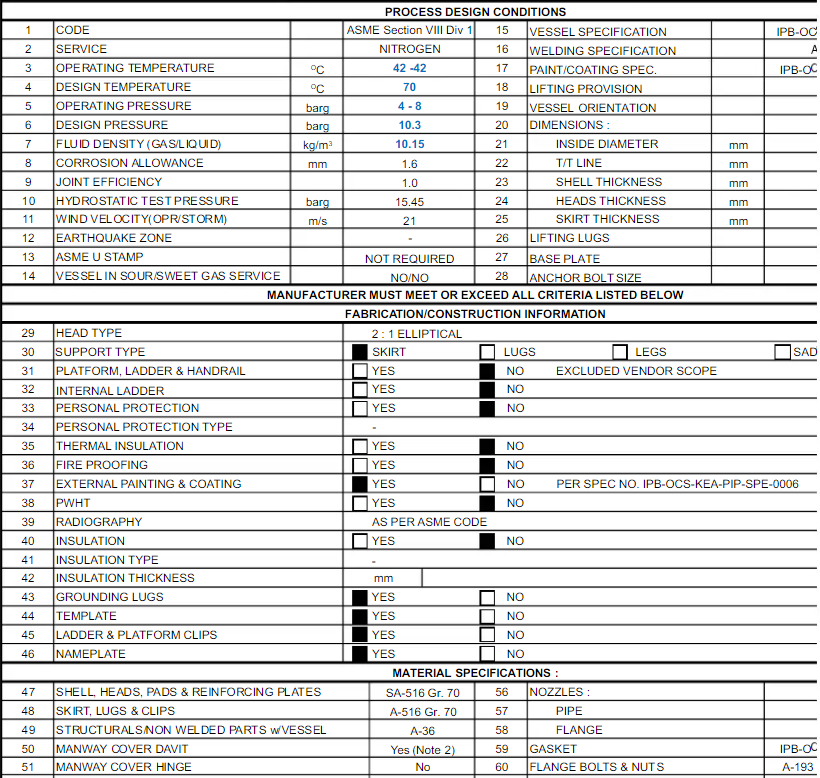
The image in Fig 1 shows parts of a typical example mechanical datasheet for a nitrogen receiver. In a similar way, mechanical datasheets of each piece of equipment and mechanical items may be generated by the mechanical engineer.

Example of a Typical Mechanical Datasheet
Fig. 1: Example of a Typical Mechanical Datasheet

Process Datasheet vs Mechanical Datasheet: Difference between a Process Datasheet and Mechanical Datasheet

A mechanical datasheet and a process datasheet are both documents used to provide technical information about equipment, but they have different focuses and purposes.

A mechanical datasheet provides technical specifications and information about the mechanical aspects of a product or device, such as its dimensions, weight, materials, tolerance, temperature range, operating conditions, and mechanical strength. Its focus is on the physical characteristics and capabilities of the equipment.

A process datasheet, on the other hand, provides information about the process or application in which the equipment will be used. It typically includes information on process conditions, fluid properties, flow rates, temperatures, pressures, and chemical composition, as well as performance requirements and safety considerations. Its focus is on how the equipment will be used in a specific process and what conditions it will need to operate under.

The process datasheet of any specific equipment is the input for generating the mechanical datasheet for that specific equipment.

In summary, a mechanical datasheet provides information about the equipment itself, while a process datasheet provides information about how the equipment will be used in a specific process. Both documents are important for ensuring that the equipment is used safely, efficiently, and effectively.

Roles of Pipeline Engineers: Piping Engineer vs Pipeline Engineer

In the oil and gas industry, Pipeline engineers play a very important role. Pipeline Engineers design, route, plan, and helps in the construction and maintenance of onshore and offshore pipelines. As we all know that transporting crude oil, natural gas, refined products, and water through pipelines is the cheapest industrial option available to engineers. So, quality pipeline engineers are always in demand. In this article, we will understand the requirements and roles, and responsibilities of a pipeline engineer.

What is Pipeline Engineering?

Pipeline Engineering is a branch of engineering technology that deals with fluid transportation through pipelines. It is a sub-part of mechanical engineering that deals with the design, construction, maintenance, and operation of pipelines. Pipelines are extensively used to transport fluid, gas, or solid materials from one location to another. Pipeline engineering consists of the study of pipeline transportation systems, hydraulic and thermal analysis, pipeline integrity management, and the development of pipeline materials, coatings, and corrosion control methods. Pipeline engineers work to ensure the safe and efficient operation of pipelines and are involved in the entire lifecycle of a pipeline, from its initial conception to decommissioning.

What is a Pipeline Engineer?

A pipeline engineer is a professional who designs, develops, and manages the construction of pipelines used to transport oil, natural gas, water, and other substances. They are responsible for ensuring the safe and efficient movement of these materials from one location to another. This includes tasks such as route selection, material selection, and construction supervision, as well as ongoing maintenance and repair.

Types of Pipeline Engineers

Pipelineline engineers work in various roles in industries. Depending on the specific type of job they perform, pipeline engineers can be grouped into the following classes.

  • Pipeline Design Engineers: Their main responsibility is creating plans and designs for pipelines, taking into consideration factors such as safety, cost-effectiveness, and environmental impact.
  • Construction Pipeline Engineers: They oversee the construction process, ensuring that the pipeline is built according to design specifications and industry standards.
  • Maintenance Pipeline Engineers: They are responsible for the ongoing inspection, repair, and maintenance of pipelines to ensure their safe and efficient operation.
  • Pipeline Integrity Engineers: This type of pipeline engineer ensure that pipelines meet integrity and safety standards, including performing risk assessments and developing plans to address potential threats to the pipeline.
  • Project Pipeline Engineers: They manage pipeline projects from start to finish, overseeing design, construction, and commissioning.
  • Pipeline Operations Engineers: They manage the day-to-day operations of pipelines, including monitoring flow rates and pressure, and ensuring that pipelines are operating efficiently.

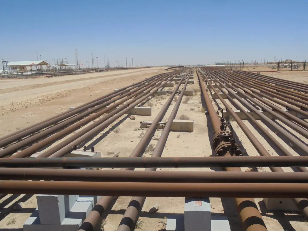
So, obviously, the roles and responsibilities of each type of pipeline engineer will vary depending on the specific type they fall into. Fig. 1 below shows some typical aboveground pipelines.

Examples of Typical Aboveground Pipelines
Fig. 1: Examples of Typical Pipelines

Roles and Responsibilities of Pipeline Engineers

The roles and responsibilities of pipeline engineers can vary depending on the type of pipeline engineer and the specific project they are working on, but some of the most common responsibilities are:

  • Designing new pipelines
  • Developing pipeline routes, considering the environmental and geological issues into account
  • Overseeing construction
  • Inspection of Testing of installations and performing quality control
  • Integrity and corrosion control on existing pipeline systems
  • Maintenance to fix faulty pipelines and take repair actions.
  • Meeting with clients/operations team to define pipeline requirements.
  • Preparing pipeline specifications.
  • Conducting site surveys and research.
  • Estimating manhours, materials, time, and budget.
  • Preparing pipeline maps, blueprints, and mechanical diagrams.
  • Helping in the construction and installation process of pipeline infrastructure and systems.
  • Managing the pipeline project workflow.
  • Monitoring the day-to-day operations of pipelines, including flow rates, and pressure, and ensuring that pipelines are operating efficiently.
  • Ensuring that pipelines meet safety and regulatory standards, and developing plans to address potential threats to the pipeline.
  • Working with other engineers, geologists, environmental scientists, and contractors to complete pipeline projects.

How to Become a Pipeline Engineer?

To become a pipeline engineer, you typically need to follow these steps:

  • Earn a bachelor’s degree: Most pipeline engineering positions require a bachelor’s degree in engineering, with a focus on mechanical, civil, or petroleum engineering being the most common.
  • Gain experience: Entry-level positions in pipeline engineering often require 2-5 years of experience in a related field, such as construction or oil and gas operations. You can gain experience through internships, co-op programs, or working as a junior engineer.
  • Obtain professional certification: While not mandatory, obtaining a professional engineering (PE) license can increase your employment opportunities and earning potential. To obtain a PE license, you must pass the Fundamentals of Engineering (FE) exam and have several years of engineering experience.
  • Stay informed of industry trends: Pipeline engineering is a rapidly evolving field, so it’s important to stay up-to-date with the latest developments and technologies. This can be done through attending conferences, reading industry publications, and participating in professional organizations.
  • Develop strong communication skills: Pipeline engineers often work with teams of professionals from different backgrounds and disciplines, so strong communication and interpersonal skills are essential.
  • Build a network: Building relationships with other professionals in the industry can help you stay informed of job opportunities and developments in the field. Joining professional organizations and attending industry events can help you build your network.

Pipeline Engineers Jobs

A vast majority of pipeline engineers get jobs in the oil and gas industry. However, there are various other industries where pipeline engineers get jobs. Some of the commons industries that employ pipeline engineers are:

  • Oil and gas: Pipeline engineers play a crucial role in the oil and gas industry, designing and maintaining pipelines that transport oil and natural gas from production sites to refining and distribution centers.
  • Water and wastewater: Pipeline engineers are also employed in the water and wastewater treatment industry, designing and maintaining pipelines that transport water and wastewater to and from treatment plants.
  • Chemical: Pipeline engineers work in the chemical industry, designing and maintaining pipelines that transport chemicals and other hazardous materials from production sites to storage and distribution centers.
  • Mining: In the mining industry, pipeline engineers design and maintain pipelines that transport minerals and other raw materials from mines to processing facilities.
  • Manufacturing: Pipeline engineers also work in the manufacturing industry, designing and maintaining pipelines that transport raw materials, semi-finished products, and finished goods between production facilities.
  • Energy: In the energy industry, pipeline engineers work on projects related to the transmission and distribution of electricity and other forms of energy, such as wind and solar power.
  • Government agencies: Pipeline engineers are also employed by government agencies, such as the U.S. Department of Energy or the Environmental Protection Agency, to oversee the design, construction, and maintenance of pipelines and other energy infrastructure projects.

Salary of Pipeline Engineers

The salary of a pipeline engineer depends on various factors like

  • Work Experience
  • Educational experience
  • Type of Work
  • Knowledge and Capability
  • Type of company
  • Work location.

On average, pipeline engineers in the United States earn an annual salary of around $92,000, according to Glassdoor. However, experienced pipeline engineers can earn significantly more, with some earning upwards of $150,000 per year. The highest-paying industries for pipeline engineers are typically oil and gas, manufacturing, and energy. Additionally, obtaining a professional engineering (PE) license can increase earning potential of pipeline engineers.

In India, entry-level pipeline engineers get an average salary of 5 to 15 lakh INR whereas experienced (12+ years) pipeline engineers get an average salary of 20-30 lakh INR.

Pipeline Engineers vs Piping Engineers

Many a time, the term piping engineers and pipeline engineers are used interchangeably as some of the skillsets of a piping engineer and a pipeline engineer is similar in nature. However, there are some specific differences between a piping engineer and a pipeline engineer. To understand the differences between a piping engineer and a pipeline line I suggest you first know the differences between piping and a pipeline.

The most common difference between a piping engineer and a pipeline engineer is their work scope.

Both piping engineers and pipeline engineers may work on similar projects, but the focus of their work (work scope) is different. Piping engineers may have a more specialized focus, working on the design of pipelines within a single facility, while pipeline engineers have a broader focus, working on the design of pipelines that span long distances. Piping systems are usually designed based on ASME B31.1/B31.3 codes whereas pipeline systems are designed based on ASME B31.4/B31.8 codes.

Which Career Option is better: Piping or Pipeline?

Neither career option is inherently better, as both piping and pipeline engineering offers unique challenges and opportunities. The best career option for an individual will depend on their personal interests, skills, and goals.

For those who enjoy hands-on design and construction work, and have a strong technical background, a career as a piping engineer may be a good fit. Piping engineers typically work on smaller projects and have more direct involvement in the design and construction of pipelines within a single facility.

For those who enjoy working on complex, large-scale projects and have a strong background in risk assessment and project management, a career as a pipeline engineer may be a good fit. Pipeline engineers are responsible for designing and constructing pipelines that span long distances, often crossing multiple state or national borders, and must consider a wide range of factors, including environmental impact, regulations, and community engagement.

Ultimately, both careers offer the opportunity to make a positive impact in the energy and manufacturing industries, and both offer competitive salaries and opportunities for career growth.

Pipeline Engineering Courses

Various organizations provide courses for pipeline engineers to enhance the skills required for pipeline engineering. Some of the popular pipeline engineering courses can be found as mentioned below:

  • Certificate course in pipeline engineering by Lloyd Maritime Academy
  • Pipeline Engineering course by PetroSkills
  • Professional Certificate of Competency in Onshore & Offshore Pipeline Systems by Engineering Institute of Technology (EIT)
  • Pipeline Engineering Course by the University of Calgary
  • Pipeline Engineering Courses at UBC (the University of British Columbia)

Online Video Courses related to Pipeline Engineering

If you wish to explore more about pipeline engineering, you can opt for the following video courses

Pipe End Cap Fittings or Piping Caps: Pipe Caps vs Plugs: Pipe End Caps vs Blind Flanges

Pipe caps are a type of pipe fitting to cover the pipe end. In the Piping, Plumbing, and Pipeline industry, pipe end caps are widely used to block the ends of pipes. They work in a similar fashion to pipe plugs or blind flanges. Even though this is a very important pipe fitting, most of the time the significance of pipe caps is overlooked. In this article, we will explain some details about pipe cap fittings; their types, materials, standards, specifications, and differences with plugs and blind flanges.

What is a Pipe Cap?

A pipe end cap is a pipe fitting that held the pipe content within itself by blocking the end parts. It acts as a protective device for the plumbing, piping, and pipeline system by not allowing outside matters to enter the inside of the pipe. Due to this pipe caps are also known as pipe end protectors. Industrial pipe caps are widely used in domestic, commercial, and industrial water supply lines, Steam pipes in power plants, and various oil, gas, and chemical lines in process and chemical industries.

Pipe Cap Materials

A range of materials is used to manufacture piping end caps. Depending on the pipe material and service, pipe cap materials are selected. Some of the common industrial pipe cap materials are:

  • Carbon Steel (ASTM A234 WPB)
  • Low-Temperature Carbon Steel (ASTM A420)
  • Alloy Steel (ASME A234 WP1 / WP5 / WP9 / WP11 / WP22 / WP91)
  • Aluminum
  • Nickel Alloy (ASTM B336, Monel 400, Inconel 825, Inconel 625, Hastelloy C 276, Cupro Nickel)
  • Nylon or polyamide
  • Stainless Steel (ASTM A182, ASTM A403)
  • Duplex Stainless Steel (ASME S815 UNS No S31803, S32205)
  • Polyethylene
  • Polypropylene
  • Vinyl
  • FRP
  • Silicone rubber etc.

Shapes of Pipe Caps

Pipe caps are manufactured in various shapes to cater to various application demands. Some of the common pipe cap shapes are:

  • Round
  • Square
  • Rectangular
  • “I” Shape Cap
  • Oval
  • Hemispherical
  • “U” Shape Cap
  • Hex Cap etc.

Pipe Cap Standards

ASME B16.9 provides pipe dimensions, ratings, testing, tolerances, and marking requirements for Steel Piping cap fittings. Usual pipe end caps are manufactured from NPS 1/2 inches through 48 inches with pipe schedules 10, 20, 30, STD, 40, 60, 80, XS, XXS, 100, 120, 140, and 160 as applicable. Other pipe end caps standards are:

  • ASME B16.11
  • DIN 2617
  • DIN 28011
  • MSS SP 43
  • EN 10253

Types of Pipe Caps

Pipe caps are classified based on their applications, material of construction, construction features, etc.

Depending on the construction features, the following pipe cap types are found:

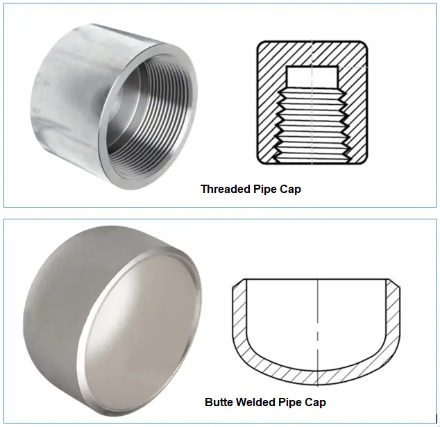
  • Threaded Caps: Threaded pipe caps have female threads to fit the pipe end with the caps. The thread can be straight or tapered.
  • Welded Caps: Welded pipe caps can be either butt welded or socket welded caps.
  • Tapered Caps: These types of pipe caps have tapered sides that help in a close fit. Tapered caps can be used as a multi-functional pipe fitting and can be used with male and female NPT threads, male straight threads, and straight tubes and bars.
  • Anti-roll Caps: These pipe cap types are round in shape but with a square end to prevent pipes and tubes from rolling.
Threaded and Welded Pipe Caps
Fig. 1: Threaded and Welded Pipe Caps

Depending on pipe cap materials, they can be classified as:

  • Metallic Pipe Caps: Made from metals like Steel, Aluminum, etc. and
  • Non-metallic Pipe Caps: Made from non-metals like plastics.

Specification of Pipe Caps

Pipe end caps are specified by various parameters as listed below:

  • Pressure Temperature Rating
  • Pipe Cap Material: Metallic/non-metallic
  • Diameter: Diameter of the connection pipe
  • Type: Exact type of pipe cap required.
  • Shape: Shape of pipe caps (Round/Square/Rectangular)
    • Head type of Round Pipe caps: (flange or slotted head, knurled or faceted head, retaining head, and tear tab)
    • Length and Width for Rectangular pipe caps.
  • Thread type and size: NPT/BSP/Metric
  • Design Standard: ASME/DIN
  • Coating/Polishing/Galvanizing Requirements

Pipe Caps vs Plugs

Plugs are piping also serve a similar function that a pipe cap serves. But there is a major difference between the pipe cap and the pipe plug. Pipe caps usually have female thread whereas pipe plugs have male threads. It means a pipe is inserted into the threads of a pipe cap whereas the plug is inserted into the pipe. Other differences between the two are:

  • Purpose: A pipe cap is used to close off the end of a pipe permanently to make it a dead end, whereas a pipe plug is generally used to temporarily seal the pipe end for maintenance or testing.
  • Installation: Pipe caps are can be welded or threaded while pipe plugs are generally threaded.
  • Pressure rating: Pipe caps are designed to handle the system pressure but pipe plugs usually do not handle system pressure.

Pipe Caps vs Blind Flanges

A blind flange is a type of piping flange that serves a similar function as a pipe cap. However, there are some distinct differences between a pipe cap and a blind flange. These are listed below:

  • Purpose: A pipe cap closes the end of a pipe permanently, but a blind flange is used to isolate a section of a pipeline or seal off a pressurized system.
  • Production: Blind flanges are forged or cast components whereas pipe caps are generally made by forming.
  • Installation: Pipe caps are installed by welding or screwing whereas blind flanges are generally installed by bolting and a gasket is inserted in between.
  • Seal: Pipe caps provide permanent sealing whereas blind flanges are used to provide a pressure-retaining barrier with a mating flange. Blind flanges are used to connect or disconnect parts of piping or valves.
  • Face type: Pipe caps have a flat or convex end face, while blind flanges have a raised face.
  • Pressure testing: Blind flanges can be used for pressure testing, while pipe caps cannot.
  • Maintenance: Being bolted, blind flanges can be easily removed for maintenance or repair, while pipe caps are permanent and cannot be easily removed.
  • Cost: Blind flanges are typically more expensive than pipe caps due to their higher level of functionality.

Online Video Course on Piping and Pipe Fittings

To enrich yourself with piping and pipe fitting details you can opt for the following online video courses

What is a Pipe Union? Its Materials, Parts, Applications, Types, and Differences with Pipe Couplings

A pipe union is a type of pipe fitting that creates a secure and semi-permanent connection between two pipes. The pipes can easily be separated without causing any piping deformation. Pipe union connections are mostly used for small bore pipe connections. Whenever an easy assembly and disassembly along with a positive sealing is required, pipe union fittings are used. Common pipe unions are usually manufactured in a size range from 1/8 inches to 4 inches.

Parts of a Pipe Union Fitting

A pipe union has three parts; a male end, a female end, and a nut (Refer to Fig. below). The male and female ends of the piping union are sealed together in the nut to act as a single pipe union assembly. The female end has threads on the inside surface whereas the male end has threads on the outside surface. The nut provides the required sealing pressure to the union joint.

The threaded pipe union is threaded to be NPT per ASME B1.20.1 whereas the nut is straight thread as per ASME B1.1. The seating surfaces of the joint shall be integral metal-to-metal, ball-to-cone design.

Applications of Pipe Unions

As pipe unions have a high probability of leakage, their use is generally limited to non-hazardous and non-flammable services. The use of pipe unions is found in the following systems:

  • Fire Protection Piping System
  • Water and Wastewater piping systems
  • Non-critical Process piping systems with low pressure and temperatures
  • Plumbing Applications.
Pipe Unions
Pipe Unions

Types of Pipe Unions

There are two types of pipe unions that are found in applications as listed below:

Ground Joint Union: It comprises an angle that is cut into the piping union to make the two sections meet to increase the joint surface area which helps in proper seating. It consists of three pieces.

Flange Union: In this type of union, a pair of flanges hold two pipes together by screwing them on the ends of the pipes. This is usually used in plumbing services to hold both pipes together. It consists of only two pieces.

Again, depending on the joint connection, there are two types of pipe unions; threaded union and socket welded union.

Materials for Pipe Unions

Industrial pipe unions are made from various materials. Some of the common pipe union materials are:

  • Carbon Steel (ASTM A105, A350, A234)
  • Stainless Steel (ASTM A182 , A312, A403)
  • Cast Iron
  • Copper (ASTM SB111)
  • Brass
  • Nickel (ASTM B336)
  • Alloy Steel (A335/A691)
  • Duplex Stainless Steel (A790)
  • Aluminum
  • Bronze
  • Plastics like PE, PVC,
  • Rubber, etc

Metallic pipe unions are preferred for piping industries whereas plastic pipe unions are generally used in plumbing services.

Pipe Union Manufacturing Standards

The most widely used pipe union standards are:

  • MSS SP 83, and
  • ASME B16.11
  • BS 3799

Features of Pipe Union

The main characteristic features of pipe unions are:

  • Two pipes of different sizes can be joined together using a pipe union.
  • The joining can be easily disengaged.
  • Metering and regulating devices are connected using unions.
  • They are easy to install and economical.

Specification of a Pipe Union

A pipe union fitting is generally specified by the following information:

  • Manufacturing standard
  • Material Grade
  • Dimension/Pressure Class: Class 2000/3000/6000/9000
  • Type of Union: Socket union/Threaded union
  • Size
  • Value-added services: galvanizing/coating/polishing requirements

Difference between Pipe Coupling and Pipe Union | Pipe Union vs Pipe Coupling

Pipe unions are quite similar to pipe couplings. However, they have some differences as mentioned below:

1. Pipe Connection:

Two coupled pipes screw together directly, one inside the other. While taking the pipes apart, every pipe that connects to the coupled pipe needs to turn.

While in a pipe union, the two pipe ends don’t screw into one another—they each screw into a third piece. When one pipe needs to come apart from the other, the union piece simply screws onto one of the two pipes completely. If both ends of a pipe are attached using a union, the pipe may be removed on its own without unscrewing the other pipes in the system.

2. Joining Method:

Pipe couplings are available in three pipe joining modes; threaded, butt welded, and socket welded. On the other hand, pipe unions only have two pipe joining modes; threaded and socket welded.

3. Use:

Pipe couplings can be used in comparatively high-pressure services as compared to pipe union connections. Couplings are used in pipe racks whereas unions are used for steam trap assemblies and control valve manifolds. Couplings are used as a piping/pipeline extension while unions are more versatile as they are used with other pipe components as well.

4. Cost:

The cost of pipe unions is comparatively higher than the cost of pipe couplings.

5. Purpose:

Pipe couplings are generally used as a permanent joint, whereas pipe unions are specifically used for parts requiring maintenance and repair for easy disengagement.

Possible Causes of leakage from pipe union

The following are some of the probable causes that can create a leakage problem from pipe unions.

  • Improper or low assembly torque of the collar
  • Imperfections of the metal-to-metal seat
  • Dirt on the metal-to-metal seat
  • High friction in the collar threads
  • Piping misalignment causing improper seating or uneven tightening
  • High vibration during operation
  • In addition to the possible cause of leakage through pipe thread or socket weld failure.

In certain applications, a pipe union as a pipe fitting is used as a protective system to avoid galvanic corrosion. Plastic pipe unions when used with two pipes made of different metals, act as a barrier for electronic movement from one pipe metal to the other. The physical separation slows down the galvanic corrosion process.

Online Video Course on Piping and Pipe Fittings

To enrich yourself with piping and pipe fitting details you can opt for the following online video courses