A clevis hanger is a type of mechanical support device widely used in the piping and plumbing industries. This pipe attachment is specifically designed to support and suspend piping systems, such as pipes, tubes, and conduits, from overhead structures or beams. Clevis hanger provides vertical adjustments and is quite flexible for supporting pipes. They are in general preferred for non-insulated piping systems. However, clevis hangers can be used for insulated piping systems, as well.
Components of a Clevis Hanger
The clevis hanger consists of two main components: a U-shaped clevis and a threaded rod. The clevis is a metal bracket or yoke with two holes that are used to attach the hanger to the supporting structure. One hole is for connecting the hanger to the threaded rod, while the other hole is used to fasten the hanger to the structure using bolts or other suitable means.
The threaded rod, often referred to as a hanger rod or hanger bolt, extends vertically downwards from the clevis. It provides the means to adjust the height of the suspended piping system by turning the rod clockwise or counterclockwise.
Applications of Clevis Hangers
Clevis hangers are commonly used in applications where there is a need to support pipes, ducts, or conduits while allowing for some degree of movement or adjustment. They are often used in HVAC (Heating, Ventilation, and Air Conditioning) systems, plumbing installations, fire sprinkler systems, and industrial piping systems. Clevis hangers are commonly used for the following systems:
HVAC (Heating, Ventilation, and Air Conditioning): Clevis hangers are extensively used in HVAC systems to support ductwork, air handling units, and ventilation pipes.
Plumbing Systems: Clevis hangers provide support for pipes and conduits in plumbing installations, including water supply lines, drainage systems, and sewage pipes.
Fire Sprinkler Systems: Clevis hangers are used to suspend fire sprinkler pipes and ensure proper alignment and support for the sprinkler system.
Industrial Piping: Clevis hangers are employed in industrial settings to support various types of pipes, including process piping, chemical lines, steam lines, and hydraulic systems.
Commercial Buildings: Clevis hangers are utilized in commercial structures such as office buildings, hospitals, schools, and shopping centers to support plumbing and HVAC systems.
Power Plants: Clevis hangers are used in power generation facilities to support piping systems for steam, water, fuel, and other fluids.
Oil and Gas Industry: Clevis hangers find applications in the oil and gas sector for supporting pipelines, including offshore platforms, refineries, and pipelines.
Petrochemical Plants: Clevis hangers are used in petrochemical facilities to support various piping systems involved in the transportation and processing of chemicals.
Water Treatment Plants: Clevis hangers provide support for pipes used in water treatment facilities, including filtration systems, pump stations, and distribution networks.
Industrial Process Systems: Clevis hangers are employed in a wide range of industrial processes, including food processing, pharmaceutical manufacturing, chemical production, and pulp and paper mills.
The design of clevis hangers allows for easy installation and adjustment, making them versatile and convenient for various pipe support requirements. They provide stability and help distribute the weight of the suspended pipes or conduits evenly, reducing stress and potential damage to the piping system and the supporting structure.
Materials for Clevis Hangers
Clevis hangers are typically made from various durable and corrosion-resistant materials to ensure their strength and longevity. The choice of material depends on the specific application and environmental factors. Here are some common materials used in the design of clevis hangers:
Carbon Steel: Carbon Steel is a popular choice due to its high strength and durability. However, carbon steel is prone to corrosion and hence suitable measures must be exercised to reduce corrosion.
Stainless Steel: Stainless steel provides high corrosion resistance along with the required strength. But, stainless steel is costly as compared to carbon steel.
Galvanized Carbon Steel: Galvanized carbon steel is a good choice which helps in protecting corrosion as well.
Cast Iron: Cast iron clevis hangers are known for their exceptional strength and load-bearing capacity. They are often used in heavy-duty applications.
Malleable Iron: Malleable iron combines the strength of cast iron with improved malleability and ductility, making it easier to shape and manipulate during manufacturing.
Aluminum: Aluminum clevis hangers offer lightweight properties, making them suitable for applications where weight reduction is desired. They also exhibit good corrosion resistance.
Galvanized Steel: Galvanized steel clevis hangers are coated with a layer of zinc, providing enhanced corrosion resistance. They are commonly used in outdoor or high-moisture environments.
PVC (Polyvinyl Chloride): PVC clevis hangers are used for supporting plastic piping systems. They are lightweight, non-corrosive, and resistant to chemicals, making them suitable for certain applications.
Clevis Hanger Sizes
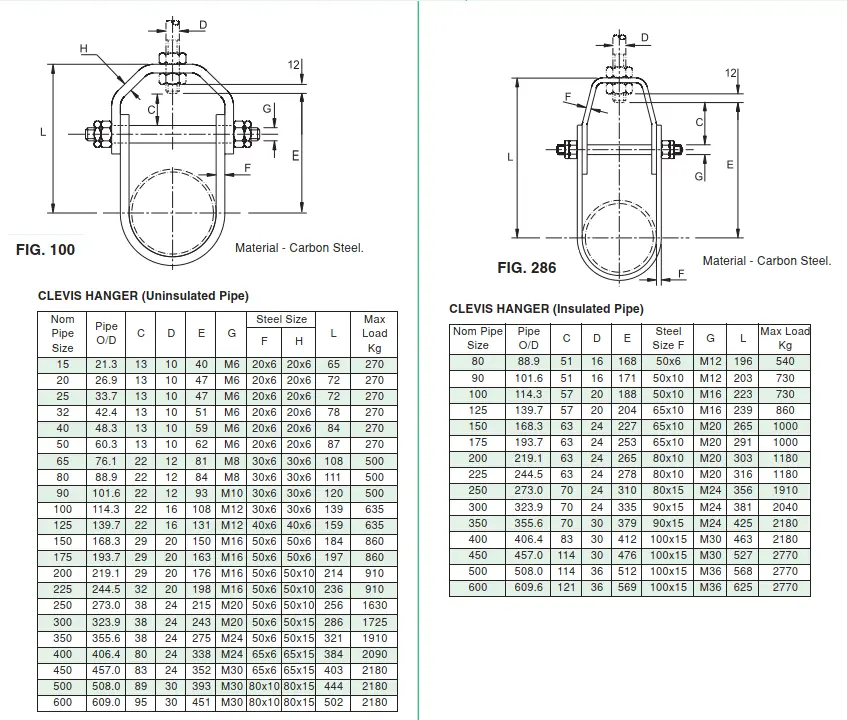
In general, clevis hangers are manufactured to support pipes from 1/2 inch through 24 inches. However, custom-designed clevis hanger sizes can be produced when required. The dimensions of each component may vary from one manufacturer to another. Accordingly, the load-carrying capability of the clevis hanger also varies. The following image from Carpenter and Paterson catalog is reproduced below to provide a reference about how much weight a clevis hanger can carry.
Fig. 1: Clevis Hanger Details from C&P Catalog
Clevis Hanger Specification
The following information needs to be mentioned to specify a clevis hanger for ordering.
Material of Construction
Figure Number as per the specific manufacturer (For example, Fig. 100 as per C&P catalog)
Nominal pipe size
Clevis Hanger Manufacturers
Some of the well-established and popular manufacturers of clevis hanger support are listed below:
Anvil International
Piping Technology and Products
Carpenter & Paterson
Taylor Pipe Supports
Globe Pipe Hanger Products
Oatey
Hilti
Buckaroos, Inc.
ERICO (nVent)
Empire Industries
Fischer International
Difference between Clevis Hanger and Pipe Clamp
While both clevis hangers and pipe clamps serve the purpose of supporting and suspending piping systems, there are notable differences between the two in terms of their design, functionality, and applications. Here are some key distinctions:
Clevis Hanger
Pipe Clamp
A clevis hanger consists of a U-shaped clevis and a threaded rod. The clevis has two holes, one for attaching the hanger to the supporting structure and the other for connecting the hanger to the threaded rod
A pipe clamp typically consists of a metal band or strap that wraps around the pipe and is secured using bolts or other fasteners. It may also have a cushioning material or lining to protect the pipe surface
Clevis hangers are typically attached to the supporting structure using bolts or other suitable means. They provide vertical support and allow for adjustment of the suspended pipe’s height
Pipe clamps directly wrap around the pipe and are fastened using bolts or other fasteners. They provide lateral support and are used to secure pipes to walls, beams, or other structural elements.
Clevis hangers primarily provide vertical support and suspension for pipes. They allow for some degree of movement and adjustment to accommodate thermal expansion, contraction, or system adjustments.
Pipe clamps are designed to secure pipes in place, preventing movement or vibration. They provide lateral support and help distribute the load along the pipe’s length.
Clevis Hanger vs Pipe Clamp
Vibration Measurement: Instruments, Units, and Applications Explained
Vibration measurement is the process of quantifying the magnitude, frequency, and direction of oscillatory motion in a physical system. This can be done using various sensors, such as accelerometers, to measure the vibrations in a particular object or structure.
Vibration measurements are important in a variety of industries, including automotive, aerospace, and civil engineering, as excessive vibration can cause damage to machinery and structures over time. By measuring vibrations, engineers and technicians can identify potential problems early on and take corrective actions to prevent further damage or failure.
Vibration measurements are typically analyzed using tools such as signal processing and spectral analysis to identify the root cause of the vibrations and develop solutions to mitigate them.
Requirements for Vibration Measurement
There are several reasons why we need to measure vibration:
Prevent damage: Excessive vibration can cause damage to machinery and structures over time. By measuring vibrations, engineers and technicians can identify potential problems early on and take corrective actions to prevent further damage or failure.
Improve performance: Vibration measurements can help engineers and technicians identify opportunities to improve the performance of a system. For example, by identifying the source of unwanted vibrations, they can make design changes or adjustments to reduce or eliminate those vibrations, which can lead to improved performance and efficiency.
Ensure safety: Vibrations can be hazardous to human health, and in some cases, can cause injury or even death. By measuring vibrations, engineers and technicians can ensure that structures and equipment are safe for people to use and operate.
Meet regulatory requirements: In some industries, there are regulatory requirements for vibration levels in equipment and structures. By measuring vibrations, engineers and technicians can ensure that they meet these requirements and avoid any legal or financial penalties.
Overall, vibration measurement is essential in many industries to ensure the safe, reliable, and efficient operation of machinery and structures
How is Vibration Measured?
Vibration can be measured using a variety of techniques, but the most common method is through the use of sensors called accelerometers. Accelerometers are devices that measure the acceleration of a vibrating object, which can then be used to calculate the vibration amplitude and frequency.
Accelerometers are typically attached to the surface of the object being measured using adhesive or mounting screws. They can be designed to measure vibration in one, two, or three dimensions, depending on the nature of the vibration being measured.
Once the accelerometer is attached to the object, it produces an electrical signal that is proportional to the acceleration of the object. This signal is then amplified and filtered to remove any noise or interference and then recorded or displayed on a computer or other data acquisition system.
Vibration measurements can be analyzed using various tools and techniques, including time-domain analysis, frequency-domain analysis, and statistical analysis. These techniques help engineers and technicians identify the characteristics of the vibration, such as the frequency, amplitude, and direction, and develop appropriate solutions to address any issues.
Measured vibration data can be used in several ways depending on the application and the specific parameters being measured. Here are some common ways to use vibration data:
Maintenance and monitoring: Vibration data can be used to monitor the condition of machinery and equipment (Learn more about vibration monitoring by clicking here) and to detect any changes in vibration that may indicate equipment failure or performance degradation. This helps to minimize downtime, improve equipment reliability, and optimize maintenance schedules.
Design and testing: Vibration data can be used in the design and testing of mechanical systems and structures to ensure that they are safe, durable, and reliable under various environmental and load conditions.
Performance optimization: Vibration data can be used to optimize the performance of machinery and equipment by identifying areas where vibration levels are high and implementing changes to reduce or eliminate the sources of vibration.
Quality control: Vibration data can be used in quality control processes to ensure that products meet the required specifications and do not have any defects or issues related to vibration.
Research and development: Vibration data can be used in research and development projects to better understand the behavior and performance of mechanical systems and structures under various conditions.
Vibration Measurement
Unit of Vibration Measurement
The unit of vibration measurement depends on the specific parameter being measured. The most common unit of vibration measurement is acceleration, which is typically measured in meters per second squared (m/s2) or g’s (where 1 g = 9.81 m/s2).
Other common units of vibration measurement include:
Velocity: measured in meters per second (m/s) or inches per second (in/s)
Displacement: measured in meters (m) or inches (in)
Frequency: measured in Hertz (Hz) or cycles per second (CPS)
Each of these units represents a different aspect of the vibration being measured. Acceleration measures the rate of change of velocity, velocity measures the rate of change of displacement, and displacement measures the amount of movement from a stationary position. Frequency represents the number of oscillations or cycles per unit of time.
It’s important to note that the unit of vibration measurement will depend on the specific application and the parameters being measured. Engineers and technicians will choose the appropriate unit of measurement based on the requirements of their particular application.
How to Quantify Vibration?
There are several ways to quantify vibration, depending on the specific application and the parameters being measured. Here are some common methods:
Amplitude: Amplitude is the measure of the maximum displacement, velocity, or acceleration of a vibrating object from its equilibrium position. It is typically measured in units such as meters (for displacement), meters per second (for velocity), or meters per second squared (for acceleration).
Frequency: Frequency is the number of oscillations or cycles per unit of time. It is typically measured in units such as Hertz (Hz) or cycles per second (CPS).
Power Spectral Density (PSD): PSD is a measure of the distribution of energy across different frequencies in a vibration signal. It is typically expressed in units such as g^2/Hz, where g is the acceleration due to gravity.
Root Mean Square (RMS): RMS is a measure of the average energy of a vibration signal over time. It is typically expressed in units such as g (for acceleration) or mm/s (for velocity).
Crest Factor: The crest factor is the ratio of the peak amplitude of a vibration signal to its RMS value. It is typically used to assess the severity of high-frequency vibration signals.
Kurtosis: Kurtosis is a measure of the peakedness of a vibration signal. It is typically used to assess the presence of high-frequency or impulsive vibration signals.
Vibration Measurement Instruments
There are several types of instruments used to measure vibration. Each vibration measuring tool has its own limitations and so it must be carefully selected. The most common instruments include:
Accelerometers: Accelerometers are the most commonly used instruments for measuring vibration. They measure the acceleration of a vibrating object, which can then be used to calculate the vibration amplitude and frequency.
Velometers: Velometers measure the velocity of a vibrating object. They are typically used to measure low-frequency vibrations.
Displacement probes: Displacement probes measure the displacement of a vibrating object. They are typically used to measure high-frequency vibrations.
Proximity probes: Proximity probes measure the distance between a vibrating object and a stationary surface. They are typically used to measure the vibration of rotating machinery.
Laser vibrometers: Laser vibrometers use laser beams to measure the vibrations of an object without physical contact. They are typically used to measure vibrations in delicate or hard-to-reach objects.
Tachometers: Tachometers measure the rotational speed of a shaft or motor. They are typically used to measure the vibration of rotating machinery.
Spectrum analyzers: Spectrum analyzers are used to analyze the frequency content of a vibration signal. They are typically used to identify the source of unwanted vibrations and develop appropriate solutions.
Applications of Vibration Measurement
Vibration measurement has a wide range of applications across various industries. Here are some examples:
Industrial machinery: Vibration measurement is commonly used in the maintenance and monitoring of industrial machinery to detect any changes in vibration that may indicate equipment failure or performance degradation. This helps to minimize downtime, improve equipment reliability, and optimize maintenance schedules.
Aerospace: Vibration measurement is critical in aerospace applications, where it is used to monitor the structural integrity of aircraft components and ensure that they remain within safe limits during operation.
Automotive: Vibration measurement is used in the design and testing of automobiles, where it is used to evaluate the ride comfort of the vehicle and to detect any potential issues with the suspension or steering systems.
Civil engineering: Vibration measurement is used in civil engineering applications, such as bridge and building design, to ensure that structures are safe and stable under various environmental and load conditions.
Medical devices: Vibration measurement is used in the development and testing of medical devices, such as surgical instruments and implantable devices, to ensure that they operate within safe limits and do not cause harm to patients.
Consumer electronics: Vibration measurement is used in the design and testing of consumer electronics, such as smartphones and laptops, to ensure that they are durable and reliable under various usage conditions.
Oil and Gas Industries
Industry Standards for Oil and Gas Vibration Measurement
There are several industry standards for piping vibration measurement, including:
API 618/API 674 – This standard specifies the vibration limits for reciprocating compressors and pumps used in the petroleum, petrochemical, and natural gas industries.
ISO 10816 – this standard provides guidelines for the measurement and evaluation of vibration in industrial machinery. It specifies the allowable vibration levels for various types of machines, including pumps, fans, and compressors.
ASME PTC 19.3 – this standard provides guidelines for the measurement of vibration in piping systems. It includes procedures for measuring vibration levels, identifying the sources of vibration, and evaluating the severity of vibration.
ANSI/HI 9.6.4 – this standard provides guidelines for the measurement and evaluation of vibration in centrifugal pumps. It specifies the allowable vibration levels for different pump types and operating conditions.
NEMA MG 1-2018 – this standard provides guidelines for the measurement and evaluation of vibration in electric motors. It specifies the allowable vibration levels for different motor types and operating conditions.
Energy Institute Guidelines
Overall, these industry standards provide guidelines for measuring and evaluating vibration in various types of machinery and equipment, including piping systems. They help to ensure that equipment is operating safely and reliably and that any potential issues related to vibration are identified and addressed in a timely manner
Vibration Meter
A vibration meter is a portable device that is used to measure the vibration of a mechanical system or structure. It typically consists of a sensor, display unit, and software for analyzing the vibration data.
The sensor is usually an accelerometer that is attached to the surface of the object being measured. It measures the acceleration of the object, which can then be used to calculate the vibration amplitude and frequency. Some vibration meters may also include other sensors, such as velocity sensors or displacement probes, to provide additional information about the vibration characteristics.
The display unit of a vibration meter typically shows the vibration measurement in real-time, allowing the operator to monitor the vibration levels and make any necessary adjustments. Some vibration meters may also include additional features, such as the ability to store and analyze vibration data over time, or the ability to connect to a computer or other data acquisition system for more detailed analysis.
Vibration meters are commonly used in the maintenance and monitoring of industrial machinery, where they are used to detect any changes in vibration that may indicate equipment failure or performance degradation. They are also used in various other industries, including aerospace, automotive, and civil engineering, to measure and analyze vibrations in machinery and structures.
Complete Guide to Epoxy Pipe Coating: Types, Applications, Pros and Cons, and Repair Methods
Epoxy pipe coating is a method of coating the inside of pipes, tanks, and other vessels with a layer of epoxy resin. This coating helps to protect the interior surfaces of the pipes from corrosion and chemical damage, as well as improve the flow of fluids through the pipes. The epoxy resin is applied to the interior surface of the pipe using a spray or brush, and it is allowed to cure and harden. The resulting coating is a smooth and durable layer that is resistant to chemicals and abrasion.
Epoxy pipe coating is commonly used in the oil and gas industry, as well as in water treatment plants and other industrial settings. It is also used in residential plumbing to improve the lifespan and performance of pipes.
Types of Epoxy Pipe Coatings
There are several types of epoxy pipe coatings, including:
Solvent-free epoxy coatings: These coatings do not contain solvents and are commonly used in potable water systems due to their low toxicity.
Solvent-based epoxy coatings: These coatings contain solvents and are used in applications where a faster cure time is needed.
Fusion-bonded epoxy coatings: These coatings are applied electrostatically and then melted onto the surface of the pipe to create a strong, durable bond.
Novolac epoxy coatings: These coatings are formulated to provide greater chemical resistance, making them ideal for use in harsh chemical environments.
High-temperature epoxy coatings: These coatings are designed to withstand high temperatures and are used in applications where the pipes will be exposed to extreme heat.
The type of epoxy coating used will depend on the specific application and the conditions the pipes will be exposed to
Applications of Epoxy Coatings
Epoxy pipe coatings have a wide range of applications in various industries, including:
Oil and gas industry: Epoxy coatings are used to protect pipelines from corrosion and chemical damage.
Water and wastewater treatment plants: Epoxy coatings are used to protect pipes and tanks from corrosion and chemical damage caused by the harsh chemicals used in the treatment process.
Chemical processing industry: Epoxy coatings are used to protect pipes, tanks, and other equipment from corrosion and chemical damage caused by the harsh chemicals used in the manufacturing process.
Food and beverage industry: Epoxy coatings are used to protect pipes and tanks used in food and beverage products from corrosion and contamination.
Residential plumbing: Epoxy coatings are used to protect and extend the life of pipes in residential plumbing systems.
Marine industry: Epoxy coatings are used to protect ships, offshore structures, and underwater pipelines from corrosion and damage caused by saltwater and other harsh marine environments.
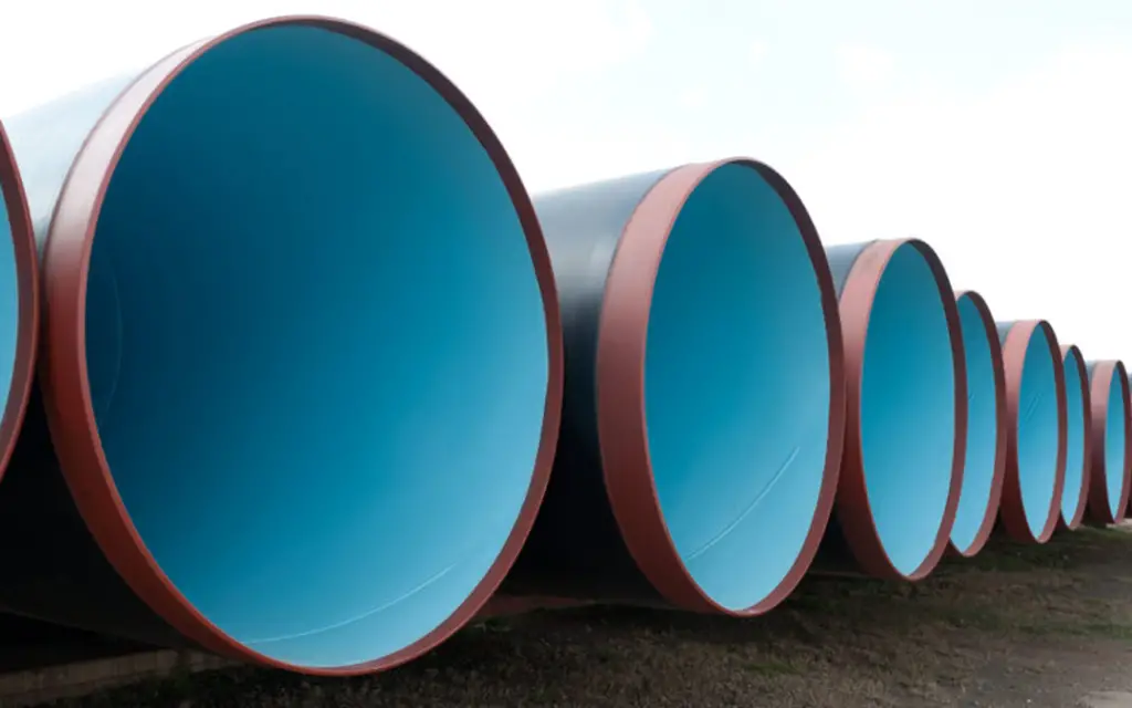
Overall, epoxy pipe coatings provide an effective solution for protecting pipes and other equipment from corrosion, chemical damage, and other forms of wear and tear. Fig. 1 (Image Credit: https://www.houstonpowdercoaters.com/) Below shows a typical example of Epoxy pipe Coatings.
Fig. 1: Examples of Epoxy Pipe Coatings
Steps for application of Epoxy Pipe Coatings
The application process for epoxy pipe coatings may vary depending on the specific product and application, so it’s important to follow the manufacturer’s instructions carefully. Overall, the application process for epoxy pipe coatings typically involves the following steps:
Surface preparation: The interior surface of the pipe must be thoroughly cleaned and prepared before the epoxy coating is applied. This typically involves sandblasting or using a wire brush to remove any rust, debris, or other contaminants that could interfere with the adhesion of the coating.
Mixing the epoxy: The two components of the epoxy coating (resin and hardener) must be mixed together according to the manufacturer’s instructions.
Application: The epoxy coating can be applied using a brush, roller, or spray equipment. The coating should be applied in a thin, even layer, and care should be taken to avoid any drips or uneven areas.
Curing: The epoxy coating must be allowed to cure according to the manufacturer’s instructions. This typically involves allowing the coating to dry for several hours or overnight, depending on the specific product.
Inspection: Once the coating has cured, it should be inspected for any defects or areas that may need touch-ups. Any imperfections should be corrected before the coating is put into service.
Technologies for Epoxy Coating of Pipelines
There are several technologies available for epoxy coating pipelines, each with its own advantages and disadvantages. Here are some of the best available technologies for epoxy coating pipelines:
Spray lining technology
This method involves using a high-pressure spray gun to apply an epoxy coating to the interior of the pipe. This method is fast and efficient, but it requires a high level of skill and experience to ensure an even coating.
Brush and roll technology
This method involves manually applying the epoxy coating to the interior of the pipe using brushes and rollers. This method is slower than spray lining but can be more precise and provide a thicker coating.
Spin casting technology
This method involves spinning the pipe at a high speed while spraying the epoxy coating onto the interior of the pipe. This method can produce a very even and uniform coating but can be more expensive than other methods.
Flood coating technology
This method involves flooding the pipe with liquid epoxy and allowing it to coat the interior of the pipe through gravity. This method is best suited for smaller-diameter pipes and can produce a very even and uniform coating.
Cured-in-place pipe (CIPP) lining
This method involves inserting a liner into the pipe and then curing it with heat or ultraviolet light, creating a new pipe within the old one. This method can be very effective for repairing damaged or corroded pipes and can also provide a protective epoxy coating.
Fusion Bonded Epoxy Pipe Coating
Fusion-bonded epoxy (FBE) pipe coating is a type of epoxy coating that is commonly used to protect steel pipes from corrosion. FBE coating is created by applying a thermosetting epoxy powder to the surface of the pipe and then melting and fusing the powder to the steel using a high-temperature curing process. This creates a seamless, durable coating that is highly resistant to corrosion and abrasion.
FBE pipe coating is commonly used in a variety of industries, including oil and gas, water and wastewater, and construction. It can be applied to pipes of varying sizes and shapes and is particularly effective in protecting pipelines that are exposed to harsh environments or corrosive substances.
Some of the benefits of FBE pipe coating include:
High corrosion resistance – FBE coating provides a highly effective barrier against corrosion, even in harsh environments.
Durable and long-lasting – FBE coating is highly durable and can last for several decades with proper maintenance.
Environmentally friendly – FBE coating is a solvent-free, environmentally friendly coating that does not emit harmful pollutants or chemicals.
Easy to apply – FBE coating can be applied using a variety of methods, including electrostatic spray, fluidized bed, and hot flocking.
Overall, FBE pipe coating is a popular and effective method for protecting steel pipes from corrosion and extending their lifespan.
Glass Flake Epoxy Pipe Coating
Glass flake epoxy pipe coating is a type of epoxy coating that incorporates small glass flakes into the coating material. The glass flakes serve as a reinforcing agent, providing additional strength and durability to the coating. The flakes also create a barrier that helps to prevent moisture and other corrosive substances from penetrating the surface of the coating and reaching the underlying steel pipe.
Glass flake epoxy pipe coating is particularly effective in protecting pipes that are exposed to harsh environments or corrosive substances. It is commonly used in industries such as oil and gas, chemical processing, and marine applications. Some of the benefits of glass flake epoxy pipe coating include:
High resistance to corrosion – Glass flake epoxy coating provides a highly effective barrier against corrosion, even in harsh environments.
Excellent adhesion – Glass flake epoxy coating has excellent adhesion to steel surfaces, ensuring that the coating stays in place and provides long-lasting protection.
Increased durability – The addition of glass flakes to the coating material provides additional strength and durability, making it more resistant to abrasion and impact damage.
Easy to apply – Glass flake epoxy coating can be applied using a variety of methods, including spray, brush, and roller.
Overall, glass flake epoxy pipe coating is a popular and effective method for protecting steel pipes from corrosion and extending their lifespan.
Epoxy Pipe Coating Price
The price of epoxy pipe coating can vary depending on several factors, such as the type of epoxy coating used, the size of the pipe, and the extent of the damage or corrosion. In general, the cost of epoxy pipe coating can range from $15 to $30 per linear foot of pipe, but this is only a rough estimate and the actual cost can be higher or lower depending on the specific project requirements.
Other factors that can affect the price of epoxy pipe coating include the cost of surface preparation, labor costs, and any additional services that may be required, such as inspection and testing. It’s important to get a detailed quote from a professional contractor to get an accurate estimate for your specific project.
Keep in mind that while epoxy pipe coating may seem expensive compared to other pipe repair methods, it can be a cost-effective solution in the long run as it can extend the life of the pipe and reduce the need for frequent repairs or replacement.
Epoxy Pipe Coating Failures
While epoxy pipe coatings are generally durable and effective at preventing corrosion, there are a few common types of epoxy pipe coating failures that can occur:
Adhesion failure: This occurs when the epoxy coating fails to properly adhere to the surface of the pipe, which can be caused by factors such as improper surface preparation or a poorly formulated coating. Adhesion failure can result in the coating peeling or flaking off, exposing the underlying steel surface to corrosion.
Blistering: This occurs when small bubbles or blisters form on the surface of the epoxy coating, which can be caused by improper surface preparation, moisture contamination, or excessive heat during curing.
Cracking: This occurs when the epoxy coating develops small cracks, which can be caused by factors such as thermal expansion and contraction, improper coating thickness, or exposure to chemicals.
If epoxy pipe coating failures occur, they can be repaired using the following methods:
Abrasive blasting: This involves removing the damaged coating and preparing the surface of the pipe by abrasive blasting to create a clean, rough surface for the new coating to adhere to.
Spot repair: This involves removing the damaged coating in the affected area and applying a new coating to that area only, rather than recoating the entire pipe.
Recoating: If the damage is extensive, it may be necessary to remove the entire coating and recoat the entire pipe.
It is important to work with a professional contractor who is experienced in epoxy pipe coating and repair to ensure that any coating failures are properly addressed and repaired.
Difference between Epoxy Pipe Coating and Epoxy Pipe Lining
Epoxy pipe coating and epoxy pipe lining are both methods for rehabilitating old or damaged pipes, but they differ in several ways.
Epoxy Pipe Coating:
Involves applying a layer of epoxy coating to the interior of the pipe
Typically used to repair smaller areas of damage or corrosion
Can be applied to pipes of varying sizes and shapes
Can improve the flow of fluids through the pipes
Can last for several decades if applied correctly
Can be less expensive than traditional pipe replacement methods
Epoxy Pipe Lining:
Involves creating a seamless, jointless liner inside the existing pipe using an epoxy resin
Typically used to rehabilitate longer sections of damaged or deteriorating pipe
Requires access points to be created to insert the epoxy liner
Can only be applied to pipes with a relatively simple shape and configuration
Can improve the structural integrity of the pipe and prevent leaks
Can last for several decades if installed correctly
Can be less expensive than traditional pipe replacement methods
In summary, epoxy pipe coating involves applying a layer of epoxy to the interior of the pipe, while epoxy pipe lining involves creating a seamless liner inside the existing pipe using an epoxy resin. Epoxy pipe coating can be used to repair smaller areas of damage, while epoxy pipe lining is typically used to rehabilitate longer sections of pipe. Both methods can improve the longevity and efficiency of pipes, and their suitability for a particular project depends on the extent and location of the damage, as well as the shape and configuration of the pipe.
Pros and Cons of Epoxy Pipe Lining/Coating
Pros of Epoxy Pipe Lining:
Cost-effective: Epoxy pipe lining is often less expensive than traditional pipe replacement methods, as it can be done without digging up the pipes or tearing down walls.
Fast installation: Epoxy pipe lining can be completed in a matter of hours or days, depending on the extent of the repairs needed.
Durable: Epoxy pipe lining creates a seamless, jointless, and corrosion-resistant liner that can last for several decades.
Improves flow: Epoxy pipe lining can improve the flow of fluids through the pipes, which can result in better efficiency and lower operating costs.
Environmentally friendly: Epoxy pipe lining is a green alternative to pipe replacement, as it does not require the disposal of old pipes or the use of new materials.
Cons of Epoxy Pipe Lining:
Limited application: Epoxy pipe lining may not be suitable for all types of pipes or damage. It works best for small to medium-sized pipes with simple shapes and relatively minor damage.
Temporary fix: While epoxy pipe lining is a durable solution, it is not a permanent fix. The lining will eventually need to be replaced or repaired.
Potential for air pockets: If the epoxy is not applied correctly, air pockets can form, which can compromise the effectiveness of the lining.
Risk of failure: Epoxy pipe lining can fail if it is not installed correctly or if the conditions inside the pipe are not suitable for the lining.
In conclusion, epoxy pipe lining is a cost-effective and durable alternative to traditional pipe replacement methods. However, it may not be suitable for all applications, and proper installation is critical to its success.
Epoxy Pipe Coating and Lining Companies
There are many companies that provide epoxy pipe coating and lining services, but some of the renowned companies in this field include:
SPT Pipe – SPT Pipe is a leading provider of epoxy pipe lining services for both commercial and residential properties.
Nu Flow Technologies – Nu Flow Technologies offers a range of pipe lining solutions, including epoxy pipe lining, for commercial and residential properties.
Perma-Liner Industries – Perma-Liner Industries specializes in trenchless pipe lining solutions, including epoxy pipe lining and coating, for a variety of industries.
Roto-Rooter – Roto-Rooter is a well-known plumbing and drain cleaning company that offers epoxy pipe lining and coating services for residential and commercial properties.
Flow-Liner Systems – Flow-Liner Systems provides epoxy pipe lining and coating solutions for pipes of various sizes and shapes, including underground and vertical pipes.
These are just a few examples of companies that provide epoxy pipe coating and lining services. When choosing a company for your project, it’s important to do your research and select a reputable, experienced company with a proven track record of success.
Types, Applications, and Selection of Diaphragm Valves
Diaphragm valves are an essential part of many industrial processes, and are commonly used in applications where precise control over fluid flow is required. These valves consist of a flexible diaphragm that separates the valve body from the fluid being controlled and are available in a variety of materials, sizes, and configurations. In this article, we will discuss the basic principles of diaphragm valves, their construction and working, types and applications, advantages and disadvantages, and maintenance requirements.
Construction and Working
Diaphragm valves consist of a valve body, which houses a flexible diaphragm, and a bonnet, which secures the diaphragm to the valve body. The diaphragm is usually made of rubber, neoprene, or other elastomers, and is designed to be flexible enough to deform under pressure, allowing fluid to pass through the valve. When the valve is closed, the diaphragm seals the valve body, preventing fluid from passing through.
The operation of a diaphragm valve is controlled by a mechanism that presses the diaphragm against the valve body, either opening or closing the valve. The most common type of mechanism used in diaphragm valves is the handwheel or actuator. The handwheel is connected to a stem, which is attached to the diaphragm, and when turned, moves the diaphragm up or down, opening or closing the valve. The actuator is a more complex mechanism that is controlled by an electrical signal or pneumatic pressure and is used in automated control systems.
Diaphragm Valve Parts
A diaphragm valve has the following components:
A strong and rigid Valve Body
A Bonnet to cover the top of the diaphragm valve
A Diaphragm
A Compressor to operate the diaphragm
Stem (Rising or non-rising type)
Actuator (Manual, Electric, Pneumatic, Hydraulic, or Thermal)
Position Indicators
Types of Diaphragm Valves
There are several types of diaphragm valves, each with its own unique design and application. They are classified based on valve construction and application.
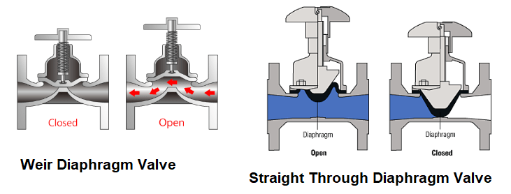
Based on valve body and diaphragm design, there are two types of diaphragm valves; Weir diaphragm valves and Straight through diaphragm valves. Fig. 1 (Pic Courtesy: https://www.globalspec.com/) shows a schematic of both types of diaphragm valves.
Weir Diaphragm Valves
Weir diaphragm valves are designed with a raised lip, or weir, around the edge of the valve body. The diaphragm is positioned over the weir, and when the valve is opened, the fluid flows over the weir and through the valve. This is the most popular design of diaphragm valves. Weir diaphragm valves are usually preferred for handling gases and clean and homogeneous liquids.
Straight through Diaphragm Valves
Straight-through diaphragm valves have a flat bottom valve body, with the diaphragm positioned directly over the fluid flow path. They have a comparatively short service life and are preferred for handling semi-solid media such as slurries, sludges, and viscous fluids.
Fig. 1: Weir and Straight through Diaphragm Valves
Based on the application, the following types of diaphragm valves are popular:
Sanitary Diaphragm Valves
Sanitary diaphragm valves are widely used in applications that need a high degree of fluid purity and cleanliness. Typical industries include winemaking, dairy, beverages, food, and pharmaceutical processing. By creating an aseptic environment for the flowing media, these type of diaphragm valves eliminates the thriving of bacteria, fungi, and viruses.
Biotech Valves
Biotech valves are special types of diaphragm valves that handle fluids containing microorganisms, cells, and other biological matter. These valves are mostly found in pipelines involving bioreactors, fermenters, filtration, and chromatography skids that are typically used in the biotechnology fields such as medicine, agriculture, the pharmaceutical industry, and food science.
Hygienic Valves
Hygienic valves are specifically designed diaphragm valves such as to eliminate the possibility of fluid stagnation. They are used to handle products intended for human consumption. Hygienic valves are widely used in the food and beverage industries.
Process Valves
This type of diaphragm valve is used to regulate the flow rates of liquid and gaseous fluids in process industries.
Zero Static Valves
Zero static valves are mainly used in the pharmaceutical industry. They are multi-port valves that allow process fluids to be transferred, drained, sampled, or diverted without inducing a major impact on critical systems such as Water for Injection (WFI) or Purified Water.
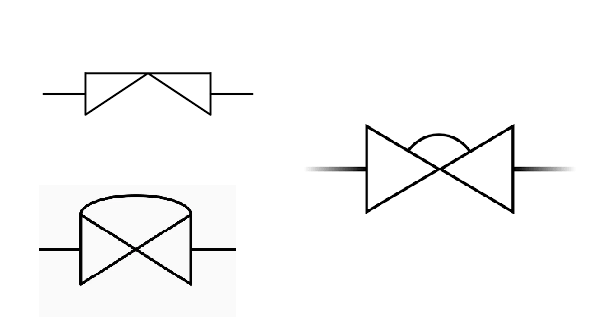
Diaphragm Valve Symbol
The specific symbol used for a diaphragm valve may vary depending on the standard being used and the specific application. In general, the diaphragm valve is denoted by any of the following symbols as mentioned in Fig. 2
Fig. 2: Diaphragm Valve Symbol
Materials of Construction of Diaphragm Valves
Diaphragm valves are available in a variety of materials of construction, depending on the specific application requirements. The most common materials used for diaphragm valves include:
PVC (Polyvinyl Chloride): PVC is a thermoplastic material that is commonly used for low-pressure applications. It is resistant to a wide range of chemicals and is relatively inexpensive. However, it has a limited temperature range and may become brittle over time.
CPVC (Chlorinated Polyvinyl Chloride): CPVC is a thermoplastic material that is similar to PVC but has better resistance to high temperatures and corrosive chemicals. It is commonly used for industrial applications that require a higher level of chemical resistance.
PP (Polypropylene): PP is a thermoplastic material that is highly resistant to a wide range of chemicals and has a relatively high-temperature range. It is commonly used for applications involving corrosive liquids and gases.
PVDF (Polyvinylidene Fluoride): PVDF is a thermoplastic material that is highly resistant to a wide range of chemicals and has a high-temperature range. It is commonly used for applications involving highly corrosive and aggressive fluids.
Stainless Steel: Stainless steel is a highly durable and corrosion-resistant material that is commonly used for high-pressure and high-temperature applications. It is available in a range of grades and alloys to meet specific application requirements.
Hastelloy: Hastelloy is a nickel-based alloy that is highly resistant to corrosion and chemical attack. It is commonly used for applications involving highly corrosive and aggressive fluids.
Titanium: Titanium is a highly durable and corrosion-resistant metal that is commonly used for applications involving highly corrosive and aggressive fluids. It is also lightweight and has a high strength-to-weight ratio.
In addition to the materials listed above, diaphragm valves can also be constructed from other materials such as brass, bronze, stainless steel, cast iron, ductile iron, cast steel, and other metals, depending on the specific application requirements. The selection of the materials of construction for diaphragm valves is critical to ensure proper operation and longevity in the specific application.
Selection of a Diaphragm Valve
When selecting a diaphragm valve, there are several important parameters that should be considered to ensure that the valve is suitable for the specific application. Some of the key parameters to consider when selecting a diaphragm valve include:
Valve size: The size of the valve should be chosen based on the flow rate and pressure requirements of the application. Diaphragm valves are available in a range of sizes, from small valves suitable for laboratory use to large valves for industrial applications.
Materials of construction: The materials used to construct the valve should be selected based on the specific application requirements. Factors to consider include the fluid being handled, the temperature and pressure of the application, and the potential for corrosion or chemical attack.
Diaphragm material: The material used for the diaphragm should be selected based on the specific fluid being handled and the pressure and temperature of the application. Common diaphragm materials include rubber, PTFE, and other plastics.
Valve actuation: Diaphragm valves can be manually operated or automated. The method of actuation should be chosen based on the specific application requirements, including the frequency of operation and the need for precision control.
End connections: The end connections of the valve should be selected based on the specific piping configuration of the application. Diaphragm valves are available with a range of end connections, including threaded, flanged, and tri-clamp connections.
Flow control: The valve should be selected based on the specific flow control requirements of the application. Some diaphragm valves are designed for precise flow control, while others are designed for on/off applications.
Maintenance and repair: The valve should be selected based on its ease of maintenance and repair. Diaphragm valves should be easy to disassemble and reassemble for cleaning and maintenance, and replacement parts should be readily available.
By considering these parameters, it is possible to select a diaphragm valve that is well-suited for the specific application, ensuring optimal performance and longevity.
Applications of Diaphragm Valves
Diaphragm valves are commonly used in a variety of industries, including pharmaceuticals, food and beverage, chemical processing, and water treatment. They are used in applications where precise control over fluid flow is required, and where contamination of the fluid must be minimized. Some of the most common applications of diaphragm valves include:
Pharmaceutical Manufacturing: Diaphragm valves are used in pharmaceutical manufacturing to control the flow of fluids during the production of drugs and other pharmaceutical products. They are used to control the flow of liquids and gases and to prevent contamination of the product by foreign particles.
Food and Beverage Processing: Diaphragm valves are used in food and beverage processing to control the flow of fluids during the production of food and beverages. They are used to control the flow of liquids and gases and to prevent contamination of the product by bacteria and other contaminants.
Chemical Processing: Diaphragm valves are used in chemical processing to control the flow of chemicals during the production of various chemicals and compounds. They are used to control the flow of highly corrosive and toxic substances and to prevent contamination of the environment and personnel.
Water Treatment: Diaphragm valves are used in water treatment plants to control the flow of water and other liquids during the treatment process. They are used to control the flow of chemicals and other additives and to prevent contamination of the water supply.
Advantages and Disadvantages
Diaphragm valves offer several advantages over other types of valves, including:
Precise Flow Control: Diaphragm valves offer precise control over fluid flow, making them ideal for applications where accurate flow rates are critical.
Low Maintenance: Diaphragm valves are easy to maintain, requiring minimal maintenance and replacement parts.
Corrosion Resistance: Diaphragm valves are available in a variety of materials, including plastic and stainless steel, which offer excellent corrosion resistance.
Minimal Pressure Drop: Diaphragm valves have a minimal pressure drop across the valve, which means they can be used in applications where high flow rates are required.
However, diaphragm valves also have some disadvantages, including:
Limited Temperature Range: Diaphragm valves are typically not suitable for use in high-temperature applications, as the diaphragm material may degrade.
Limited Pressure Range: Diaphragm valves may not be suitable for use in high-pressure applications, as the diaphragm may rupture.
Limited Flow Capacity: Diaphragm valves may not be suitable for applications requiring high flow rates, as the valve body may become blocked or the diaphragm may rupture.
Maintenance Requirements
Diaphragm valves are generally low-maintenance, requiring only periodic cleaning and inspection. The diaphragm should be inspected regularly for signs of wear or damage and should be replaced as needed. The valve body should be cleaned periodically to remove any debris or buildup that may interfere with the operation of the valve. In addition, any actuator or control mechanism should be inspected and tested regularly to ensure proper operation.
Leading manufacturers of Diaphragm Valves
There are several leading manufacturers of diaphragm valves, each with its own unique product offerings and strengths. Some of the top manufacturers of diaphragm valves include:
Gemu: Gemu is a German-based company that specializes in the manufacture of high-quality diaphragm valves for a wide range of applications. Their products are known for their durability, reliability, and precision.
Saunders: Saunders is a UK-based company that produces a range of diaphragm valves for applications in industries such as chemical processing, pharmaceuticals, and water treatment. Their valves are known for their high performance, long service life, and ease of maintenance.
GF Piping Systems: GF Piping Systems is a Swiss-based company that offers a comprehensive range of diaphragm valves for industrial applications. Their valves are known for their excellent chemical resistance, easy maintenance, and long service life.
Aquasyn: Aquasyn is a US-based company that specializes in the manufacture of diaphragm valves for the biopharmaceutical industry. Their valves are designed for high-purity applications and are known for their exceptional cleanliness, reliability, and ease of maintenance.
Alfa Laval: Alfa Laval is a Swedish-based company that offers a range of diaphragm valves for use in industries such as food and beverage, pharmaceuticals, and chemicals. Their valves are known for their high performance, reliability, and ease of installation.
These are just a few examples of the leading manufacturers of diaphragm valves. When selecting a diaphragm valve supplier, it is important to consider factors such as product quality, reputation, service and support, and overall value for money.
Diaphragm Valve Price
The price of a diaphragm valve can vary widely depending on several factors, including the size and type of the valve, the materials of construction, and the manufacturer. In general, smaller diaphragm valves suitable for laboratory or research applications may cost a few hundred dollars, while larger industrial diaphragm valves may cost several thousand dollars or more.
Additionally, automated or electronically actuated diaphragm valves may cost more than manually operated valves, and valves constructed from specialty materials may also carry a premium price tag.
It’s important to keep in mind that the cost of a diaphragm valve should not be the only factor considered when selecting a valve. It’s also important to consider the performance, reliability, and longevity of the valve, as well as the cost of maintenance and any associated equipment or installation costs.
Overall, it’s best to work with a reputable supplier who can help you select a diaphragm valve that meets your specific application requirements and budget.
Conclusion
Diaphragm valves are a versatile and reliable type of valve that is used in a variety of industrial applications. They offer precise control over fluid flow, are easy to maintain, and are available in a variety of materials and configurations. While they may not be suitable for use in high-temperature or high-pressure applications, they are an ideal choice for applications requiring precise control over fluid flow and low maintenance requirements. By understanding the basic principles of diaphragm valves, their construction and working, types and applications, advantages and disadvantages, and maintenance requirements, industrial professionals can select and operate these valves effectively to meet their specific process needs.
What is a Multiport Selector Valve or MSV? Importance of MSV Skids
A multiport selector valve (MSV) is a type of rotary valve that is designed to divert the flow of a fluid or gas into different lines or process streams. It has multiple ports that can be selectively opened or closed to direct the fluid or gas flow to different outlets.
MSVs are commonly used in industrial applications where multiple process streams need to be controlled or where different fluids or gases need to be mixed or separated. For example, MSVs are used in the oil and gas industry to control the flow of oil, gas, and water in a production well, or in chemical processing plants to mix different chemicals or to direct process streams to different equipment.
MSVs are available in a variety of designs, including two-way, three-way, and four-way configurations, depending on the number of ports required. They are typically operated manually or by using automated control systems, such as pneumatic or electric actuators.
Multiport Selector Valve Functions
Overall, MSVs are an important component of process control systems and are widely used in various industries to control the flow of fluids or gases in a safe and efficient manner.
Multiport selector valves (MSVs) serve several important functions in the oil and gas industry, including:
Flow Control: MSVs are used to control the flow of fluids and gases in production facilities and pipeline systems. By selecting different flow paths and configurations, MSVs can direct the flow of fluids and gases to specific destinations, optimize the production efficiency, and minimize downtime.
Pressure Control: MSVs can also be used to control pressure in production facilities and pipeline systems. By adjusting the flow paths and configurations, MSVs can help maintain consistent pressure levels and prevent overpressure or underpressure conditions.
Fluid and Gas Sampling: MSVs can be equipped with sampling ports and connections for fluid and gas sampling. These sampling ports can be used to collect samples for analysis and monitoring of process conditions.
Product Separation: MSVs can be used to separate different products in production facilities, such as oil and gas. By directing the flow of fluids and gases through different paths, MSVs can separate different products and prevent contamination.
Maintenance: MSVs can be used to isolate different sections of the pipeline or production facility for maintenance and repair. By directing the flow of fluids and gases through different paths, MSVs can isolate specific sections of the system and allow for maintenance and repair without affecting the entire system.
Overall, MSVs play a critical role in flow control and process optimization in the oil and gas industry, providing flexible and precise control of fluid and gas flow in production facilities and pipeline systems.
Applications of MSVs in the Oil and Gas Industry
Multiport selector valves (MSVs) are widely used in the oil and gas industry for various applications, including:
Well Testing: MSVs are used in well testing operations to divert the flow of oil, gas, and water from the wellbore to different process streams or equipment. This allows operators to measure the production rates of each fluid and optimize the well production.
Production Separation: MSVs are used to separate oil, gas, and water during the production process. The valve is used to direct the flow of each fluid to different processing equipment, such as separators, heaters, and pumps.
Gas Lift Systems: MSVs are used in gas lift systems to control the injection of gas into the wellbore. The valve is used to divert the flow of gas to different injection points in the wellbore to optimize the lifting process.
Pipeline Pigging: MSVs are used in pipeline pigging operations to control the flow of cleaning pigs through the pipeline. The valve is used to divert the flow of the cleaning fluid and the pig to different sections of the pipeline.
Chemical Injection: MSVs are used in chemical injection systems to control the flow of chemicals into the production stream. The valve is used to divert the flow of the chemical to different injection points in the production stream.
Overall, MSVs play a critical role in the oil and gas industry by providing efficient and reliable control of fluid flow in various applications. Fig. 1 Below shows a typical MSV Skid.
Fig. 1: Example of MSV Skids
Working Principle of a Multiport Selector Valve
A multiport selector valve (MSV) works by diverting the flow of a fluid or gas from one inlet port to one or more outlet ports. The valve typically consists of a cylindrical body with multiple ports and a rotating plug or spool that selectively connects the inlet and outlet ports.
The plug or spool has multiple channels or passages that can be selectively aligned with the ports in the valve body. By rotating the plug or spool, the operator can control the flow direction and the destination of the fluid or gas.
When the plug or spool is rotated, it aligns with the selected outlet port, allowing the fluid or gas to flow through the valve and into the desired destination. The other outlet ports are closed off, preventing any flow in those directions.
MSVs can be operated manually or using automated control systems, such as pneumatic or electric actuators. In manual operation, the operator rotates the plug or spool using a handle or lever, while in automated operation, the actuator rotates the plug or spool in response to a signal from a controller.
The design and operation of MSVs may vary depending on the application and the specific requirements of the process. However, the basic principle of diverting the flow of a fluid or gas from one inlet port to one or more outlet ports remains the same.
What is an MSV Skid?
An MSV skid is a pre-engineered and pre-fabricated assembly that contains one or more multiport selector valves (MSVs) along with associated piping, instrumentation, and control systems. The skid is designed to be installed and connected to a pipeline or process system to provide efficient and reliable flow control.
MSV skids are commonly used in the oil and gas industry, particularly in production facilities and pipeline systems, to provide a compact and standardized solution for flow control. The skid can be designed to accommodate multiple MSVs, each with different configurations and sizes, depending on the specific requirements of the process.
The skid typically includes all the necessary components for MSV operation, including the valve, actuator, positioner, pressure gauges, and control panel. The skid may also include additional components, such as filters, regulators, and relief valves, to ensure proper operation and protection of the MSV and the downstream equipment.
MSV skids are designed to be modular and easy to install, reducing the installation time and cost compared to traditional field fabrication. The skids can be customized to meet the specific requirements of the process and can be easily integrated with other equipment and control systems.
Overall, MSV skids provide an efficient and cost-effective solution for flow control in the oil and gas industry, allowing for reliable and precise control of fluid and gas flow in production facilities and pipeline systems.
Advantages of MSV Skids
MSV skids offer several advantages in the oil and gas industry, including:
Standardization: MSV skids are pre-engineered and pre-fabricated, which allows for a standardized solution for flow control. Standardization ensures that the skids are designed, manufactured, and installed consistently, reducing the risk of errors and improving the reliability and efficiency of the system.
Modular Design: MSV skids are designed to be modular, allowing for easy installation and integration with other equipment and control systems. The modular design also enables the skids to be customized to meet specific requirements and easily modified or expanded as the process needs change.
Reduced Installation Time and Cost: MSV skids are pre-fabricated and tested in a controlled environment, reducing the installation time and cost compared to traditional field fabrication. The skids can be installed quickly and easily, minimizing downtime and improving operational efficiency.
Improved Quality Control: MSV skids are manufactured and tested in a controlled environment, ensuring consistent quality and reliability of the system. The skids undergo rigorous testing and inspection to ensure proper operation and compliance with industry standards and regulations.
Precise Flow Control: MSV skids provide precise and reliable flow control, allowing for accurate measurement and optimization of fluid and gas flow in production facilities and pipeline systems. The skids can be designed to accommodate multiple MSVs, each with different configurations and sizes, providing flexible and precise control of the flow.
Overall, MSV skids offer a cost-effective, reliable, and efficient solution for flow control in the oil and gas industry, allowing for precise and flexible control of fluid and gas flow in production facilities and pipeline systems.
Disadvantages of Multiport Selector Valves
While MSV skids offer many advantages for flow control in the oil and gas industry, there are also some potential disadvantages to consider:
Size Limitations: MSV skids are typically designed for smaller to mid-size pipelines and processes. For larger pipelines or processes, multiple MSV skids may be required, which can increase the complexity and cost of the system.
Maintenance: MSV skids require regular maintenance and inspection to ensure proper operation and prevent downtime. Maintenance can be more complex than traditional manual valves and may require specialized training or equipment.
Customization: While MSV skids can be customized to meet specific process requirements, the cost and complexity of customization can increase significantly. Customization may also affect the standardization and modularity of the skid, reducing some of the advantages mentioned earlier.
Cost: MSV skids can be more expensive than traditional manual valves, especially for smaller pipelines or processes. The cost may be justified by improved efficiency, reduced installation time, and increased reliability, but it is important to consider the overall cost-benefit analysis for each specific application.
Overall, the disadvantages of MSV skids are relatively minor compared to the benefits they can provide in terms of efficiency, reliability, and control. However, it is important to carefully evaluate the specific requirements of the process and consider the advantages and disadvantages of MSV skids in comparison to other flow control solutions.
MSV Skid Manufacturers
There are several companies that manufacture MSV skids for the oil and gas industry. Some of the renowned MSV skid manufacturers include:
Cameron
FMC Technologies
Emerson
Schlumberger
GE Oil and Gas
ABB
Yokogawa
Siemens
Honeywell
TechnipFMC
These companies have a strong reputation in the industry for providing high-quality MSV skids and related equipment and services. However, it is important to evaluate the specific requirements of the process and compare the capabilities and pricing of each manufacturer before making a decision.
Vibration Absorbers: Types, Working, Specification, Applications, and Advantages
Vibration is a common problem in many mechanical systems, including machinery, vehicles, and buildings. Vibrations can cause excessive noise, wear and tear on mechanical components, and even failure of the system. One way to control vibration is through the use of a vibration absorber. In this article, we will discuss what a vibration absorber is, how it works, and its various applications.
What is a Vibration Absorber?
A vibration absorber is a device designed to reduce the amplitude of vibrations in a mechanical system. It consists of a mass-spring system that is tuned to a specific frequency. When the system vibrates at this frequency, the vibration absorber absorbs the energy and reduces the amplitude of the vibrations.
The mass-spring system of a vibration absorber typically consists of a mass, which is the component that moves in response to the vibration, and a spring, which provides the restoring force that opposes the motion of the mass. The spring can be a mechanical spring, such as a coil spring, or it can be a non-mechanical spring, such as a pneumatic or hydraulic spring.
How Does a Vibration Absorber Work?
The basic principle behind a vibration absorber is the phenomenon of resonance. Resonance occurs when the frequency of the vibration is equal to the natural frequency of the mass-spring system. At resonance, the amplitude of the vibration can be very high, which can cause damage to the mechanical system.
The vibration absorber is designed to reduce the amplitude of the vibration by introducing an out-of-phase vibration that cancels out the original vibration. This is accomplished by tuning the natural frequency of the mass-spring system to be slightly lower than the frequency of the vibration. When the vibration absorber is activated, it introduces an out-of-phase vibration that cancels out the original vibration, reducing the amplitude of the vibration.
Applications of Vibration Absorbers
Vibration absorbers are used in a wide range of mechanical systems to control vibration and reduce the risk of damage or failure. Some common applications of vibration absorbers include:
Machinery: Vibration absorbers are commonly used in machinery to reduce vibration and noise. They are often used in engines, pumps, compressors, and other rotating equipment.
Vehicles: Vibration absorbers are used in vehicles to improve ride comfort and reduce the risk of damage to the vehicle. They are commonly used in cars, trucks, buses, and trains.
Buildings: Vibration absorbers are used in buildings to reduce the risk of damage from seismic activity, wind, or other sources of vibration. They are often used in tall buildings, bridges, and other structures.
Aerospace: Vibration absorbers are used in aerospace applications to reduce the vibration and noise generated by aircraft engines, turbines, and other components.
Design Considerations for Vibration Absorbers
The design of a vibration absorber depends on the specific application and the requirements of the mechanical system. Some key design considerations include:
Natural Frequency: The natural frequency of the mass-spring system must be tuned to be slightly lower than the frequency of the vibration that is to be absorbed. The natural frequency can be adjusted by changing the mass or the stiffness of the spring.
Damping: Damping is the ability of the system to dissipate energy and reduce the amplitude of the vibration. Damping can be provided by adding a damping material, such as a viscoelastic material, to the system.
Mass: The mass of the vibration absorber should be sufficient to provide the required damping and to resist the forces generated by the vibration. However, the mass should not be too large, as this can increase the inertia of the system and reduce its effectiveness.
Installation: The vibration absorber should be installed in a location where it can effectively absorb the vibration. The location should be chosen based on the location of the vibration source and the natural frequency of the mechanical system.
Temperature: The temperature of the environment in which the vibration absorber will be installed must be taken into account in the design. Changes in temperature can affect the stiffness of the spring and the damping material, which can affect the performance of the vibration absorber.
Types of Vibration Absorbers
There are several types of vibration absorbers that are used in mechanical systems. Some common types include:
Tuned Mass Damper (TMD): A tuned mass damper is a type of vibration absorber that consists of a mass-spring system that is tuned to the frequency of the vibration that is to be absorbed. TMDs are commonly used in buildings and bridges to reduce the effects of wind and seismic activity.
Fluid Viscous Damper (FVD): A fluid viscous damper is a type of vibration absorber that uses a fluid, such as oil or water, to provide damping. FVDs are commonly used in buildings and bridges to reduce the effects of wind and seismic activity.
Tuned Liquid Damper (TLD): A tuned liquid damper is a type of vibration absorber that uses a liquid, such as water, to provide damping. TLDs are commonly used in buildings and bridges to reduce the effects of wind and seismic activity.
Active Vibration Control (AVC): Active vibration control is a type of vibration control that uses sensors and actuators to actively control the vibration of a mechanical system. AVCs are commonly used in aircraft and spacecraft to reduce the effects of engine vibration.
Advantages of Vibration Absorbers
There are several advantages to using vibration absorbers in mechanical systems. Some of the main advantages include:
Reduced Vibration: Vibration absorbers can effectively reduce the amplitude of vibrations in a mechanical system, which can reduce the risk of damage or failure.
Improved Comfort: Vibration absorbers can improve ride comfort in vehicles and reduce the noise generated by machinery and other mechanical systems.
Increased Safety: Vibration absorbers can increase the safety of buildings and bridges by reducing the risk of damage from wind and seismic activity.
Cost-effective: Vibration absorbers can be a cost-effective solution for controlling vibration in mechanical systems, as they can be designed to provide the required damping and stiffness at a lower cost than other solutions.
Specifying a Vibration Absorber for Purchasing
When purchasing vibration absorbers, it is important to specify certain key parameters to ensure that the absorber is suitable for the intended application. Some of the parameters to consider include:
Frequency range: The frequency range of the vibration absorber should be specified to ensure that it is compatible with the frequency of the vibration that needs to be absorbed. The frequency range should be selected based on the natural frequency of the mechanical system and the frequency of the vibration source.
Damping coefficient: The damping coefficient of the vibration absorber should be specified to ensure that it provides sufficient damping to effectively absorb the vibration. The damping coefficient should be selected based on the level of damping required for the specific application.
Load capacity: The load capacity of the vibration absorber should be specified to ensure that it can support the weight of the mechanical system. The load capacity should be selected based on the weight of the mechanical system and any additional loads that may be applied.
Installation location: The installation location of the vibration absorber should be specified to ensure that it is installed in a location where it can effectively absorb the vibration. The location should be chosen based on the location of the vibration source and the natural frequency of the mechanical system.
Temperature range: The temperature range of the vibration absorber should be specified to ensure that it is suitable for the environment in which it will be installed. Changes in temperature can affect the stiffness of the spring and the damping material, which can affect the performance of the vibration absorber.
Other parameters that need to be mentioned are
Size and Weight of Absorbers
Vibration Type and Environment
The precision of the system
By specifying these parameters when purchasing vibration absorbers, you can ensure that you select a product that is suitable for your specific application and will effectively absorb the vibration in your mechanical system.
Difference between a Vibration Absorber and a Vibration Dampener
The terms “vibration absorber” and “vibration dampener” are often used interchangeably, but there is a subtle difference between the two.
A vibration absorber is a device that is used to absorb or reduce the amplitude of vibration in a mechanical system. The absorber is designed to reduce the amount of energy that is transmitted from the vibrating source to the rest of the mechanical system. Vibration absorbers are typically designed to have a resonant frequency that matches the frequency of the vibration that is to be absorbed. This allows the absorber to effectively reduce the amplitude of the vibration by dissipating the energy through the use of damping materials.
On the other hand, a vibration dampener is a device that is used to dampen or reduce the duration of vibration in a mechanical system. The dampener is designed to reduce the amount of energy that is stored in the vibrating system, which reduces the duration of the vibration. Vibration dampeners are typically designed to have a high damping coefficient, which allows them to dissipate the energy of the vibration quickly.
In summary, the main difference between vibration absorbers and vibration dampeners is that absorbers are designed to reduce the amplitude of vibration, while dampeners are designed to reduce the duration of vibration. Both types of devices are used to control vibration in mechanical systems and can be used in conjunction with each other for optimal vibration control.
Leading Vibration Absorber Manufacturers
There are several manufacturers of vibration absorbers that are recognized for their high-quality products and innovative solutions. Here are some of the leading manufacturers in the industry:
Enidine: Enidine is a leading manufacturer of vibration isolation and shock absorption products. They offer a wide range of products, including wire rope isolators, shock absorbers, and hydraulic vibration isolators. Their products are used in a variety of industries, including aerospace, defense, and industrial applications.
LORD Corporation: LORD Corporation is a global technology and manufacturing company that specializes in vibration control and noise reduction solutions. Their product portfolio includes vibration isolators, shock and vibration mounts, and damper systems. LORD Corporation’s products are used in applications such as automotive, aerospace, and industrial machinery.
Trelleborg: Trelleborg is a world leader in engineered polymer solutions that help to seal, damp, and protect critical applications in demanding environments. Their vibration isolation products include mounts, bushings, and isolators for applications such as industrial machinery, transportation, and marine.
Fabreeka: Fabreeka is a leading manufacturer of vibration isolation and shock control products. Their product line includes vibration pads, vibration isolators, and shock absorbers for use in industries such as construction, power generation, and heavy equipment.
Mason Industries: Mason Industries is a manufacturer of noise and vibration control products. They offer a range of products including vibration isolators, spring mounts, and noise control solutions for a variety of industries including HVAC, power generation, and marine.
These manufacturers are recognized for their high-quality products and innovative solutions. When selecting a vibration absorber, it is important to consider the specific needs of your application and to choose a manufacturer that has a proven track record of delivering reliable, effective products.
Conclusion
Vibration absorbers are an effective way to control vibration in mechanical systems and reduce the risk of damage or failure. They can be used in a wide range of applications, including machinery, vehicles, buildings, and aerospace. The design of a vibration absorber depends on the specific requirements of the mechanical system, including the natural frequency, damping, mass, and installation location. By effectively reducing vibration, vibration absorbers can improve ride comfort, reduce noise, and increase safety, making them an important component of many mechanical systems.