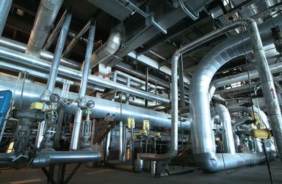
Heat exchangers play a critical role in various industrial processes, including power generation, chemical production, HVAC systems, Oil and gas industries, and many more. These devices facilitate efficient heat transfer between two fluids, ensuring optimal performance and energy efficiency. However, over time, heat exchangers are prone to a common problem known as fouling. Fouling refers to the accumulation of unwanted deposits or contaminants on the heat exchanger surfaces, leading to decreased efficiency, increased energy consumption, and potential equipment failures. In this article, we delve into the intricacies of heat exchanger fouling, exploring its causes, consequences, and mitigation strategies.
Understanding Heat Exchanger Fouling
Heat exchanger fouling occurs when unwanted substances deposit and adhere to the heat transfer surfaces, inhibiting heat exchange between the two fluids. These deposits can be categorized into various types, including scales, sediment, corrosion products, organic matter, and biological growth. The formation of fouling layers is influenced by factors such as fluid composition, temperature, pressure, velocity, and residence time.
Causes of Heat Exchanger Fouling/ Types of Heat Exchanger Fouling
Several factors contribute to the formation of fouling deposits in heat exchangers. Some common causes include:
Scaling:
Scale deposits result from the precipitation and crystallization of minerals, such as calcium carbonate and calcium sulfate, present in the fluid. Scaling is particularly common in processes involving hard water or high-temperature applications.
Sedimentation:
Particles suspended in the fluid, such as rust, debris, or solid contaminants, can settle and accumulate on heat exchanger surfaces over time, impeding heat transfer.
Corrosion:
Corrosive reactions within the fluid can lead to the formation of corrosion products, which can deposit on heat exchanger surfaces. It occurs when the metal surfaces of the exchanger are exposed to corrosive substances, such as oxygen, acids, or chemicals in the fluid being processed. Corrosion can weaken the metal and create rough surfaces that promote further fouling. Corrosion is often intensified by factors like elevated temperatures, the presence of impurities, or inappropriate material selection.
Organic/Biological fouling:
Organic matter, such as algae, biofilms, slime layers, fungi, bacteria, or oil residues, can adhere to the heat exchanger surfaces. These deposits promote further microbial growth, resulting in biofouling and additional heat transfer limitations. Biological fouling is common in cooling water systems, especially those exposed to natural water sources.
Particulate fouling:
Particles suspended in the fluid can deposit on the heat exchanger surfaces and form a layer of fouling. These particles can include dust, dirt, rust, sediment, or other solid contaminants present in the fluid. Particulate fouling can reduce heat transfer and increase pressure drop across the exchanger.
Chemical fouling:
Chemical reactions can result in the formation of unwanted deposits on the heat exchanger surfaces. For example, reactions between certain chemicals or fluids can produce solids that deposit on the heat transfer surfaces over time.
Soot fouling:
Soot is a byproduct of incomplete combustion in systems that burn fossil fuels. It can accumulate on heat transfer surfaces, especially in boilers, furnaces, or exhaust gas heat exchangers. Soot fouling reduces heat transfer efficiency and increases the risk of equipment malfunction.
Asphaltene fouling:
Asphaltene fouling occurs when heavy hydrocarbons, known as asphaltenes, present in crude oil or petroleum-based fluids, precipitate and deposit on heat exchanger surfaces. This type of fouling is common in oil refining and can lead to significant operational issues and reduced throughput.
Ice fouling:
In certain applications, such as refrigeration or air conditioning systems, the presence of moisture can lead to the formation of ice on heat exchanger surfaces. Ice fouling reduces heat transfer efficiency and increases energy consumption.
Polymerization fouling:
Polymerization fouling occurs when certain organic compounds in the fluid being processed undergo polymerization reactions and form sticky or solid deposits on heat transfer surfaces. This type of fouling is commonly observed in chemical processing industries.
Foaming fouling:
Foaming can occur when surfactants or substances that promote the formation of bubbles are present in the fluid. Foaming can lead to the accumulation of foam on heat exchanger surfaces, reducing heat transfer efficiency and increasing pressure drop.
Manganese dioxide fouling:
Manganese dioxide fouling is specific to systems that handle water containing manganese compounds. Under certain conditions, manganese dioxide can precipitate and form deposits on heat transfer surfaces, leading to reduced heat transfer efficiency.
Silica fouling:
Silica fouling occurs when dissolved silica in the fluid precipitates and forms deposits on heat exchanger surfaces. This type of fouling is common in systems that handle geothermal water or industrial process water with high silica content.
Magnetite fouling:
Magnetite fouling is observed in systems that handle water containing iron. The iron oxide compound, magnetite, can form deposits on heat exchanger surfaces, particularly in steam boilers or condensers, and reduce heat transfer efficiency.
Salt fouling:
Salt fouling occurs when salt-containing solutions or brines are heated or cooled, causing salts to precipitate and deposit on heat exchanger surfaces. This type of fouling is often encountered in desalination plants or systems that handle saline solutions.
Consequences of Heat Exchanger Fouling
The presence of fouling in heat exchangers can have significant adverse effects on their performance and overall energy efficiency:
Reduced Heat Transfer Efficiency:
Fouling layers act as insulating barriers, impeding heat flow between the fluids. This reduces the overall heat transfer coefficient, requiring higher temperature differences or increased pumping power to maintain the desired heat exchange.
Increased Energy Consumption:
As fouling impedes heat transfer, the heat exchanger must compensate by operating at higher temperatures or increasing the fluid flow rates. These adjustments lead to increased energy consumption, resulting in higher operational costs.
Decreased Equipment Reliability:
Fouling can lead to localized hotspots, which may result in thermal stress, corrosion, or mechanical failures in the heat exchanger. These issues can disrupt operations, necessitating maintenance, and repair, thereby increasing downtime and costs.
Environmental Implications:
Higher energy consumption due to fouling indirectly contributes to increased carbon emissions and environmental impact. Addressing fouling-related inefficiencies can lead to reduced energy consumption and a more sustainable operation.
Mitigation Strategies for Heat Exchanger Fouling
To mitigate the adverse effects of fouling and maintain optimal heat exchanger performance, various preventive and remedial measures can be implemented:
Regular Maintenance:
Scheduled cleaning, inspection, and maintenance routines can help identify and remove fouling deposits before they significantly impact performance.
Fluid Treatment:
Implementing appropriate water treatment methods, such as filtration, softening, or chemical additives, can minimize scaling, sedimentation, and corrosion.
Heat Exchanger Design:
Optimal heat exchanger design can help minimize fouling tendencies. Considerations include selecting appropriate materials, optimizing flow velocities, incorporating turbulators or enhanced surfaces, and employing effective distribution systems to prevent stagnant zones.
Fouling Monitoring and Control:
Installing fouling monitoring sensors or devices can provide real-time data on fouling rates and enable proactive measures. Automated control systems can adjust operating parameters based on fouling conditions to maintain efficiency.
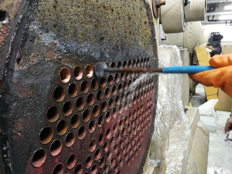
Mechanical Cleaning:
When fouling becomes significant, mechanical cleaning methods such as brushing, scraping, or high-pressure water jets can be employed to remove deposits. However, care must be taken to avoid damaging the heat exchanger surfaces.
Chemical Cleaning:
Chemical cleaning involves the use of specialized cleaning agents to dissolve or loosen fouling deposits. Acidic, alkaline, or chelating agents may be utilized depending on the type of fouling. Proper safety protocols and environmental considerations must be followed during chemical cleaning processes.
Advanced Technologies:
Innovative technologies like ultrasonic cleaning, pulsed power systems, or electromagnetic fields are being explored to enhance fouling control and removal efficiency.
Education and Training:
Promoting awareness and providing training to personnel regarding heat exchanger fouling, its causes, and preventive measures can contribute to better operational practices and early detection of fouling issues.
Conclusion
Heat exchanger fouling poses a significant challenge to the energy efficiency and reliability of industrial processes. Understanding the causes, consequences, and mitigation strategies is crucial for maintaining optimal heat exchanger performance and minimizing energy consumption. By implementing preventive measures, employing suitable cleaning techniques, and leveraging advanced technologies, industries can effectively combat fouling, reduce operational costs, and contribute to a more sustainable future. Regular monitoring, maintenance, and continuous improvement practices will play a vital role in maximizing the efficiency and longevity of heat exchangers, enabling industries to meet their energy efficiency goals while minimizing environmental impact.