Sheet metal is a versatile material used in a wide range of industries, including construction, automotive, manufacturing, and more. It is crucial to have a clear understanding of sheet metal thickness to ensure proper selection and usage. This is where a sheet metal gauge chart comes into play. In this article, we will explore the significance of a sheet metal gauge chart and provide insights into its interpretation for effective decision-making.
What is a Sheet Metal Gauge Chart?
A sheet metal gauge chart, also known as a sheet metal gauge table or sheet metal thickness chart, is a reference tool that provides a standardized measurement system for sheet metal thickness. It offers a comparison between different gauge numbers and their corresponding thicknesses in inches, millimeters, or other units of measurement. The chart typically lists a range of gauge numbers and their associated thickness values, allowing users to quickly determine the thickness of a specific sheet of metal.
Gauges are used to signify the sheet metal thickness. Using a sheet metal gauge chart, the user can easily convert the mentioned gauge into actual thicknesses in inches or mm. Steel thickness gauges can be used to verify the thickness. To give an example, For example, as per the gauge conversion chart table, 18 gauge steel is 0.0478 inches or 1.214 millimeters. The actual gauge number “18” does not hold any relevance to the actual measurements.
Understanding the Gauge Number System
The gauge number system used in sheet metal gauge charts is based on a numerical sequence, where lower gauge numbers indicate thicker sheets, while higher gauge numbers represent thinner sheets. However, the gauge system is not linear but follows a logarithmic scale. This means that the difference in thickness between two adjacent gauge numbers is not uniform but progressively decreases as the gauge number increases.
Note that, even though gauges are used to specify the thickness they are neither standard nor metric. The thickness values are independent of those measurement systems.
Standard Sheet Metal Gauge Chart
The most commonly used sheet metal gauge chart is based on the U.S. Standard Gauge (USG) system. This system assigns gauge numbers ranging from 1 to 36 to different sheet metal thicknesses. As per the USG system, gauge number 1 represents the thickest sheet metal, while gauge number 36 denotes the thinnest.
Interpreting the Sheet Metal Gauge Chart
When using a sheet metal gauge chart, it is essential to understand its interpretation. Here are a few key points to consider:
Gauge Number: Locate the gauge number on the chart that corresponds to the sheet metal you are working with. This will help you determine its thickness.
Thickness: Identify the thickness value associated with the chosen gauge number. The chart provides thickness measurements in inches, millimeters, or other units.
Conversion: If you are working with a gauge system that differs from the one on the chart, you may need to convert the gauge number to match the chart’s units. Conversion tables are available for this purpose.
Material Variations: Keep in mind that different types of sheet metal materials, such as steel, aluminum, or stainless steel, may have slight variations in thickness for a given gauge number. It’s advisable to consult material-specific charts or industry standards for precise measurements.
Sheet Metal Gauge Charts
Sheet metal gauge charts are not uniform with respect to different metals. This means that gauge 10 for Steel may not be same as the gauge 10 for Aluminum. Some of the sheet metal gauge charts for common materials are provided below:
Sheet Metal Gauge Chart for Mild Steel
Here’s a tabular format of a Sheet Metal Gauge Chart for Mild Steel:
Gauge Number
Thickness (inches)
Thickness (mm)
30
0.0120
0.30
28
0.0149
0.38
26
0.0179
0.45
24
0.0239
0.61
22
0.0299
0.76
20
0.0359
0.91
18
0.0478
1.21
16
0.0598
1.52
14
0.0747
1.90
12
0.1046
2.66
11
0.1196
3.04
10
0.1345
3.42
9
0.1495
3.80
8
0.1644
4.18
7
0.1793
4.55
6
0.1943
4.94
4
0.2242
5.70
2
0.2840
7.21
Table 1: Sheet Metal Gauge Chart for Mild Steel
Please note that these values represent a standard sheet metal gauge chart for mild steel, but there might be slight variations depending on specific manufacturing standards or regional practices. Always consult industry-specific guidelines or materials suppliers for precise measurements and specifications.
Sheet Metal Gauge Chart for Aluminum
The Sheet Metal Gauge Chart for Aluminum is provided in the following table:
Gauge Number
Thickness (inches)
Thickness (mm)
30
0.01003
0.26
28
0.01264
0.32
26
0.01594
0.41
24
0.02010
0.51
22
0.02535
0.64
20
0.03196
0.81
18
0.04030
1.02
16
0.05082
1.29
14
0.06408
1.63
12
0.08081
2.05
10
0.1019
2.59
8
0.1285
3.26
7
0.1443
3.66
Table 2: Aluminum Gauge Chart
Please note that these values represent a standard sheet metal gauge chart for aluminum, but there might be slight variations depending on specific manufacturing standards or regional practices.
Gauge Chart for other Metals
The gauge chart for Brass and Stainless Steel is provided in Table 3 below:
Brass Gauge Chart
Stainless Steel Gauge Chart
Gauge Number
Inches
MM
Gauge Number
Inches
MM
8
0.1285
3.264
8
0.1719
4.365
9
0.1144
2.906
9
0.1563
3.968
10
0.1019
2.588
10
0.1406
3.571
11
0.09074
2.305
11
0.125
3.175
12
0.08081
2.053
12
0.1094
2.778
14
0.06408
1.628
14
0.0781
1.984
16
0.05082
1.291
16
0.0625
1.587
18
0.0403
1.024
18
0.05
1.27
20
0.03196
0.812
20
0.0375
0.9525
22
0.02535
0.644
22
0.0313
0.7937
24
0.0201
0.511
24
0.025
0.635
26
0.01594
0.405
26
0.0188
0.476
28
0.01264
0.321
28
0.0156
0.396
30
0.01003
0.255
30
0.0125
0.3175
Table 3: Gauge Chart for Brass and Stainless Steel
Table 4 provides the Gauge chart for Copper and Galvanized Steel.
Galvanized Steel Gauge Chart
Copper Gauge Chart
Gauge Number
Inches
MM
Gauge Number
Inches
MM
8
0.1681
4.269
8
0.165
4.191
9
0.1532
3.891
9
0.148
3.759
10
0.1382
3.51
10
0.134
3.404
11
0.1233
3.1318
11
0.12
3.048
12
0.1084
2.753
12
0.109
2.769
14
0.0785
1.9939
14
0.083
2.108
16
0.0635
1.6129
16
0.065
1.651
18
0.0516
1.31
18
0.049
1.245
20
0.0396
1.005
20
0.035
0.889
22
0.0336
0.853
22
0.028
0.711
24
0.0276
0.701
24
0.022
0.559
26
0.0217
0.551
26
0.018
0.457
28
0.0187
0.474
28
0.014
0.356
30
0.0157
0.398
30
0.012
0.305
Table 4: Gauge Chart for Galvanized Steel and Copper
Practical Applications
A sheet metal gauge chart finds applications in various industries, including:
Sheet Metal Fabrication: Sheet metal workers, fabricators, and welders use the gauge chart to select the appropriate thickness for their projects, ensuring structural integrity and meeting design specifications.
Manufacturing: The manufacturing industry relies on accurate thickness measurements for sheet metal parts used in machinery, equipment, and consumer products.
Construction: Builders and contractors refer to the gauge chart to determine the appropriate sheet metal thickness for roofing, siding, ductwork, and other construction applications.
Automotive: In the automotive sector, the gauge chart aids in selecting sheet metal for body panels, frames, and other components, contributing to vehicle safety and performance.
Conclusion
A sheet metal gauge chart serves as a valuable tool for understanding the thickness of sheet metal materials. By providing a standardized measurement system, it allows users to quickly determine the thickness based on gauge numbers. Proper interpretation of the gauge chart is essential for selecting the appropriate sheet metal thickness for various applications. Whether in metal fabrication, manufacturing, construction, or automotive industries, referring to a sheet metal gauge chart helps ensure precision, quality, and compliance with industry standards.
As we have noted in my last article that all stainless steels do not show magnetic properties. Only certain grade of stainless steel material shows magnetic property and those can be magnetized. The composition of stainless steel decides if it can be magnetized. Any stainless steel with the presence of nickel in considerable amounts is difficult to magnetize, even though cold-rolling, stretching, and stressing the material can increase its magnetic potential. As series 200 and 400 stainless steel materials do not have nickel, they are naturally magnetic and hence, can be magnetized. In this detailed article, we will explore different methods to magnetize stainless steel, the factors influencing its magnetization, and the practical considerations involved in the process.
Methods to Magnetize Stainless Steel
Magnetizing stainless steel can be achieved through several methods, each with its advantages and considerations. It is important to note that the success and extent of magnetization may vary depending on the specific grade and composition of stainless steel.
Electromagnetic Induction:
Electromagnetic induction is a common method to magnetize stainless steel. It involves exposing the stainless steel to a strong magnetic field generated by an external electromagnet or a strong permanent magnet. By subjecting the stainless steel to this magnetic field, the alignment of the atomic dipoles can be temporarily altered, resulting in induced magnetization. However, this magnetization is typically weak and temporary unless the stainless steel is of a ferromagnetic grade or undergoes specific treatments.
Pulsed Magnetic Fields:
Applying a pulsed magnetic field to stainless steel can induce magnetization. Pulsed magnetic fields involve generating short bursts of high-intensity magnetic energy, which can realign the atomic dipoles in the stainless steel material and create a temporary magnetized state. This method is often used in specialized industrial processes and research applications.
Cold Working:
Cold working or deformation processes, such as bending, hammering, or rolling, can introduce strain into the stainless steel material. This strain can lead to the formation of localized magnetic regions, resulting in a weak magnetic response. However, the magnetization achieved through cold working is generally limited and may not be as pronounced or stable as in other methods.
Heat Treatment:
Heat treatment processes can alter the crystal structure of stainless steel, which can influence its magnetization. For example, subjecting certain austenitic stainless steel grades to low temperatures (around -196°C or -321°F) can induce a phase transformation called martensitic transformation, resulting in a ferromagnetic state. However, such transformations are specific to certain grades and must be carefully controlled to achieve the desired magnetic properties.
Factors Influencing Magnetization
The magnetization of stainless steel can be influenced by various factors:
Stainless Steel Grade:
Different stainless steel grades exhibit varying levels of magnetization. Austenitic stainless steel is generally non-magnetic, while ferritic and martensitic stainless steel grades can possess magnetic properties. Therefore, selecting the appropriate stainless steel grade is crucial for achieving the desired magnetization.
Crystal Structure:
The crystal structure of stainless steel plays a significant role in its magnetic behavior. Austenitic stainless steel, with its face-centered cubic structure, is non-magnetic. In contrast, ferritic and martensitic stainless steel, with their body-centered cubic and body-centered tetragonal structures, respectively, can exhibit magnetic properties.
Practical Considerations
When magnetizing stainless steel, certain practical considerations should be taken into account:
Limitations: Magnetizing stainless steel may result in weak or temporary magnetization. The extent and stability of magnetization depend on the specific stainless steel grade, treatment method, and processing conditions.
Expertise: Magnetizing stainless steel often requires specialized equipment, such as strong electromagnets or pulsed magnetic field generators. Consulting with experts or professionals experienced in magnetization processes is advisable to ensure optimal results and safety.
Material Integrity: Magnetization processes can potentially induce localized stresses or deformations in stainless steel. Care should be taken to minimize any adverse effects on the material’s structural integrity or performance.
Post-Magnetization Effects: After magnetization, the stainless steel may exhibit magnetic properties that can interfere with certain applications or equipment. Consideration should be given to the potential impact of magnetization on stainless steel’s intended use.
Conclusion
While stainless steel is primarily non-magnetic, there are methods available to magnetize it to varying degrees. Electromagnetic induction, pulsed magnetic fields, cold working, and heat treatment can influence the magnetization of stainless steel, although the extent and stability of magnetization can vary depending on factors such as stainless steel grade and crystal structure. It is important to consider the practical limitations, expertise required, and potential post-magnetization effects when attempting to magnetize stainless steel. Understanding these processes provides valuable insights for industries and applications where controlled magnetism in stainless steel may be advantageous or necessary.
Oxidation State of Nickel: Its Meaning, Significance, Parameters, and Applications
Nickel, a versatile and widely used transition metal, is known for its durability and excellent corrosion resistance. However, under certain conditions, nickel can undergo oxidation, leading to changes in its chemical and physical properties. In this article, we delve into the world of nickel oxidation, exploring its mechanisms, effects on other compounds, and applications.
What is Oxidation?
Oxidation is a chemical process that involves the loss of electrons by an atom, molecule, or ion. It occurs when a substance interacts with an oxidizing agent, which is typically a molecule or compound that readily accepts electrons. During oxidation, the oxidizing agent gains electrons while the substance being oxidized loses electrons.
Electrons are negatively charged particles that orbit around the nucleus of an atom. They play a crucial role in chemical reactions, as they determine the bonding and reactivity of atoms. When an atom loses electrons, it becomes positively charged because it now has more protons than electrons. This process is referred to as oxidation.
Oxidation reactions are commonly associated with the presence of oxygen, as oxygen is a highly effective oxidizing agent. However, oxidation can also occur without oxygen being directly involved. Other substances, such as halogens (e.g., chlorine, bromine), can act as oxidizing agents as well. With respect to Nickel oxidation, it is a measure of the added oxygen to the compound.
What is Nickel Oxidation?
Nickel oxidation refers to the process in which nickel atoms lose electrons and combine with oxygen atoms, resulting in the formation of various nickel oxide compounds. This transformative phenomenon alters the chemical behavior and physical properties of nickel.
Oxidation State of Nickel
The oxidation state of nickel is a measure of the number of electrons it gains or loses during oxidation. Nickel can exist in different oxidation states, ranging from -1 to +4 even though 0 (neutral) +2 (bivalent), and +3 (trivalent) are the most common oxidation states of nickel which exhibit distinctive chemical characteristics. In the +2 oxidation state, nickel loses two electrons (Example NiO), while in the +3 oxidation state, it loses three electrons (Example NiCl2). These oxidation states determine the charge on the nickel ion and profoundly influence its chemical reactivity.
Nickel Oxidation Number
The oxidation number of nickel is determined by the sum of the oxidation states of its constituent atoms. In the case of nickel, it is commonly represented as Ni2+ or Ni3+. These oxidation numbers indicate the charge on the nickel ion after losing or gaining electrons. For example, in nickel(II) oxide (NiO), nickel has an oxidation number of +2.
Nickel Oxidation Mechanism
The oxidation of nickel involves the transfer of electrons from the nickel atoms to oxygen. This process can occur through various mechanisms, such as direct reaction with oxygen, reaction with oxygen-containing compounds, or electrochemical oxidation. Factors like temperature, humidity, and the presence of impurities can influence the rate and extent of nickel oxidation.
One common mechanism is a direct reaction with oxygen, where nickel atoms react with oxygen molecules to form nickel oxide. Another mechanism involves the reaction of nickel with oxygen-containing compounds, such as water or carbon dioxide. Electrochemical oxidation, occurring during electrochemical reactions, is also significant, as in the case of nickel-plating processes.
Effects of Nickel Oxidation States on Other Compounds
The oxidation state of nickel plays a crucial role in its reactivity with other compounds. For instance, Nickel in the +2 oxidation state tends to form stable complexes with ligands, making it valuable in catalytic reactions and industrial processes. These complexes find applications in hydrogenation, polymerization, and organic synthesis. On the other hand, nickel in the +3 oxidation state exhibits strong oxidizing properties, enabling its participation in redox reactions and making it useful in various chemical processes.
Factors Affecting Nickel Oxidation States
Several factors can influence the oxidation states of nickel. These factors can either promote or hinder the oxidation of nickel and determine the stability and reactivity of different nickel oxidation states. Here are some key factors that affect nickel oxidation states:
Oxygen Availability:
The availability of oxygen is a significant factor in nickel oxidation. In the presence of oxygen, nickel can readily undergo oxidation reactions, resulting in the formation of nickel oxide compounds. Higher oxygen concentrations generally facilitate the oxidation of nickel.
Temperature:
Temperature plays a crucial role in nickel oxidation. Higher temperatures generally increase the rate of oxidation by providing the necessary energy for oxidation reactions to occur. Elevated temperatures can enhance the mobility of atoms and facilitate electron transfer, promoting the oxidation of nickel.
Humidity:
The presence of moisture or humidity can impact the oxidation of nickel. Moisture in the air can lead to the formation of a thin layer of water on the surface of nickel, which can act as a medium for oxidation reactions. Increased humidity levels can accelerate the oxidation process.
pH Level:
The pH level of the surrounding environment can affect nickel oxidation. In certain cases, acidic or alkaline conditions can promote the formation of specific nickel oxide compounds. The pH level influences the solubility and stability of different oxidation states of nickel, thereby affecting their propensity for oxidation.
Presence of Impurities:
The presence of impurities or other elements can significantly impact nickel oxidation. Some impurities can act as catalysts or promoters, facilitating the oxidation process. Conversely, certain elements may inhibit or retard the oxidation of nickel by forming protective surface layers or altering the electron transfer dynamics.
Surface Area and Reactivity:
The surface area of the nickel material can affect its oxidation. The higher surface area allows for more extensive interaction with the oxidizing agents, facilitating faster oxidation. Additionally, the reactivity of the nickel material, which can be influenced by its crystalline structure, grain size, and defects, can impact the ease of oxidation.
Time:
The duration of exposure to oxidizing conditions also affects nickel oxidation. Prolonged exposure to an oxidizing environment allows for more opportunities for oxidation reactions to occur, leading to a higher degree of oxidation.
Presence of Reducing Agents:
The presence of reducing agents, which have a tendency to donate electrons, can hinder nickel oxidation. Reducing agents can counteract the oxidizing properties of the environment and potentially stabilize the lower oxidation states of nickel.
It is essential to consider these factors when studying nickel oxidation as they can influence the extent, kinetics, and specific oxidation states observed in various conditions. By understanding these factors, researchers can better control and manipulate the oxidation process for specific applications or prevent undesired oxidation in certain contexts.
Applications of Nickel Oxidation
Nickel oxidation finds applications in various industries and fields. In the field of catalysis, nickel catalysts with different oxidation states are employed to facilitate chemical reactions. These catalysts find use in petroleum refining, hydrogenation processes, and organic synthesis. Nickel oxide coatings are utilized in batteries, fuel cells, and supercapacitors due to their high electrochemical activity. Additionally, nickel oxide compounds are essential components in the manufacturing of ceramic pigments, magnetic materials, and semiconductors, contributing to advancements in technology and materials science.
In conclusion, nickel oxidation is a fascinating process that significantly impacts the chemical and physical properties of this versatile metal. Understanding the oxidation mechanisms, effects on other compounds, and diverse applications of nickel oxidation provides valuable insights for scientists, engineers, and industries utilizing nickel in various processes. Continued research in this field will undoubtedly uncover new avenues for harnessing the potential of nickel oxidation in innovative technologies and materials.
What are Concrete Anchors? Their Applications, Materials, and Types
When it comes to construction projects, whether it’s a towering skyscraper, oil and gas facility, chemical and petrochemical complex, a residential building, or a simple home renovation, ensuring the strength and stability of the structure is paramount. One crucial element that contributes to the overall integrity and reliability of concrete structures is the use of anchors. Anchors play a vital role in connecting various components, reinforcing structural elements, and providing stability in concrete applications. In this article, we will delve into the world of anchors in concrete, exploring their types, functions, and the importance of proper installation techniques.
What are Concrete Anchors and How Do They Work?
Anchors, in the context of concrete construction, are devices or systems designed to attach or connect elements to a concrete surface. They are typically embedded into the concrete to provide a secure and lasting connection. Concrete anchors serve as a reliable attachment to secure objects in place. Anchors can distribute loads, resist forces, and prevent movement or failure of structural components. By creating a bond between the concrete and the anchor, they enhance the overall strength and stability of the structure.
A concrete anchor works by creating a secure connection between a concrete surface and another object or structural element. It prevents movement, rotation, or detachment of the attached component, enhancing the overall strength and stability of the structure. The working mechanism of a concrete anchor depends on its type, but the fundamental principle is to generate a bond that distributes and resists applied loads. The concrete anchors work in such a way that they provide a means for securing objects without damaging the concrete itself. They are found in various shapes and sizes, ensuring that for any project requirements, there is a suitable concrete anchor available. Fig. 1 below shows a typical example of concrete anchors.
Fig. 1: Typical Example showing Applications of Concrete Anchors
Types of Concrete Anchors
There are various types of concrete anchors used in the construction industry to cater to different needs. Broadly, the following concrete anchor types are widely used for industrial applications:
Sleeve Anchors
Wedge Anchors
Acoustical Wedge Anchors
Drop in Anchors
Double Expansion Shield Anchors
Lag Shield Expansion Anchors
Hammer Drive Pin Anchors
Split Drive Anchor
Threaded Rod Anchor
Strike Anchor
Plastic Toggle Anchors
Lag Anchor
Tapcon Concrete Anchor
Kaptoggle Hollow Wall Anchors
Machine Screw Angles Anchors
Masonry Screws
Sammys Screws
Toggle Wing Hollow Wall Anchors
Sleeve Anchors:
Sleeve anchors are versatile anchors suitable for a wide range of applications. They consist of a threaded bolt with a cone-shaped expander sleeve and a nut. When the anchor is inserted into a pre-drilled hole in the concrete, tightening the nut pulls the cone-shaped sleeve against the walls of the hole, causing it to expand and create a secure connection. Sleeve concrete anchors are easy to install and provide a durable and reliable solution.
Wedge Anchors:
Wedge anchors are designed for heavy-duty applications that require high load capacity. They consist of a threaded bolt with a wedge-shaped expansion clip at the bottom and a nut and washer. During installation, the anchor is inserted into a pre-drilled hole, and as the nut is tightened, the wedge-shaped clip expands, creating a secure grip between the anchor and the concrete. Due to their solid, lasting hold on even the most abrasive surfaces, Wedge anchors are extremely safe for use in permanent applications requiring incredible strength and long-lasting resistance.
Acoustical Wedge Anchors:
Acoustical wedge anchors are specifically designed for attaching acoustic panels and other similar materials to concrete surfaces. They feature a specially designed wedge-shaped clip that provides a strong grip and helps minimize vibration transmission.
Drop-in Anchors:
Drop-in anchors are internally threaded cylindrical anchors. They are placed into a pre-drilled hole in the concrete and then a threaded rod or bolt is inserted into the anchor. As the bolt is tightened, it expands the anchor and creates a secure connection.
Double Expansion Shield Anchors:
Double expansion shield anchors consist of a tubular-shaped shield with two expansion cones and a machine screw. When the anchor is inserted into a pre-drilled hole and the screw is tightened, the expansion cones expand radially, providing a secure hold within the concrete.
Lag Shield Expansion Anchors:
Lag shield expansion anchors are used to attach wood or metal components to concrete. They consist of a short, hollow cylindrical shield and a lag screw. The shield is inserted into a pre-drilled hole, and when the lag screw is driven into the shield, it expands and forms a tight grip within the concrete.
Hammer Drive Pin Anchors:
Hammer drive pin anchors, also known as hammer drive anchors or nail-in anchors, are simple and quick to install. They consist of a metal pin or nail with a nail head and a preassembled expansion sleeve. The pin is hammered into a pre-drilled hole, and as it goes in, the sleeve expands and secures the anchor in place.
Split Drive Anchor:
Split drive anchors feature a split cylindrical body with a wedge-shaped end and a lip. The anchor is inserted into a pre-drilled hole, and as a nail or screw is driven into the anchor, it causes the split body to expand, providing a secure hold in the concrete.
Threaded Rod Anchor:
Threaded rod anchors, as the name suggests, are used to attach threaded rods to concrete surfaces. They consist of a threaded sleeve or a nut with an internally threaded section that is embedded into the concrete. The threaded rod is then screwed into the anchor to create a secure connection.
Strike Anchor:
Strike anchors are heavy-duty anchors that provide excellent holding strength. They feature a cylindrical body with a cone-shaped end and a metal pin. The anchor is inserted into a pre-drilled hole, and a hammer or striking tool is used to drive the pin into the anchor, causing the cone-shaped end to expand and create a strong connection.
Plastic Toggle Anchor:
Plastic toggle anchors, also known as butterfly anchors, are used for light-duty applications. They consist of a plastic sleeve with two spring-loaded wings. When the anchor is inserted into a pre-drilled hole and the screw is tightened, the wings open behind the wall, providing stability and holding the anchor in place.
Lag Anchor:
Lag anchors are used for attaching wood or metal components to concrete surfaces. They consist of a lag screw threaded into a shield or an anchor body. The shield is inserted into a pre-drilled hole, and as the lag screw is tightened, it pulls the shield against the walls of the hole, creating a secure connection.
Tapcon Concrete Anchor:
Tapcon concrete anchors are specifically designed for fastening materials to concrete, brick, or block. They consist of a hardened steel screw with threads specially designed for concrete. These anchors are self-tapping, meaning they can be directly drilled into the material without the need for pre-drilling. As the screw is driven into the concrete, it creates threads and forms a strong bond.
Kaptoggle Hollow Wall Anchors:
Kaptoggle hollow wall anchors are primarily used for attaching objects to hollow walls, such as drywall. They consist of a spring-loaded toggle mechanism that expands behind the wall when the screw is inserted. The toggle provides stability and prevents the anchor from pulling out of the wall.
Machine Screw Angle Anchors:
Machine screw angle anchors, also known as Zamac anchors, are versatile anchors suitable for various materials, including concrete. They consist of a zinc alloy anchor body with a pre-assembled screw. The anchor is inserted into a pre-drilled hole, and as the screw is tightened, it expands the anchor, creating a secure hold.
Masonry Screws:
Masonry screws, often made of hardened steel, are designed for fastening materials to concrete, brick, or block. They feature a threaded shank and a hexagonal or Phillips’s head for easy installation using a screwdriver or drill. These screws are self-tapping and create their own threads as they are driven into the masonry.
Sammys Screws:
Sammy’s screws, also known as vertical anchoring systems, are used for attaching objects to concrete or steel surfaces. They consist of a threaded screw with a pointed end and a pre-assembled anchor body. The screw is driven through the object and into the anchor, which expands behind the surface, providing a secure connection.
Toggle Wing Hollow Wall Anchors:
Toggle wing hollow wall anchors are specifically designed for hollow walls, such as drywall. They consist of a spring-loaded toggle mechanism attached to a threaded bolt. When the anchor is inserted into the wall and the bolt is tightened, the wings on the toggle expand, gripping the backside of the wall and providing stability.
Each of these concrete anchor types offers unique features and advantages, allowing for a wide range of applications and ensuring secure and reliable connections between various materials and concrete surfaces. It is important to select the appropriate anchor type based on the specific requirements of the project to ensure optimal performance.
Materials for Concrete Anchors
Concrete anchors are available in a variety of materials, each chosen based on the specific application requirements and environmental conditions. The common materials used for concrete anchors include:
Steel: Steel is one of the most common materials for concrete anchors due to its strength, durability, and resistance to corrosion. Steel anchors can withstand heavy loads and provide long-lasting performance. They are often made of carbon steel, stainless steel, or coated steel to enhance corrosion resistance.
Zinc Alloy: Zinc alloy anchors, commonly known as Zamac anchors, are widely used for light to medium-duty applications. They offer good corrosion resistance and are cost-effective. Zinc alloy anchors are often used in drywall, masonry, and other non-structural applications.
Brass: Brass anchors are known for their corrosion resistance and aesthetic appeal. They are commonly used in applications where appearance is important, such as decorative fixtures or architectural elements. Brass anchors may be preferred in indoor or low-corrosion environments.
Nylon: Nylon anchors are lightweight, non-metallic anchors that offer excellent resistance to corrosion, chemicals, and electrical conductivity. They are commonly used in applications where insulation or non-conductive properties are required, such as electrical installations or areas with potential contact with water or chemicals.
Plastic: Plastic anchors, typically made of high-density polyethylene (HDPE) or other durable plastics, are lightweight and resistant to corrosion. They are commonly used for light-duty applications or in areas where electrical insulation is necessary. Plastic anchors are often used in drywall, lightweight fixtures, or low-load applications.
Epoxy: Epoxy anchors utilize an adhesive system made of epoxy resin. The epoxy material provides exceptional strength, chemical resistance, and adhesion to both the anchor and the concrete. Epoxy anchors are commonly used in high-load or critical applications where a strong bond is required, such as structural connections or heavy equipment installations.
It’s important to consider the material compatibility with the concrete and the specific environmental conditions in which the anchor will be installed. Proper material selection ensures the anchor’s longevity, reliability, and resistance to corrosion or degradation over time.
Importance of Proper Anchor Installation
Proper anchor installation is critical to ensure the effectiveness and reliability of the anchoring system. Here are a few key considerations for installation:
Load Capacity: Anchors must be selected based on the expected load requirements. It is essential to choose anchors that can withstand the anticipated loads to prevent failures or structural compromises.
Concrete Condition: The condition and quality of the concrete play a significant role in anchor performance. Factors such as compressive strength, age, moisture content, and the presence of cracks can affect the anchor’s ability to form a secure bond. It is crucial to assess the concrete condition and address any issues before anchor installation.
Correct Hole Preparation: The size and depth of the hole for anchor installation must be accurate. It is important to follow manufacturer guidelines and industry standards for hole diameter, depth, and cleanliness to ensure optimal anchoring performance.
Installation Techniques: Anchors should be installed using the appropriate tools and techniques. This includes ensuring proper torque or tension, avoiding overtightening, and following any specific installation procedures provided by the anchor manufacturer.
Applications of Anchors in Concrete
Anchors find extensive use in a wide range of concrete applications:
Structural Connections: Anchors play a crucial role in connecting structural components such as columns, beams, and walls, providing stability and load transfer.
Façade and Cladding Systems: Anchors are used to attach cladding systems to the concrete structure, ensuring their secure attachment and resistance to wind loads and other external forces.
Mechanical and Electrical Installations: Anchors are essential for securing mechanical equipment, HVAC systems, electrical panels, and piping to concrete surfaces.
Safety Systems: Anchors are utilized in the installation of safety equipment, such as guardrails, handrails, and lifeline systems, ensuring the protection of workers and preventing accidents.
Interior Fixtures: Anchors are commonly employed in the installation of fixtures like shelves, cabinets, and wall-mounted TVs, providing stability and preventing accidental tipping or falling.
Concrete Reinforcement: In certain cases, anchors are used to reinforce concrete structures by connecting additional steel elements or reinforcing bars, enhancing the overall strength and durability.
Maintenance and Inspection
Regular maintenance and inspection of anchors are crucial to ensure their continued effectiveness and reliability. Periodic assessments should be conducted to check for signs of corrosion, degradation, or loosening. If any issues are identified, appropriate actions such as anchor replacement or repair should be taken promptly to maintain the structural integrity of the concrete.
Conclusions
Anchors play an indispensable role in concrete construction, contributing to the strength, stability, and reliability of structures. Whether it’s for connecting structural components, attaching fixtures, or reinforcing concrete elements, the proper selection and installation of anchors are crucial for ensuring optimal performance. By understanding the different types of anchors, following recommended installation techniques, and conducting regular maintenance, builders, and engineers can create concrete structures that stand the test of time, providing safety and durability for years to come.
What is Process Piping? Its Definition, Materials, Codes, Applications, and Differences with Power Piping and Plumbing
Process piping plays a crucial role in various industries, enabling the safe and efficient transportation of fluids such as liquids, gases, and slurries. From chemical plants and refineries to pharmaceutical facilities and food processing units, process piping systems form the backbone of numerous industrial operations. This article provides a comprehensive overview of process piping, its components, materials, installation techniques, and maintenance practices, highlighting its significance in industrial fluid transportation.
What is Process Piping?
Process piping refers to a network of interconnected pipes, fittings, valves, and other components used to transport fluids within an industrial facility. These systems facilitate the movement of various substances, including water, chemicals, petroleum products, gases, steam, air, refrigerants, and many more. Process piping is designed to handle specific fluid types and meet stringent safety and performance standards.
In general, from an engineering perspective, a process piping system can be defined as a system of piping components designed following the guidelines mentioned in the ASME B31.3 code. Broadly, any piping system designed based on the ASME B31.3 code and used for transporting fluids under various temperatures, pressure, and environmental conditions is termed process piping. On the other hand, the piping system designed based on the ASME B31.1 code is termed power piping.
ASME B31.3 defines process piping as the piping used to carry substances in petroleum refineries; chemical, pharmaceutical, textile, paper, ore processing, semiconductor, and cryogenic plants; onshore and offshore petroleum and natural gas production facilities; food and beverage processing facilities; and related processing plants and terminals. So, as you can find process piping has a large number of applications in industrial facilities.
Components of Process Piping
Process Piping consists of a large variety of piping components. Some of the most widely used piping components for process piping are:
Pipes: The primary element of any process piping system, pipes are available in different materials such as carbon steel, stainless steel, copper, and plastic. The choice of material depends on factors such as fluid properties, temperature, pressure, and corrosion resistance requirements.
Fittings: Fittings are used to connect pipes, change direction, and control fluid flow. Common types include elbows, tees, reducers, and couplings. Like pipes, fittings are available in various materials and configurations to suit specific needs. More details about pipe fittings are provided here.
Valves: Valves regulate the flow and control the pressure of fluids in process piping systems. They can be manual or automated and are crucial for process control and safety. Common valve types include gate valves, globe valves, ball valves, and check valves.
Flanges: Flanges provide a means for connecting pipes and equipment, forming a secure joint. They are available in different standards, sizes, and pressure ratings, ensuring compatibility and leak-free connections.
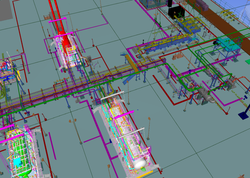
Note that various equipment like pressure vessel, pumps, compressors, turbines, heat exchangers, etc forms the complete system to operate the facility successfully but they are not part of process piping. They are used in process piping to complete the process piping system for performing the function of the system. A typical example of a process piping system is shown in the image below:
Typical Process Piping System
Materials for Process Piping
The choice of materials for process piping depends on factors such as fluid characteristics, temperature, pressure, and the environment. Common materials include:
Carbon Steel: Suitable for general-purpose applications, carbon steel offers good strength and affordability but may be prone to corrosion in certain environments.
Stainless Steel: Known for its excellent corrosion resistance, stainless steel is widely used in industries where hygiene and durability are critical, such as pharmaceuticals and food processing.
Alloy Steel: Alloy steel pipes are made by combining carbon steel with other elements, such as chromium, molybdenum, and nickel, to enhance their mechanical properties and corrosion resistance. In the chemical and petrochemical industries where applications involve high temperature and pressure, alloy steel materials are suitable.
Plastic: Materials like PVC, CPVC, and PTFE are used for non-corrosive applications, offering benefits such as chemical resistance, lightweight, and ease of installation.
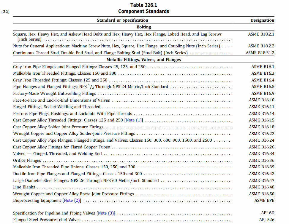
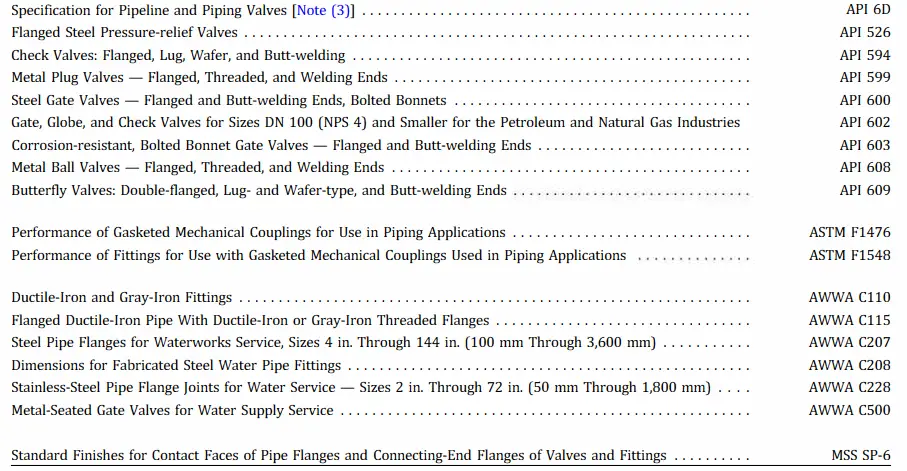
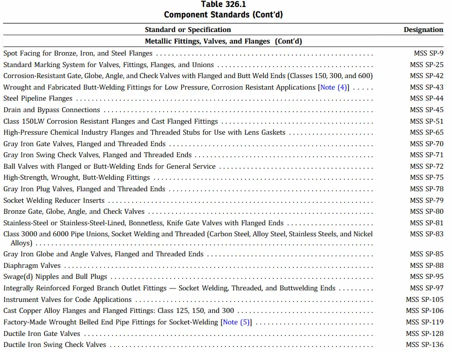
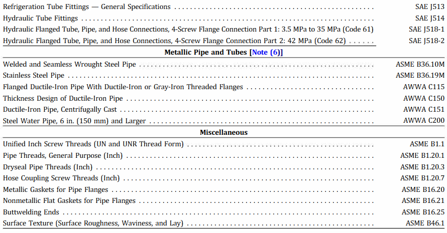
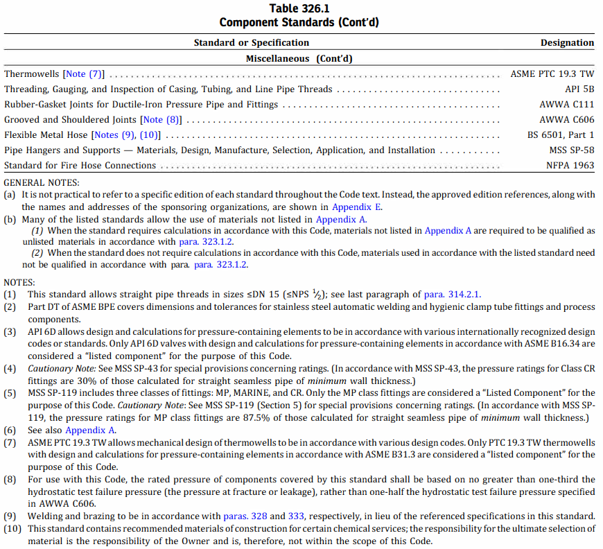
Even though ASME B31.3 is the main governing code for process piping, various other codes and standards are referred to design different components of the piping system. Table 326.1 of ASME B31.3 lists all such codes and standards. The same table is reproduced below for reference.
Installation Techniques and Standards
Process piping installation requires adherence to specific guidelines and industry standards to ensure safety and reliability. Proper installation techniques involve activities like pipe routing, cutting, threading, welding, and pressure testing. Standards such as ASME B31.3, ASME B31.1, and API 570 outline best practices for the design, fabrication, inspection, and testing of process piping systems.
Maintenance and Safety Considerations
Regular maintenance is crucial for the optimal performance and longevity of process piping systems. This includes inspection for leaks, corrosion, and mechanical damage, as well as cleaning and periodic replacement of components. Safety considerations involve implementing appropriate measures to prevent leaks, spills, and accidents, including the use of safety barriers, pressure relief devices, and emergency shutdown systems.
Process Piping vs Power Piping: Differences between Power Piping and Process Piping
The following table provides the key differences between Process piping and Power Piping.
Aspect
Process Piping
Power Piping
Purpose
Transporting fluids (liquids, gases, slurries)
Transporting steam, water, and other utilities
Fluid Type
Wide range of fluids (chemicals, petroleum, etc.)
Limited to steam, water, and other utilities
Pressure Rating
Lower pressure ratings
Higher pressure ratings
Material Selection
Wide range of materials (carbon steel, stainless steel, etc.)
Specific materials (carbon steel, alloy steel, etc.) for high-temperature and high-pressure applications
Code Standards
ASME B31.3 (Process Piping Code)
ASME B31.1 (Power Piping Code)
System Design
Emphasizes process control and fluid movement
Emphasizes energy transfer and power generation
Safety Considerations
Primarily focuses on fluid containment and chemical compatibility
Focuses on pressure control, thermal expansion, and high-temperature operation
Inspection
Inspected for leaks, corrosion, and mechanical damage
Inspected for pressure integrity and weld quality
Industry Applications
Chemical plants, refineries, pharmaceuticals, food processing, etc.
Power plants, utilities, therm
Table 1: Process Piping vs Power Piping; Main differences between Process Piping and Power Piping
It’s important to note that while there are distinct differences between process piping and power piping, there may be some overlap in certain applications, especially in facilities that have both process and power systems. Therefore, adherence to appropriate codes and standards is crucial to ensure the safe and efficient operation of piping systems in each specific context.
Differences between Process Piping and Plumbing: Plumbing vs Process Piping
Here’s a tabular format outlining the major differences between process piping and plumbing:
Aspect
Process Piping
Plumbing
Purpose
Transporting fluids (liquids, gases, slurries)
Supplying and distributing water, gas, and sewage
Fluid Type
Wide range of fluids (chemicals, petroleum, etc.)
Water, gas, sewage
Pressure Rating
Varies based on application and industry
Generally lower pressure ratings
Material Selection
Wide range of materials (carbon steel, stainless steel, etc.)
Commonly uses copper, PVC, PEX, and other plumbing-specific materials
Code Standards
ASME B31.3 (Process Piping Code) or specific industry standards
Local plumbing codes and regulations
System Design
Emphasizes process control and fluid movement
Emphasizes water supply, drainage, and fixture connections
Safety Considerations
Focuses on containment, chemical compatibility, and industrial safety measures
Focuses on health and sanitation, backflow prevention, and fixture functionality
Installation
Often involves larger pipe sizes and complex layouts
Involves smaller pipe sizes and simpler layouts
Fixtures and Equipment
Primarily focused on industrial equipment and machinery
Focuses on sinks, faucets, toilets, showers, and other household fixtures
Licensing and Certification
Requires specialized training and certifications for working in industrial settings
Requires specific plumbing licenses and certifications for compliance with local regulations
Table 2: Process Piping vs Plumbing
Conclusions
Process piping serves as the lifeline of industrial fluid transportation, enabling the efficient movement of liquids, gases, and slurries in diverse industries. Understanding the key components, materials, installation techniques, and maintenance practices associated with process piping is essential for ensuring the safe and reliable operation of industrial facilities. By selecting the appropriate materials, following industry standards, and conducting regular maintenance, companies can optimize the performance of their process piping systems while minimizing the risk of leaks, failures, and accidents.
With advancements in technology and the increasing complexity of industrial processes, process piping continues to evolve. New materials, such as composite pipes and advanced alloys, are being introduced to improve performance and reduce costs. Innovative installation techniques, such as prefabrication and modular construction, are gaining popularity for their efficiency and time-saving benefits.
Moreover, the integration of automation and control systems into process piping allows for real-time monitoring and remote control, enhancing safety and process efficiency. These advancements enable companies to improve their productivity, reduce downtime, and meet stringent regulatory requirements.
In conclusion, process piping is a critical component of industrial fluid transportation systems. It enables the safe and efficient movement of fluids within industrial facilities, serving as the backbone of various industries. By understanding the key components, materials, installation techniques, and maintenance practices associated with process piping, companies can ensure the reliable operation of their systems, optimize productivity, and enhance safety. Embracing technological advancements and adhering to industry standards will contribute to the continuous improvement of process piping systems, supporting the growth and success of industrial operations.
Heat Exchanger Fouling Factor: Its Significance and Calculation
Heat exchangers are vital components in numerous industrial applications, facilitating efficient heat transfer between two fluids. However, over time, the accumulation of unwanted deposits on heat exchanger surfaces, known as fouling, can significantly impact their performance. To evaluate and address the impact of fouling on heat exchanger efficiency, engineers and researchers rely on a crucial parameter called the fouling factor. In this article, we delve into the concept of the heat exchanger fouling factor, its significance, and the methods employed to calculate it accurately.
What is Heat Exchanger Fouling Factor?
The heat exchanger fouling factor represents the resistance posed by fouling deposits to the heat transfer process. It quantifies the decrease in heat transfer efficiency caused by fouling and is expressed as a thermal resistance value (m²·K/W). The higher the fouling factor, the more significant the impact of fouling on heat transfer performance.
Significance of the Heat Exchanger Fouling Factor
The fouling factor plays a crucial role in several aspects of heat exchanger design, operation, and maintenance:
Performance Evaluation:
By quantifying the extent of fouling, the fouling factor allows engineers to assess the degradation in heat exchanger performance. It helps identify the need for cleaning or maintenance activities and enables comparisons between different heat exchangers or operating conditions.
Energy Efficiency Analysis:
The fouling factor directly influences the energy consumption of a heat exchanger. Higher fouling factors indicate increased resistance to heat transfer, leading to higher energy requirements for maintaining desired process temperatures. By monitoring and controlling the fouling factor, energy efficiency can be optimized.
Equipment Sizing:
The fouling factor is considered during the design phase of a heat exchanger. It helps determine appropriate surface areas, fluid velocities, and other design parameters to account for the potential fouling impact. Proper sizing ensures the heat exchanger can handle anticipated fouling rates while maintaining desired performance.
Maintenance Planning:
By tracking the fouling factor over time, maintenance intervals and cleaning schedules can be established. Regular monitoring allows for proactive maintenance, minimizing the risk of equipment failure, optimizing performance, and reducing downtime.
Calculating the Heat Exchanger Fouling Factor
The fouling factor can be determined using various methods, depending on the type of fouling and available data:
LMTD (Log Mean Temperature Difference) Correction Method:
This method involves comparing the actual heat transfer area to the clean (initial) heat transfer area. By considering the reduction in effective area due to fouling, the fouling factor can be calculated.
ε-NTU (Effectiveness-Number of Transfer Units) Method:
Primarily used for analyzing shell-and-tube heat exchangers, this method utilizes the concept of heat exchanger effectiveness. The fouling factor is calculated by incorporating the fouling resistance into the overall heat transfer analysis.
Monitoring and Empirical Data:
In some cases, the fouling factor can be estimated based on empirical data obtained from similar systems or through continuous monitoring of fouling rates and performance degradation over time.
Factors Affecting the Heat Exchanger Fouling Factor
Several factors influence the magnitude of the fouling factor:
Fluid Composition:
The properties of the fluids being processed, including temperature, pH, chemical composition, and suspended solids, can significantly impact fouling rates.
Fluid Velocity:
Higher fluid velocities can help mitigate fouling by preventing deposition and promoting self-cleaning mechanisms. However, excessively high velocities can also cause erosion or increase pumping costs.
Operating Time:
Fouling tends to increase with longer operation times due to the gradual deposition of contaminants on heat exchanger surfaces. Therefore, the fouling factor may increase over time if proper maintenance and cleaning are not performed.
Temperature and Pressure:
Higher temperatures and pressures can accelerate fouling rates, especially for processes involving scaling or chemical reactions. Understanding the thermal and hydraulic conditions is crucial in assessing the fouling factor accurately.
Surface Roughness and Material Selection:
The roughness of heat exchanger surfaces can influence fouling tendencies. Smoother surfaces typically exhibit lower fouling rates. Additionally, material selection plays a vital role in minimizing fouling. Choosing materials resistant to corrosion and fouling can help mitigate the impact of deposits.
Fluid Treatment and Pretreatment:
Employing appropriate water treatment methods, such as filtration, softening, or the addition of chemical inhibitors, can reduce fouling tendencies and subsequently lower the fouling factor.
Heat Exchanger Fouling Factor Formula
Mathematically, the fouling factor for the heat exchanger (Rd) is represented as
Rd = 1 / Ud – 1 / U
where
Rd = fouling factor or unit thermal resistance of deposit (m2K/W)
Ud = overall heat transfer coefficient of heat exchanger after fouling (W/m2K)
U = overall heat transfer coefficient of clean heat exchanger (W/m2K)
Typical Heat Exchanger Fouling Factor Values
The following table provides some of the typical heat exchangers fouling factor values:
Substance
Fouling Factor (m2K/W)
Fuel Oil
0.0009
Alcohol Vapor
0.00009
Boiler Feed Water
0.0002
Steam
0.00009
Seawater
0.0002 to 0.00009
Industrial Air
0.0004
Refrigerating Liquid
0.0002
Quenching Oil
0.0007
Table 1: Heat Exchanger Fouling Factor Table
When performing heat transfer calculations, caution is exercised to select proper fouling factors as in some situations fouling resistances dominate the thermal design of the heat exchanger. General practice is to use a large fouling factor as a safety margin to cover uncertainties in fluid properties. However, a large fouling factor may result in an oversized heat exchanger than required. Many experience-based tabulations of heat exchanger fouling factors are available to get typical fouling factors such as TEMA Table RGP-T-2.4.
Conclusions
The heat exchanger fouling factor serves as a key parameter in evaluating the impact of fouling on heat transfer efficiency. By understanding its significance and employing accurate calculation methods, engineers can make informed decisions regarding heat exchanger design, operation, and maintenance. Regular monitoring of the fouling factor, along with appropriate cleaning and maintenance practices, enables optimization of energy efficiency, reduction of operational costs, and avoidance of equipment failures. By addressing heat exchanger fouling issues proactively and implementing effective strategies, industries can ensure optimal heat exchanger performance, prolong equipment lifespan, and contribute to sustainable and cost-effective operations.