In oil and gas piping applications, a bypass valve is a type of valve used to divert or redirect the flow of fluids within a system. It is designed to create an alternate flow path, allowing the fluid to bypass certain components or sections of the piping system. Bypass valves are mounted in bypass loops or bypass lines.
Purpose of Bypass Valves
The primary purpose of a bypass valve is to provide operational flexibility, maintenance convenience, and system safety. Here are a few common applications and benefits of bypass valves in oil and gas piping:
Maintenance and Repair:
During maintenance or repair activities, certain equipment or sections of the piping system may need to be isolated for inspection, replacement, or repair. By installing a bypass valve, the fluid flow can be redirected around the isolated area, ensuring uninterrupted operation of the rest of the system.
Pressure Regulation:
Bypass valves can be utilized to regulate pressure within a piping system. By adjusting the position of the bypass valve, operators can divert a portion of the flow to either increase or decrease pressure in specific areas, ensuring optimal operation of downstream equipment.
System Start-Up and Shutdown:
During system start-up or shutdown, bypass valves can be employed to gradually increase or decrease flow rates, preventing sudden pressure surges or shocks that could damage sensitive equipment.
System Testing:
Bypass valves facilitate system testing by allowing fluid flow to be redirected to a test loop or auxiliary equipment for evaluation without affecting the primary operation of the system.
Valves Suitable as Bypass Valves
Bypass valves come in various designs, including gate valves, globe valves, ball valves, or butterfly valves, depending on the specific requirements and characteristics of the piping system. They are typically installed in parallel or in bypass lines adjacent to the primary flow path and can be manually operated or automated, depending on the system’s complexity and control requirements.
The choice of valve depends on factors such as fluid characteristics, system requirements, pressure ratings, and operating conditions. Here are some commonly used valve types for bypass applications:
Ball Valves:
Ball valves are versatile and widely used in bypass applications. They offer low resistance to flow, quick operation, and tight shut-off capabilities. They are suitable for both on/off and throttling operations. Ball valves can be designed with a full port or reduced port, depending on the flow requirements.
Gate Valves:
Gate valves are often employed as bypass valves due to their ability to provide a straight-through flow path. They offer low-pressure drop and good shut-off capabilities. Gate valves are commonly used in isolation applications, but they can also be used as bypass valves when properly sized and installed.
Globe Valves:
Globe valves are suitable for throttling and regulating flow in bypass applications. They provide precise flow control and have good shut-off characteristics. Globe valves are often preferred when fine adjustments or flow modulation are required.
Butterfly Valves:
Butterfly valves are compact and lightweight, making them suitable for space-limited applications. They offer quick operation and provide low-pressure drops. Butterfly valves are commonly used for larger pipe sizes and can be effective as bypass valves when designed appropriately.
Check Valves:
In some cases, check valves can be utilized as bypass valves to allow flow in one direction and prevent backflow. Check valves are typically used in situations where flow reversal needs to be avoided, such as in pump bypass applications.
Working of a Bypass Valve
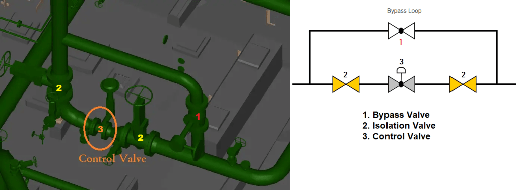
To understand the working of a bypass valve let’s take an example of a control valve station as shown in Fig. 1 below:
Fig. 1: Working of a Bypass Valve
During normal operation, the isolation valves are kept open while the bypass valve is closed. So flow is transferred through the isolation and control valves and there is no flow through the bypass valve. During maintenance, if the control valve needs to be replaced, it has to be taken out of service. So, the maintenance professional will gradually open the bypass valve while closing the control valve in case of manual operation otherwise close one of the isolation valves.
So, the flow will gradually be transferred from the main line to the bypass line. An instrument usually indicates the flow or pressure of the line that the operator can easily observe. Once the flow is fully transferred to the bypass valve, both isolation valves are closed and the control valve can be vented or drained using the drain or vents installed in the line. The control valve can now be taken for maintenance or repair. So now the plant will operate normally and the flow will move through the bypass valve.
Applications of Bypass Valves
Bypass valves find applications in various industries and systems where redirecting or regulating the flow of fluids is necessary. Some common applications of bypass valves include:
Oil and Gas Pipelines:
Bypass valves are used in oil and gas pipelines for maintenance and repair activities. They allow the flow to be redirected, bypassing sections that require maintenance or isolation, ensuring uninterrupted operation of the rest of the pipeline.
Water Treatment Plants:
Bypass valves are employed in water treatment plants to divert the flow during maintenance, repair, or replacement of filtration systems, pumps, or other equipment. They ensure continuous water supply while the affected components are serviced.
Cooling Systems:
Bypass valves are used in cooling systems, such as HVAC (Heating, Ventilation, and Air Conditioning) systems, to regulate and control the flow of coolant or chilled water. They can redirect the flow to maintain optimal cooling performance, especially during maintenance or when specific areas require additional cooling.
Process Industries:
Bypass valves find applications in various process industries, such as chemical plants, refineries, and power plants. They are used to isolate equipment, redirect flows for testing or sampling purposes, and control pressure or flow rates in different parts of the system.
Steam Systems:
Bypass valves are utilized in steam systems to control pressure, divert steam flows, or bypass equipment during maintenance or shutdown. They allow for safe and efficient operation while specific components are serviced.
Hydraulic Systems:
Bypass valves are commonly employed in hydraulic systems to regulate pressure and flow rates. They can be used to bypass or isolate hydraulic components or control the operation of actuators and cylinders.
Fire Protection Systems:
Bypass valves play a crucial role in fire protection systems, such as sprinkler systems. They allow for testing, maintenance, and repair of the fire protection equipment without interrupting the overall system’s functionality.
Compressed Air Systems:
Bypass valves are used in compressed air systems to divert or isolate certain sections for maintenance, repair, or pressure regulation. They ensure continuous airflow while specific components or sections are serviced.
What are HFO Refrigerants? Their Benefits and Applications
Refrigerants play a crucial role in keeping our homes, businesses, and industries cool. However, the commonly used refrigerants, such as hydrochlorofluorocarbons (HCFCs) and hydrofluorocarbons (HFCs), have been found to contribute to global warming and ozone depletion. In response to these environmental concerns, a new generation of refrigerants known as Hydrofluoroolefins (HFOs) has emerged. In this article, we will delve into the world of HFO refrigerants, exploring their environmental benefits, properties, and their potential to shape a sustainable future for cooling technologies.
What are HFO Refrigerants?
HFO refrigerants are part of a family of organic compounds that contain hydrogen, fluorine, and carbon atoms. They are designed to provide effective cooling properties while minimizing their impact on the environment. HFOs are characterized by their low global warming potential (GWP), which measures the potential for trapping heat in the atmosphere compared to carbon dioxide (CO2). HFOs have GWPs that are significantly lower than traditional refrigerants, making them a greener alternative.
Environmental Benefits of HFO Refrigerants
Ozone Depletion Potential:
HFO refrigerants have an ozone depletion potential (ODP) of zero, meaning they do not contribute to the depletion of the Earth’s protective ozone layer. This makes them an ideal replacement for older refrigerants like HCFCs and HFCs, which have higher ODP values.
Low Global Warming Potential:
HFO refrigerants boast remarkably low GWPs, often less than 1, compared to HFCs that can have GWPs in the thousands. This characteristic allows HFOs to significantly reduce greenhouse gas emissions, mitigating their impact on climate change.
Regulatory Compliance:
With increasing environmental regulations, HFO refrigerants are gaining popularity as they align with global efforts to phase out high-GWP refrigerants. Governments and international organizations have recognized the importance of transitioning to eco-friendly alternatives, and HFOs are playing a vital role in meeting these compliance requirements.
Properties and Performance of HFO Refrigerants
Energy Efficiency:
HFO refrigerants have excellent heat transfer properties, allowing for efficient cooling and energy savings. Their thermodynamic characteristics make them suitable for various cooling applications, including air conditioning, refrigeration, and heat pump systems.
Compatibility:
HFO refrigerants are designed to be compatible with existing refrigeration equipment, reducing the need for extensive modifications during retrofitting or system upgrades. This compatibility facilitates a smooth transition to HFO refrigerants without significant infrastructure changes.
Safety Considerations:
HFO refrigerants are generally considered safe for use, with low toxicity and flammability levels compared to some older refrigerants. However, as with any refrigerant, proper handling, storage, and system design considerations should be followed to ensure safe operation.
Technological Advancements:
HFO refrigerants have inspired innovation in cooling technologies. Manufacturers have developed advanced compressors, heat exchangers, and system designs optimized for HFOs, resulting in improved overall system performance and energy efficiency.
List of HFO Refrigerants
Here is a list of some commonly used HFO refrigerants:
R1234yf: This HFO refrigerant is widely used in automotive air conditioning systems as a replacement for the high-GWP HFC-134a. It has a very low GWP of less than 1 and is considered environmentally friendly.
R1234ze: Another HFO refrigerant, R1234ze, is used in various applications, including chillers, heat pumps, and air conditioning systems. It has a GWP of less than 1 and offers good energy efficiency.
R1233zd: This HFO refrigerant is suitable for use in centrifugal chillers, heat pumps, and industrial refrigeration systems. It has a very low GWP and exhibits excellent thermodynamic properties.
R1234ze(E): Similar to R1234ze, R1234ze(E) is used in chillers, air conditioning, and heat pump applications. It has a GWP of less than 1 and is considered a non-flammable alternative.
R1234yf/DME (R444B): This blend of HFO refrigerant and dimethyl ether (DME) offers a low GWP alternative for various cooling applications. It is commonly used in air conditioning systems and shows promise as an environmentally friendly option.
R1234zd(E): R1234zd(E) is primarily used in low-pressure centrifugal chillers and offers an ultra-low GWP. It provides excellent energy efficiency and heat transfer properties.
Applications of HFO Refrigerants
HFOs (Hydrofluoroolefins) have found various applications across different industries and sectors due to their environmental friendliness and energy efficiency. Here are some notable applications of HFOs:
Air Conditioning and Heat Pump Systems:
HFOs are commonly used as refrigerants in air conditioning and heat pump systems. They provide efficient cooling and heating capabilities while minimizing environmental impact. HFOs enable the development of energy-efficient systems that meet regulatory requirements and contribute to sustainable cooling solutions.
Commercial and Industrial Refrigeration:
HFOs are utilized in commercial and industrial refrigeration systems, including supermarkets, cold storage facilities, food processing plants, and pharmaceutical industries. They offer reliable and efficient cooling for preserving perishable goods while reducing the carbon footprint.
Automotive Air Conditioning:
HFO refrigerants, particularly R1234yf, have been adopted as alternatives to high-GWP HFC-134a in automotive air conditioning systems. HFOs enable car manufacturers to meet environmental regulations and reduce greenhouse gas emissions associated with vehicle air conditioning.
Domestic Refrigeration:
HFOs are being increasingly used in domestic refrigeration, such as refrigerators and freezers. By replacing older refrigerants with HFOs, manufacturers can offer energy-efficient appliances that minimize the environmental impact throughout their lifecycle.
Chillers:
HFOs find applications in commercial and industrial chillers used for air conditioning in large buildings, hotels, hospitals, and data centers. HFO refrigerants provide effective cooling performance while reducing the overall environmental impact of the cooling system.
Heat Recovery Systems:
HFOs are used in heat recovery systems, where waste heat from industrial processes or HVAC systems is captured and utilized for heating purposes. HFOs enable efficient heat transfer, maximizing the energy recovery potential.
Transport Refrigeration:
HFO refrigerants are suitable for use in transport refrigeration units, such as refrigerated trucks and shipping containers. By using HFOs, the cooling systems in these vehicles can provide efficient temperature control while minimizing the impact on the environment.
Water Heating Heat Pumps:
HFOs are employed in water-heating heat pumps, which use heat from the air, ground, or water to provide hot water for domestic or commercial use. HFOs in these systems ensure energy-efficient operation and reduced greenhouse gas emissions compared to conventional heating methods.
It’s important to note that the specific choice and application of HFO refrigerants may depend on factors such as system design, performance requirements, safety considerations, and regional regulations. Ongoing research and development in the field of HFOs continue to expand their applications and promote more sustainable cooling solutions across industries.
Conclusion
HFO refrigerants represent a significant leap forward in the quest for sustainable cooling solutions. With their low environmental impact, high energy efficiency, and regulatory compliance, HFOs are poised to become the future of refrigerants. As industries and consumers alike increasingly prioritize environmental responsibility, the adoption of HFO refrigerants in cooling systems will contribute to mitigating climate change and protecting the ozone layer. By embracing these environmentally friendly alternatives, we can pave the way for a cooler future that is both efficient and sustainable.
What is a Heat Pump? Its Components, Working, Types, Advantages, and Disadvantages
In our quest for sustainable living and reducing our carbon footprint, heat pumps have emerged as a remarkable solution. These versatile devices have revolutionized the way we heat and cool our homes, offering efficient and eco-friendly alternatives to traditional heating and cooling systems. In this article, we will dive into the world of heat pumps, exploring their working principles, benefits, and their potential to transform the way we use energy in our daily lives.
What is a Heat Pump?
A heat pump is a mechanical device that transfers heat from one location to another using a small amount of energy. Unlike conventional heating and cooling systems, which generate heat or cool air directly, heat pumps simply move heat from one place to another. By extracting heat from the air, ground, or water, heat pumps can provide both heating and cooling functions, making them highly versatile and energy-efficient.
Components of a Heat Pump
A heat pump consists of several key components that work together to facilitate the transfer of heat. The main components of a typical heat pump system include:
Evaporator: The evaporator is responsible for absorbing heat from the source medium, such as air, water, or the ground. It contains a coil through which a refrigerant passes, evaporating as it absorbs heat from the surrounding medium.
Compressor: The compressor plays a vital role in the heat pump cycle. It receives the low-pressure, low-temperature vaporized refrigerant from the evaporator and compresses it, increasing both its temperature and pressure. This process raises the energy level of the refrigerant, preparing it for the next stage of heat transfer.
Condenser: The condenser facilitates the release of heat from the high-pressure, high-temperature refrigerant. It consists of a coil or series of tubes that allow the refrigerant to give off heat to the desired space or environment. As the refrigerant condenses back into a liquid state, it transfers the accumulated heat to the surroundings.
Expansion Valve: The expansion valve acts as a metering device and pressure regulator in the heat pump system. It regulates the flow of refrigerant from the high-pressure side (condenser) to the low-pressure side (evaporator). By creating a pressure drop, the expansion valve enables the refrigerant to expand, cool down, and prepare for the evaporation process in the evaporator.
Reversing Valve: The reversing valve of the heat pump helps to reverse the flow of refrigerant. It allows the heat pump system to operate in the opposite direction and switch between heating and cooling.
Refrigerant: The refrigerant is a specially formulated fluid with excellent heat transfer properties. It undergoes phase changes (evaporation and condensation) during the heat pump cycle, absorbing and releasing heat in the process. Common refrigerants used in heat pumps include environmentally friendly options like R-410A and R-32.
Air Handler or Fan: In air-source heat pumps, an air handler or fan is used to circulate the air across the evaporator and condenser coils. The air handler helps distribute the heated or cooled air throughout the building or space being conditioned.
Additional components may also be present in more complex heat pump systems, depending on the specific configuration and features. These can include filters, sensors, control panels, and auxiliary heating elements for supplemental heating when required.
Working Principles of Heat Pump
Heat pumps work based on the principles of thermodynamics, utilizing the properties of refrigerants to transfer heat. The primary components of a heat pump system include the evaporator, compressor, condenser, and expansion valve. Here’s a simplified overview of how a heat pump works:
Evaporation: The refrigerant evaporates at a low temperature, absorbing heat from the surrounding air, ground, or water.
Compression: The compressor raises the pressure and temperature of the refrigerant, further increasing its heat content.
Condensation: The hot refrigerant passes through the condenser, releasing heat to the indoor or outdoor environment.
Expansion: The refrigerant, now in a cool, low-pressure state, returns to the evaporator to restart the cycle.
Heating and Cooling Applications
One of the most significant advantages of heat pumps is their ability to provide both heating and cooling. During colder months, heat pumps extract heat from the outside environment and transfer it indoors for heating purposes. Conversely, during warmer months, the cycle reverses, as heat pumps remove heat from the indoor space and release it outdoors, effectively cooling the area.
How does a Heat Pump Cool and Heat?
A heat pump can both cool and heat by utilizing the same basic refrigeration cycle, but with a reversing valve that allows for the reversal of the refrigerant flow. Here’s a breakdown of how a heat pump operates for both cooling and heating modes:
Heat Pump Working for Cooling Mode:
Evaporator: In cooling mode, the heat pump absorbs heat from the indoor space. The refrigerant flows through the evaporator coil, which is located inside the building. As warm indoor air passes over the coil, the refrigerant evaporates, absorbing the heat from the air.
Compressor: The low-pressure, low-temperature vaporized refrigerant is then compressed by the compressor. This compression increases the temperature and pressure of the refrigerant, raising its energy level.
Condenser: The hot, high-pressure refrigerant now moves to the condenser coil, located outside the building. As the outdoor air passes over the condenser coil, the refrigerant releases heat to the outdoor environment, cooling down and condensing into a liquid state.
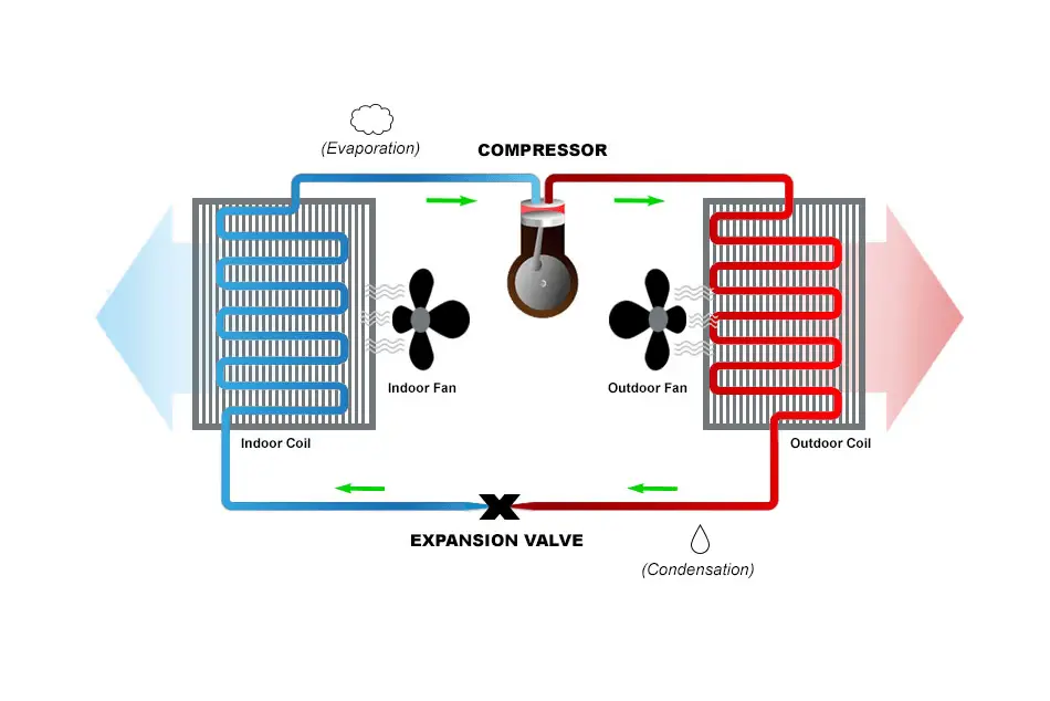
Expansion Valve: After the refrigerant leaves the condenser, it passes through the expansion valve, where it undergoes a pressure drop. This drop in pressure causes the refrigerant to cool down further, preparing it for the evaporator coil and restarting the cycle. The schematic in Fig. 1 (Image Courtesy: https://www.carrier.com/residential/en/us/products/heat-pumps/what-is-a-heat-pump-how-does-it-work/ ) clearly explains the working of heat pumps.
Fig. 1: Working of Heat Pumps
Heat Pump Working in Heating Mode:
Reversing Valve: To switch to heating mode, the reversing valve in the heat pump is activated, allowing the refrigerant flow to reverse its direction.
Evaporator and Condenser: In heating mode, the outdoor coil becomes the evaporator, absorbing heat from the outside air. The indoor coil, now acting as the condenser, releases heat to the indoor space.
Compressor and Expansion Valve: The refrigerant flows through the compressor, which raises its temperature and pressure, and then to the expansion valve, where it undergoes a pressure drop and cools down.
Heat Distribution: The heated refrigerant in the indoor coil transfers its heat to the air circulating through the air handler or fan. The warm air is then distributed throughout the building, providing heating.
By reversing the flow of the refrigerant and utilizing the heat transfer process, a heat pump can alternate between cooling and heating modes, making it a versatile system for maintaining desired indoor temperatures throughout the year. This ability to provide both heating and cooling makes heat pumps an efficient and cost-effective solution for temperature control in residential and commercial settings.
Types of Heat Pumps
Air-Source Heat Pumps:
These heat pumps extract heat from the outdoor air and transfer it indoors during winter. In summer, the cycle reverses, expelling heat from indoors to the outside. They are easy to install, cost-effective, and suitable for moderate climates.
Ground-Source Heat Pumps (Geothermal):
These heat pumps harness the relatively stable temperature of the ground. They circulate fluid through underground pipes, extracting heat in winter and dissipating heat in summer. Geothermal heat pumps are highly efficient but require more installation effort and initial investment.
Absorption Heat Pumps:
Absorption heat pumps are a type of heat pump that uses a heat source to drive the refrigeration cycle instead of an electric compressor. They operate based on the principle of absorption refrigeration and can provide both heating and cooling functions.
Benefits of Heat Pumps
Energy Efficiency:
Heat pumps are significantly more energy-efficient than traditional heating and cooling systems since they move heat rather than generate it. They can achieve energy savings of up to 50% compared to conventional methods.
Reduced Carbon Footprint:
Heat pumps operate on electricity and can utilize renewable energy sources, resulting in a significant reduction in greenhouse gas emissions compared to fossil fuel-based systems.
Cost Savings:
Although the upfront cost of installing a heat pump may be higher, the long-term energy savings and potential government incentives can offset the initial investment, leading to considerable cost savings over time.
Versatility and Convenience:
Heat pumps offer the flexibility of providing both heating and cooling functions, eliminating the need for separate systems. They can also be integrated with other technologies, such as solar panels, further enhancing their energy efficiency.
What is a Water Heating Heat Pump?
A water heating heat pump, also known as a heat pump water heater (HPWH), is a specific type of heat pump designed to efficiently heat water for domestic use. It operates on the same principles as a traditional heat pump but focuses on providing hot water instead of heating or cooling indoor spaces. A water heating heat pump extracts heat from the surrounding air, ground, or water and transfers it to the water, resulting in an energy-efficient and cost-effective method of water heating.
It’s important to note that the performance of a water heating heat pump can vary depending on factors such as ambient temperature, humidity, and the location of the unit. However, when properly sized and installed in suitable conditions, water heating heat pumps can offer an efficient and reliable solution for meeting hot water needs while reducing energy consumption and costs.
What is Principle of Heat Pump?
The principle of a heat pump is based on transferring heat rather than generating it, utilizing the thermodynamic refrigeration cycle. It operates by moving heat from one location to another: in cooling mode, it extracts heat from the indoor air and releases it outside, while in heating mode, it absorbs heat from the outside air, ground, or water and transfers it indoors. This process involves a refrigerant that circulates through the system, undergoing compression to increase its temperature and pressure, then releasing or absorbing heat as it passes through coils. The refrigerant is then expanded, lowering its temperature and pressure, and the cycle repeats. By reversing the refrigerant flow, a heat pump can efficiently provide both heating and cooling, often with greater energy efficiency compared to conventional systems
What is a Mini Split Heat Pump?
A mini-split heat pump, also known as a ductless heat pump or ductless mini-split system, is a type of heat pump that provides both heating and cooling functions without the need for ductwork. It consists of two main components: an outdoor unit (condenser/compressor) and one or more indoor units (evaporator/fan coil). The indoor and outdoor units are connected by refrigerant lines, electrical wiring, and a conduit, allowing for the transfer of heat or cooling.
Here are some key features and characteristics of a mini-split heat pump:
Ductless Design: Unlike traditional HVAC systems that rely on ductwork to distribute conditioned air, mini-split heat pumps are ductless. This makes them ideal for retrofitting older homes or buildings without existing ductwork or for areas where adding ducts would be impractical.
Zone Heating and Cooling: Mini-split systems allow for zoned temperature control, enabling different rooms or areas to be heated or cooled independently. Each indoor unit is installed in its designated space and can be controlled individually, providing personalized comfort and energy efficiency.
Installation Flexibility: Mini-split heat pumps offer flexible installation options. The indoor units can be mounted on walls, suspended from ceilings, or recessed into the ceiling, depending on the specific requirements and aesthetics of the space. The outdoor unit is typically placed outside the building.
Energy Efficiency: Mini-split heat pumps are known for their energy efficiency. They utilize inverter-driven compressors that adjust their speed according to the heating or cooling demand, resulting in precise temperature control and reduced energy consumption.
Heat Pump Operation: Mini-split systems work based on the same principles as other heat pumps. In heating mode, the outdoor unit extracts heat from the outside air and transfers it to the indoor unit(s) to provide warmth. In cooling mode, the process is reversed, with the heat pump absorbing heat from indoor air and releasing it outdoors.
Remote Control and Smart Features: Many mini-split heat pumps come with remote control or smartphone apps, allowing for easy operation and temperature adjustments. Some models also offer advanced features like programmable timers, sleep modes, and Wi-Fi connectivity for convenient control and energy management.
Quiet Operation: Mini-split heat pumps are designed to operate quietly, providing comfortable and noise-free environments.
Mini-split heat pumps are widely used in residential homes, commercial spaces, and even multi-zone applications like hotels or office buildings. Their compact size, installation flexibility, energy efficiency, and zoning capabilities make them a popular choice for efficient heating and cooling in a wide range of settings.
Advantages and Disadvantages of Heat Pumps
The major advantages and disadvantages of heat pumps are provided in table-1 below:
Advantages
Disadvantages
High Energy Efficiency
Higher upfront cost compared to some systems
Provides both heating and cooling functions
Can provide hot water with a water-heating heat pump
Lower greenhouse gas emissions
Performance affected by extreme temperatures
Can be powered by renewable energy sources
Initial installation complexity in some cases
Energy savings and reduced utility bills
Regular maintenance and servicing required
Versatility in integration with other systems
May require additional space for an outdoor unit
Can provide hot water with a water heating heat pump
Some types may produce noise during operation
Table 1: Advantages and Disadvantages of Heat Pumps
Heat Pump vs Air Conditioner
The major differences between heat pumps and air conditioners are provided in Table 2 below:
Parameter
Heat Pump
Air Conditioner
Function
Provides both heating and cooling functions
Provides cooling only
Operation
Reversible, can switch between heating and cooling modes
Operates in cooling mode only
Heating Source
Extracts heat from air, ground, or water
Does not provide heating
Cooling Source
Expels heat to the outside environment
Expels heat to the outside environment
Energy Efficiency
Highly energy efficient, can provide energy savings
Energy efficiency varies, may have lower efficiency
Seasonal Use
Suitable for year-round use in different climates
Primarily used during hot seasons
Installation
Can be more complex and may require additional components for heating functionality
Simpler installation
Energy Source
Can utilize renewable energy sources like solar power
Requires electricity
Cost
The initial investment may be higher, but long-term energy savings can offset costs
Lower initial cost
Environmental Impact
Lower greenhouse gas emissions, reduced carbon footprint
Higher energy consumption, increased environmental impact
Versatility
Can be integrated with other systems like solar panels for enhanced efficiency
Limited to cooling applications
Table 2: Differences between Heat Pump and Air Conditioner
It’s worth noting that there are different types of air conditioners, such as window units, split systems, and central air conditioning, which may have variations in their features and capabilities. The table above provides a general comparison between heat pumps and air conditioners, focusing on the key differences.
Is a Heat Pump better than Air Conditioner?
A heat pump can be more versatile than a traditional AC because it functions as both a heating and cooling system, making it a year-round solution. It works by transferring heat rather than generating it, which can be more energy-efficient and cost-effective, especially in moderate climates. In contrast, a traditional AC is designed solely for cooling and may be more suitable for regions with intense heat and less need for heating. While heat pumps can be more efficient overall, their performance can decrease in very cold temperatures, potentially requiring a supplementary heating source. Thus, the choice between a heat pump and an AC largely hinges on your local climate, energy efficiency goals, and whether you need a combined heating and cooling solution.
Differences between a Chiller and a Heat Pump
The major differences between a heat pump and a chiller:
Factors
Heat Pump
Chiller
Function
Provides heating and cooling functions
Provides a cooling function only
Heat Transfer
Transfers heat from one location to another
Removes heat from a process or space
Operating Temperature Range
Can provide heating or cooling across a wide temperature range
Typically operates in a lower temperature range for cooling purposes
Heating Source
Extracts heat from the air, ground, or water
N/A (Focuses on heat removal)
Cooling Source
Expels heat to the outside environment
Utilizes a cooling medium or source
Energy Efficiency
Energy-efficient operation with the ability to provide both heating and cooling
Focuses on efficient cooling processes
Heat Distribution
Transfers heat to the desired space or location
Removes heat from a specific process or space
Application
Used in residential, commercial, and industrial settings for temperature control
Primarily used in industrial processes, large buildings, or HVAC systems
Compressor Type
Can utilize various compressor types, including reciprocating, scroll, or rotary compressors
Typically uses larger centrifugal or screw compressors
Integration
Can be integrated with other systems, such as solar panels or smart home technologies
Integrated with cooling towers or cooling mediums for heat dissipation
Cost Considerations
The initial investment may vary depending on the system size and features
Generally more expensive due to larger cooling capacities and specialized components
Table 3: Heat Pump vs Chiller
How are Heat Pumps Installed?
Heat pump installation involves several key steps to ensure efficient operation and optimal performance. First, a professional assesses the home or building to determine the appropriate type and size of the heat pump system based on factors such as the building’s size, insulation, and climate. Next, the installation begins with placing the outdoor unit in a suitable location with adequate clearance for airflow and access. For air-source heat pumps, the outdoor unit is connected to the indoor unit through refrigerant lines and electrical wiring. In the case of ground-source (geothermal) heat pumps, boreholes or trenches are dug to install the ground loop system, which is then connected to the indoor heat pump unit. The indoor unit, which can be a ducted or ductless system, is installed in a central location or distributed throughout the space. Finally, the system is thoroughly tested to ensure proper operation, with refrigerant levels and electrical connections checked to confirm everything is functioning correctly. Professional installation ensures that the heat pump operates efficiently and effectively throughout its lifespan.
Conclusion
Heat pumps have emerged as a game-changer in the world of energy-efficient heating and cooling. With their ability to transfer heat rather than generate it, they provide substantial energy savings and reduce our reliance on fossil fuels. As we strive to create a more sustainable future, heat pumps hold great promise for both residential and commercial applications, offering a greener and more efficient alternative to traditional HVAC systems. By embracing this innovative technology, we can take a significant step towards a cleaner and more sustainable world.
What is Grouting in Civil Construction? A Comprehensive Guide
Grouting is an essential technique widely used in civil construction for various applications. It involves the injection of a fluid material, known as grout, into spaces or voids in concrete, masonry, or soil. Grouting serves multiple purposes and offers several benefits, making it an indispensable technique in the construction industry. In this article, we will explore the intricacies of grouting, its processes, types, characteristics, applications, and advantages.
What is Grouting in Civil Construction?
Grouting refers to the process of filling voids, gaps, cracks, or spaces in construction materials, such as concrete or masonry, with a fluid material called grout. It aims to enhance the structural integrity, stability, and durability of the construction elements.
Purpose of Grouting
The primary purpose of grouting in civil construction includes:
Improving the load-bearing capacity of foundations or structures.
Stabilizing soil or rock formations.
Sealing cracks and joints to prevent water ingress.
Anchoring structural elements.
Filling voids to enhance the overall structural integrity.
Repairing damaged or deteriorated concrete.
Process of Grouting
The grouting process typically involves the following steps:
Preparation: Clean the surfaces to be grouted thoroughly, ensuring the removal of debris, loose particles, and contaminants.
Mixing: Prepare the grout mixture according to the manufacturer’s instructions, considering the required consistency and strength.
Injection: Inject the grout mixture into the voids or cracks using pressure grouting techniques, such as gravity-fed, hand-pumped, or mechanical injection methods.
Curing: Allow the grout to cure and gain strength as per the recommended curing time.
How to do Grouting in Concrete?
Grouting in concrete involves injecting grout into cracks, voids, or joints to restore structural integrity. The steps for grouting in concrete are similar to the general grouting process mentioned above. However, it is crucial to select the appropriate type of grout for concrete, such as epoxy or cementitious grout, based on the specific requirements of the project.
Grouting Work for Tiles
Grouting in tile installations refers to the process of filling the gaps between tiles with a suitable grout material. It serves both functional and aesthetic purposes, as grout prevents water penetration, reduces tile movement, and enhances the overall appearance. Tile grouting typically involves mixing the grout, applying it to the gaps using a grout float, and then cleaning off any excess grout from the tile surface.
Types of Grouting Materials
Cementitious Grout: Composed of cement, sand, and water, cementitious grout is commonly used for general construction applications. It offers good compressive strength and is available in various formulations for different purposes.
Epoxy Grout: Made from epoxy resins and hardeners, epoxy grout provides excellent chemical resistance, high strength, and durability. It is often used in areas with high chemical exposure, such as commercial kitchens or industrial facilities.
Urethane Grout: Urethane grout is a flexible and water-resistant grouting material suitable for applications where some movement or vibration is expected, such as exterior tiling or areas prone to temperature fluctuations.
Non-Shrink Grout: Designed to resist shrinkage during the curing process, non-shrink grout is commonly used for grouting heavy machinery, anchor bolts, or structural elements that require high load-bearing capacity.
Microfine Cement Grout: Microfine cement grout is a fine particle-size cement-based grout that offers high penetration into narrow cracks and voids. It is commonly used for soil stabilization, ground improvement, and sealing leaks in underground structures or tunnels. Microfine cement grout has excellent permeation properties and can be injected into fine fractures to improve the stability of soil or rock formations.
Bentonite Grout: Bentonite grout is a mixture of bentonite clay and water. It is primarily used for sealing and water-cutoff applications. Bentonite grout expands when hydrated, forming a gel-like substance that effectively fills voids and prevents water infiltration. It is commonly used in construction projects involving tunnels, underground structures, or retaining walls to create impermeable barriers.
Characteristics of Grout
Grout possesses several important characteristics, including:
Flowability: Grout must have the appropriate viscosity to flow easily into voids or gaps.
Strength: The grout should develop sufficient strength to support the intended loads and maintain structural stability.
Durability: Grout should resist degradation from chemical attacks, moisture, and other environmental factors.
Adhesion: Grout must adhere well to the surrounding surfaces to create a solid bond and prevent water infiltration.
Compatibility: Grout should be compatible with the materials being grouted and not cause any adverse reactions.
G1 and G2 Grout
G1 and G2 grout are common classifications used in the mining and tunneling industries to specify the flow characteristics of grout materials. G1 grout has a relatively high viscosity and is suitable for applications where minimal grout spread is desired. G2 grout, on the other hand, has a lower viscosity and is used when increased grout spread is required.
Selecting Grouting Material
Selecting the right material for grouting is crucial to ensure the effectiveness and durability of the grouting application. Here are some factors to consider when choosing a grouting material:
Project Requirements: Evaluate the specific requirements of your project. Consider factors such as the type of structure, the purpose of grouting (e.g., load-bearing, sealing, anchoring), environmental conditions, and expected loads or stresses on the grouted area.
Compatibility: Ensure that the grouting material is compatible with the substrate and surrounding materials. Different grout types have varying chemical compositions and properties, so it is important to select a material that will adhere well to the surfaces being grouted and not cause any adverse reactions.
Strength and Durability: Assess the strength requirements of the grouted area. Consider the expected loads, stresses, and environmental conditions to determine the appropriate strength characteristics of the grout material. Some applications may require high compressive strength, chemical resistance, or resistance to freeze-thaw cycles.
Flowability: The flow characteristics of the grouting material should match the specific requirements of the project. Some applications may require highly fluid grouts that can penetrate narrow cracks or reach remote areas, while others may require thixotropic grouts that remain in place on vertical surfaces.
Setting Time and Curing: Consider the setting time and curing characteristics of the grout material. The setting time should provide enough working time for proper injection and placement, while the curing time should align with the project schedule and allow the grout to develop the desired strength before being subjected to loads or environmental factors.
Chemical Resistance: Evaluate the chemical resistance properties of the grout material, especially in applications where exposure to chemicals, moisture, or corrosive substances is expected. Some grout materials, such as epoxy grouts, offer excellent chemical resistance compared to cementitious grouts.
Cost and Availability: Consider the cost-effectiveness and availability of the grout material. Assess the material’s price, including any additional costs associated with mixing, application, and curing. Ensure that the chosen grout material is readily available, either through local suppliers or manufacturers.
Manufacturer’s Recommendations: Consult the manufacturer’s technical data sheets and recommendations for the grout material. Manufacturers often provide detailed information about the material’s properties, application guidelines, and limitations, helping you make an informed decision.
Professional Advice: If you are unsure about the most suitable grout material for your project, seek guidance from experienced professionals or grouting specialists. They can provide expert advice based on their knowledge and experience.
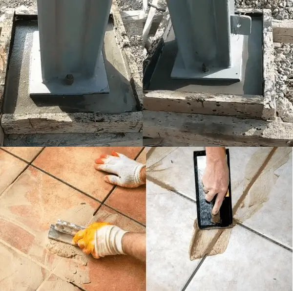
By carefully considering these factors and conducting proper research, you can select the most appropriate grouting material that meets your project’s requirements, ensuring the long-term effectiveness and performance of the grouting application. Fig. 1 below shows some typical grouting processes.
Fig. 1: Typical Grouting Processes
Grouting Injection Methods
Grouting injection methods refer to the techniques used to introduce grouting materials into voids, cracks, or spaces in construction materials. The selection of an appropriate injection method depends on factors such as the nature of the project, the characteristics of the grouting material, and the accessibility of the grouting area. Here are some common grouting injection methods:
Gravity Flow:
Gravity flow injection is the simplest and most basic method of grouting. It involves pouring or allowing the grouting material to flow under gravity into the targeted void or crack. This method is suitable for horizontal or vertical applications where the grout can naturally flow into the desired areas.
Hand Pumping:
Hand pumping is a manual injection method that involves using a handheld pump to inject grouting material. The grout is loaded into the pump, and pressure is applied manually to push the grout into the void or crack. Hand pumping is often used for smaller-scale applications or in areas where access is limited.
Mechanical Injection:
Mechanical injection methods use specialized equipment to inject grouting materials. Common mechanical injection methods include:
Piston Injection: Piston injection utilizes a hydraulic or pneumatic pump to generate pressure and force the grouting material into the voids. It is a versatile method suitable for various grouting applications, including soil stabilization, crack repair, or concrete repair.
Injection Packers: Injection packers are mechanical devices that are inserted into pre-drilled holes in the structure. They create a sealed connection and allow the grout to be injected under pressure. Injection packers are commonly used for injecting grout into cracks, joints, or voids in concrete structures.
Jet Grouting: Jet grouting involves high-pressure jets of grouting material that are directed into the ground to create columns or walls of compacted soil cement. It is often used for soil stabilization, ground improvement, or the creation of retaining walls.
Permeation Grouting:
Permeation grouting, also known as permeation or compaction grouting, is a method where low-viscosity grouts are injected under low pressure. The grout permeates the surrounding soil, filling voids and compacting loose or weak areas. Permeation grouting is commonly used for ground improvement, soil densification, or stabilizing loose soils.
Curtain Grouting:
Curtain grouting involves creating a grout curtain or barrier to prevent water infiltration. It is achieved by injecting grouting material along a specified path or perimeter. Curtain grouting is used in applications such as waterproofing tunnels, dams, or underground structures.
Preplaced Aggregate Grouting:
Preplaced aggregate grouting is a method used for large voids or rock fissures. It involves pre-filling the voids with aggregates and subsequently injecting the grout to fill the void spaces around the aggregates. This technique is commonly employed in rock formations or areas with significant voids.
The selection of the grouting injection method depends on factors such as project requirements, accessibility, desired grout distribution, and the characteristics of the grouting material. It is important to consult with experienced grouting professionals to determine the most suitable injection method for a specific application.
What is Compensation Grouting?
Compensation grouting is a specialized technique used in geotechnical engineering to mitigate ground settlement or heave caused by construction activities. It involves injecting grouting material into the ground to compensate for the anticipated ground movement, and maintaining the desired level or alignment of adjacent structures.
The purpose of compensation grouting is to balance the effects of excavation, tunneling, or other construction processes that induce ground movements. These ground movements can lead to settlement or heave, potentially affecting the stability of nearby structures, infrastructure, or the surrounding environment. Compensation grouting helps to minimize these effects and ensure the safety and integrity of the surrounding area.
The process of compensation grouting typically involves the following steps:
Monitoring: Before construction begins, a thorough geotechnical investigation and monitoring program is conducted. This involves assessing the soil conditions, measuring ground movement, and determining the potential impacts on nearby structures.
Design: Based on the monitoring data and analysis, a compensation grouting design is developed. This design specifies the injection locations, injection depths, grout type, injection pressures, and timing.
Injection: Grout is injected into predetermined locations using specialized equipment, such as grout pumps and injection pipes. The grouting material is injected under controlled pressure to fill the voids or gaps created by the ground movement. The injection process is closely monitored to ensure that the desired grout distribution is achieved.
Monitoring and Adjustments: The injected grout is monitored continuously to assess its effectiveness in compensating for ground movement. If necessary, adjustments may be made to the grouting program, such as altering injection volumes or locations, to optimize the compensation effect.
Compensation grouting can be performed using various types of grouting materials, including cementitious grouts, chemical grouts, or combinations of both. The selection of the grouting material depends on factors such as the soil conditions, the desired degree of control, and the specific project requirements.
Applications of compensation grouting can vary widely and include tunneling projects, deep excavations, mining operations, or any construction activity that may induce ground movements. By proactively injecting grout to counteract the expected ground displacements, compensation grouting helps to maintain the stability and safety of adjacent structures and infrastructure.
It is important to note that compensation grouting requires careful planning, monitoring, and expertise to ensure its effectiveness. Qualified geotechnical engineers and grouting specialists should be involved in the design, execution, and monitoring phases of compensation grouting projects to achieve optimal results.
What is Compaction Grouting?
Compaction grouting is a ground improvement technique used to stabilize or densify loose or weak soils. It involves injecting a low-slump, low-viscosity grout into the ground under high pressure. The grout displaces the surrounding soil, compacting it and increasing its strength and load-bearing capacity.
The primary objective of compaction grouting is to improve the engineering properties of the soil, enhance its stability, and reduce settlement or ground movement. It is commonly used in situations where loose or weak soils are unable to support the loads imposed by structures or where ground improvement is necessary to mitigate potential settlement issues.
What is Rock / Fissure Grouting?
Rock or fissure grouting is a specialized technique used to improve the stability and integrity of rock formations by injecting grout into fractures, joints, or fissures within the rock mass. It is commonly employed in geotechnical engineering, mining, tunneling, and other underground construction projects.
The primary objectives of rock or fissure grouting are to reduce water inflow, enhance rock mass strength, control ground movement, and increase the overall stability of the rock formation. By injecting grout into the fissures or fractures, the grout fills the voids, seals off water flow paths, and reinforces the rock mass.
Applications of Grouting
Grouting finds extensive applications in civil construction, including:
Foundation underpinning and soil stabilization.
Repair and rehabilitation of concrete structures.
Tunneling and mining operations.
Anchoring of bolts, dowels, or reinforcement bars.
Waterproofing and sealing of cracks, joints, or masonry walls.
Tile and stone installations.
Advantages of Grouting
The advantages of grouting include:
Enhanced Structural Integrity: Grouting reinforces the structural elements by filling voids, cracks, or gaps, thereby improving their load-bearing capacity and overall stability.
Increased Durability: Grouting helps protect construction materials, such as concrete or masonry, from moisture intrusion, chemical attacks, and other environmental factors, thus enhancing their durability and longevity.
Improved Waterproofing: By sealing cracks and joints, grouting prevents water infiltration, reducing the risk of damage caused by moisture and maintaining the integrity of the structure.
Enhanced Aesthetics: In tile installations, grouting not only provides functional benefits but also enhances the visual appeal by filling the gaps between tiles and creating a clean, finished appearance.
Flexibility and Versatility: With various types of grouts available, including cementitious, epoxy, urethane, and non-shrink grouts, grouting offers flexibility to meet specific project requirements and address different construction challenges.
Cost-Effective Solution: Grouting is a cost-effective method for repairing and rehabilitating structures, as it can help avoid the need for more extensive repairs or replacement of entire elements.
Reduced Downtime: Grouting processes can be completed relatively quickly, minimizing the downtime of the structure or area being grouted. This is particularly advantageous in industries where time is of the essence, such as mining or commercial construction.
Environmentally Friendly: Many grout materials are formulated to be environmentally friendly, with low volatile organic compound (VOC) emissions and minimal impact on the surrounding ecosystem.
Additional Information
Quality Control: Proper quality control measures, such as testing grout materials, monitoring injection pressures, and ensuring proper mixing and curing, are essential to achieve the desired results and ensure the longevity of the grouting applications.
Professional Expertise: Grouting techniques and processes can vary depending on the specific project requirements. Seeking the assistance of experienced professionals in grouting can ensure the proper selection of grout materials, precise application techniques, and adherence to industry standards.
Maintenance: Regular inspection and maintenance of grouted structures are crucial to identify any signs of deterioration, such as cracks, leaks, or grout loss. Timely repairs or re-grouting can prevent further damage and ensure the ongoing performance of the structure.
Grouting Cleaner
Grouting cleaner refers to a cleaning solution or product specifically designed for the cleaning and maintenance of grouted surfaces, such as tiled floors, walls, or countertops. The grouting cleaner is formulated to effectively remove dirt, stains, grime, and residues that accumulate on the grout lines over time.
Grouting cleaner typically comes in liquid form and may be available as a ready-to-use spray or concentrate that requires dilution with water. The specific composition of grouting cleaner can vary depending on the brand and product, but it generally contains a combination of surfactants, detergents, solvents, and sometimes mild acids or bleaching agents.
The purpose of grouting cleaner is to restore the appearance of grout lines, remove discoloration, and eliminate bacteria, mold, or mildew growth. It is important to regularly clean grout lines to maintain their original color, prevent staining, and ensure the longevity of the grout.
When using a grouting cleaner, it is advisable to follow the manufacturer’s instructions and take the following steps:
Preparing the Surface: Remove any loose dirt or debris from the grout lines using a soft brush or vacuum cleaner. This helps ensure that the cleaner can penetrate the grout effectively.
Applying the Grouting Cleaner: Spray or apply the grouting cleaner directly onto the grout lines, covering the desired area. Alternatively, if using a concentrate, dilute it with water as per the instructions and apply the solution to the grout lines using a sponge, brush, or mop.
Agitation: Allow the grouting cleaner to sit on the grout lines for the recommended dwell time specified by the manufacturer. During this time, you may need to lightly scrub or agitate the grout lines using a soft brush or scrub pad to help loosen dirt and stains.
Rinse: After the dwell time, thoroughly rinse the grout lines with clean water. This helps remove the cleaner and any loosened dirt or residues. For best results, ensure that all traces of the cleaning solution are completely removed.
Drying and Sealing (optional): Allow the grout lines to dry completely. If desired, you can apply a grout sealer to protect the grout from future staining and make future cleaning easier.
It is worth noting that certain grouting cleaners may be specifically formulated for different types of grout, such as cementitious or epoxy grout. Therefore, it is important to select a grouting cleaner that is compatible with the type of grout used in your specific application.
Regular cleaning and maintenance of grout lines using suitable grouting cleaners help preserve the appearance, cleanliness, and durability of tiled surfaces, ensuring they remain attractive and hygienic over time.
How to Clean Grouting in Floor Tiles?
Cleaning grout in floor tiles requires some effort, but with the right tools and techniques, you can restore the cleanliness and appearance of your grout lines. Here’s a step-by-step guide on how to clean grout in floor tiles:
Gather the necessary materials: You will need the following items for the cleaning process:
Grout cleaner (commercial cleaner or homemade solution)
Bristle brush or grout brush
An old toothbrush or small brush for hard-to-reach areas
Warm water
Sponge or microfiber cloth
Protective gloves (optional)
Preparing the area: Clear the floor area by removing any furniture or obstacles. This will provide easy access to the grout lines and ensure thorough cleaning.
Test the cleaner: Before applying the grout cleaner to the entire floor, perform a patch test in a small, inconspicuous area to ensure the cleaner doesn’t cause any adverse effects on the tiles or grout.
Apply the grout cleaner: Spray the grout cleaner directly onto the grout lines, covering the targeted areas. Alternatively, if using a homemade solution, prepare the mixture according to the instructions and apply it to the grout lines.
Allow the cleaner to penetrate: Let the grout cleaner sit on the grout lines for the recommended dwell time specified by the manufacturer. This allows the cleaner to loosen dirt, stains, and grime.
Scrub the grout lines: Use a bristle brush or grout brush to scrub the grout lines. Apply moderate pressure and scrub in a back-and-forth motion along the lines. Focus on one small section at a time to ensure thorough cleaning. For stubborn stains or tight spaces, use an old toothbrush or small brush to target those areas.
Rinse with warm water: After scrubbing, dampen a sponge or microfiber cloth with warm water and thoroughly rinse the grout lines. Rinse the sponge or cloth frequently to avoid spreading dirt back onto the grout.
Dry the floor: Use a dry microfiber cloth or towel to remove excess moisture from the floor. Ensure that the grout lines are adequately dried.
Optional: Apply a grout sealer: If desired, after the grout lines have completely dried, you can apply a grout sealer to protect them from future staining and make future cleaning easier. Follow the instructions on the sealer product for proper application.
Regular maintenance is key to keeping your grout lines clean. To prevent excessive dirt buildup and staining, sweep or vacuum the floor regularly and wipe up spills promptly.
Note: When using commercial grout cleaners, be sure to follow the manufacturer’s instructions and safety precautions. Some cleaners may require proper ventilation or the use of gloves.
By following these steps and maintaining regular cleaning practices, you can keep your grout lines in floor tiles clean and looking their best.
Conclusion
Grouting plays a vital role in civil construction, providing structural reinforcement, waterproofing, and aesthetic enhancement. With various grout types and application methods available, it is essential to choose the most suitable grout material and technique for each project. By understanding the purpose, process, types, and advantages of grouting, construction professionals can effectively utilize this technique to ensure the durability and integrity of their projects.
The oil and gas industry is one of the most critical sectors in global energy production. To ensure efficient and safe operations, various equipment and technologies are employed. Among these essential components are sight glasses, which play a vital role in monitoring processes and enhancing safety within the industry. Sight glasses provide visual access to observe fluids, gases, and their behaviors in equipment and pipelines. This article explores the significance, types, and applications of sight glasses in the oil and gas industry.
What is a Sight Glass?
A sight glass, also known as a sight window, viewport, or sight port window, is a specialized type of transparent visual window for observing working fluids at high temperatures and pressures. Widely used in tanks, process vessels, boilers, reactors, and many other industrial equipments, Sight glasses are made from robust glass materials that can resist such extreme environments. One can use these sight glasses to look at the process inside the equipment safely. Resembling a glass disc between two metal frames, sight glasses are strong enough to break or usual failures.
Importance of Sight Glasses
In oil and gas facilities, the ability to visually inspect processes, fluids, and equipment is invaluable. Sight glasses allow operators and maintenance personnel to monitor
fluid levels,
flow rates,
color changes,
phase separations,
production stages,
fluid quality, and
the presence of contaminants or bubbles.
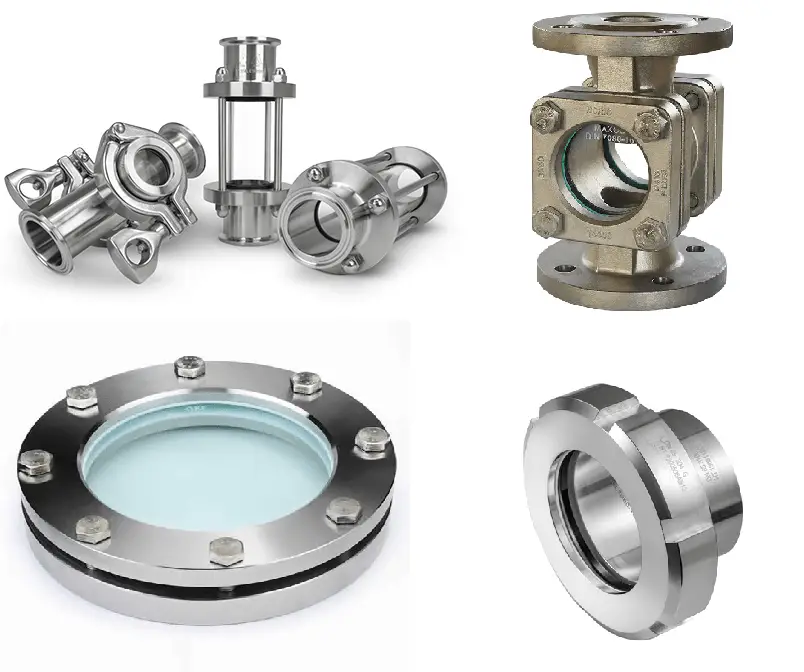
These observations help identify potential issues, such as leaks, pressure imbalances, or equipment malfunctions without having to open the equipment which allows for timely interventions and preventing costly downtime or hazardous situations. Fig. 1 below shows some typical sight glasses:
Fig. 1: Typical Sight Glasses
Types of Sight Glasses
Transparent Sight Glasses:
These sight glasses are made from materials such as tempered borosilicate glass or polycarbonate. They offer excellent visibility, high resistance to chemicals and thermal shock, and are suitable for high-pressure applications. Transparent sight glasses are commonly used in storage tanks, pipelines, and process vessels.
Reflex Sight Glasses:
Reflex sight glasses have a prism on one side that refracts light, resulting in a contrast difference when viewed from different angles. The change in appearance indicates the presence or absence of fluid within the sight glass. These glasses are advantageous when dealing with transparent fluids, as they enhance visibility by highlighting the fluid level. Reflex sight glasses are commonly used in low-pressure applications and steam systems.
Magnetic Sight Glasses:
Magnetic sight glasses incorporate a magnetic strip or float inside a glass tube. As the fluid level changes, the position of the magnetic float varies, providing a visual indication of the level. These sight glasses are particularly useful when dealing with opaque or hazardous fluids, as they eliminate the need for direct contact with the medium. Magnetic sight glasses are widely used in oil separators, compressor systems, and hydraulic reservoirs.
Again depending on the construction of the sight glasses there are two types of sight glasses that are used in the oil and gas industries. they are:
Conventional glass disc window sight glass which consists of a glass disc sandwiched between two gasketed metal rings suitable for low-pressure and non-critical processes; and
A fused sight glass for high-performance applications where the glass window is fused to the metal carrier ring during its construction.
Materials for Sight Glasses
Depending on the application environment requirements, various types of glass materials are used for making sight glasses.
For low-pressure-temperature, non-critical applications sight glass windows are manufactured from standard soda lime glass. For a temperature of up to 536°F, borosilicate glass (Pyrex®) or acrylic plastics are used for constructing sight glass windows.
For equipment involving temperatures above 536°F, sight glass windows are generally made using quartz or sapphire glass. these materials are thermal shock or corrosion-resistant.
For some sanitary processing applications, high-grade specialty plastics such as acrylic (plexiglass or PMMA (Polymethyl methacrylate)) or polycarbonates are used for making sight glasses.
The metallic frames are normally made from stainless steel. So the materials used for constructing sight glasses can be summarized as follows:
Borosilicate Glass: Borosilicate glass, such as the popular brand Pyrex®, is widely used in sight glasses. It offers excellent clarity, high resistance to thermal shock, and good chemical compatibility with a wide range of fluids. Borosilicate glass is suitable for both low and high-pressure applications and is often used in transparent sight glasses.
Tempered Glass: Tempered glass is heat-treated glass that is stronger and more impact-resistant than standard glass. It undergoes a controlled heating and rapid cooling process to increase its strength. Tempered glass sight glasses are preferred in applications where there is a higher risk of mechanical stress or impact, such as in industrial environments.
Polycarbonate: Polycarbonate is a durable, lightweight, and shatter-resistant thermoplastic material. It offers excellent impact resistance and is often used as a safer alternative to glass in applications where the risk of breakage is high. Polycarbonate sight glasses are commonly used in industries where safety is a priority, such as oil and gas, chemical processing, and food processing.
Acrylic: Acrylic, also known as plexiglass or PMMA (Polymethyl methacrylate), is a transparent thermoplastic material. It offers good optical clarity, and impact resistance, and is lighter than glass. Acrylic sight glasses are commonly used in lower-pressure and temperature applications where chemical resistance is not a critical requirement.
Stainless Steel: In some cases, sight glasses may have metal frames or housings, especially when the operating conditions are severe or the sight glass is exposed to corrosive environments. Stainless steel is often used for such applications due to its high strength, corrosion resistance, and durability. Stainless steel sight glasses are commonly used in oil and gas equipment, chemical processing, and offshore installations.
Teflon (PTFE): Teflon, or polytetrafluoroethylene (PTFE), is a fluoropolymer known for its excellent chemical resistance. It is often used as a gasket or sealing material in sight glasses to provide a reliable and leak-free connection between the glass and surrounding equipment for low-temperature applications.
Selecting Sight Glasses
Selecting the right sight glass for a specific application requires careful consideration of several factors. These factors include:
Fluid Compatibility:
The sight glass material must be compatible with the fluid being observed. Some fluids may be corrosive, abrasive, or reactive with certain materials. It is crucial to choose a sight glass material that can withstand the chemical properties of the fluid without degradation or damage.
Pressure and Temperature:
Consider the operating pressure and temperature of the system where the sight glass will be installed. The sight glass should be able to withstand mechanical stress and thermal conditions (thermal shock) without compromising its integrity or visibility. Ensure that the selected sight glass has an appropriate pressure and temperature rating for the application.
Visibility and Clarity:
The visibility requirements of the application should be considered. Some applications may require high clarity and transparency to observe fine details or color changes in the fluid. In such cases, materials like borosilicate glass or tempered glass are preferred. Assess the optical properties of the sight glass material to ensure it provides the desired visibility.
Mechanical Strength and Impact Resistance:
Depending on the application, the sight glass may be subject to mechanical stress or impact. Consider the robustness and strength of the selected material to ensure it can withstand the anticipated forces without breaking or cracking. Tempered glass or polycarbonate are often chosen for applications requiring high-impact resistance.
Safety Considerations:
Safety is paramount in the oil and gas industry. Evaluate the risk of potential accidents, such as glass breakage, and consider materials that minimize the hazards associated with shattered glass. Polycarbonate or acrylic, which are shatter-resistant materials, may be preferred in safety-critical applications.
Environmental Factors:
Assess the environmental conditions surrounding the sight glass installation. Factors such as exposure to harsh chemicals, UV radiation, extreme weather conditions, or abrasive particles may impact the longevity and performance of the sight glass. Choose a material that can withstand these environmental factors and ensure its durability.
Regulatory and Industry Standards:
Consider any applicable regulatory requirements or industry standards for sight glass selection. Some industries, such as oil and gas, may have specific guidelines or standards that dictate the use of certain materials or designs. Ensure compliance with relevant regulations and standards to maintain operational and safety standards.
Maintenance and Cleaning:
Evaluate the ease of maintenance and cleaning for the selected sight glass material. Some materials may require specialized cleaning procedures or have restrictions on cleaning agents. Consider the accessibility of the sight glass for routine inspections and maintenance activities.
Specifying a Sight Glass
Specifying a sight glass involves providing detailed information and requirements to ensure that the selected sight glass meets the specific needs of the application. Here is the key information to specify a sight glass effectively:
Application Details: Clearly define the application where the sight glass will be used. Understand the purpose of the sight glass, whether it is for monitoring fluid levels, observing flow patterns, or detecting the presence of contaminants. Identify the specific equipment or system where the sight glass will be installed, such as storage tanks, pipelines, reactors, or separators.
Operating Conditions: Provide information about the operating conditions of the system. This includes factors such as pressure range, temperature range, and the type of fluid or media being observed. Note any potential variations or fluctuations in pressure or temperature that the sight glass may encounter during operation.
Sight Glass Type: Determine the most suitable type of sight glass based on the application requirements and operating conditions. Consider factors such as transparency needs, pressure rating, and the ability to detect specific fluid properties (e.g., color changes, fluid level). Choose from options such as transparent sight glasses, reflex sight glasses, or magnetic sight glasses.
Material Requirements: Based on the fluid compatibility, pressure, temperature, and visibility requirements, specify the appropriate sight glass material. Consider factors such as chemical resistance, mechanical strength, impact resistance, and safety considerations. Common materials include borosilicate glass, tempered glass, polycarbonate, or acrylic.
Specify Dimensions and Connections: Provide the required dimensions of the sight glass, including the diameter or length of the glass tube or window. Specify the connections or fittings needed to integrate the sight glass into the equipment or system, such as threaded, flanged, or welded connections.
Consider Additional Features: Determine if any additional features are necessary for the sight glass. This may include protective coatings for enhanced chemical resistance, special gaskets or seals, lighting arrangements for improved visibility, or pressure relief devices. Specify any specific requirements or preferences for these additional features.
Compliance and Standards: Ensure that the specified sight glass complies with applicable industry standards, regulations, and safety guidelines. Consider any specific certifications or approvals required for the sight glass, especially in safety-critical applications.
Quantity and Delivery Timeframe: Specify the number of sight glasses you require, as well as any specific delivery timeframe or schedule. This will help the vendor provide accurate pricing and determine their ability to meet your timeline.
Any Other Relevant Information: Provide any additional relevant information that might assist the vendor in understanding your requirements accurately. This may include any specific preferences, previous experiences, or challenges you have encountered with similar equipment.
Applications of Sight Glasses in the Oil and Gas Industry
Storage Tanks and Vessels:
Sight glasses allow operators to monitor liquid levels, flow patterns, and the presence of sediments or contaminants in storage tanks and vessels. By providing real-time visual information, sight glasses help optimize storage capacity, prevent overflow or underfilling, and ensure the quality of stored materials.
Reactors and Separators:
Sight glasses provide a direct view into reactors and separators, allowing operators to observe chemical reactions, phase separations, and the accumulation of impurities or byproducts. Monitoring these processes in real-time facilitates adjustments to operating conditions and helps maintain the efficiency and safety of the equipment.
Piping Systems:
Sight glasses installed in pipelines aid in the detection of leaks, blockages, or changes in fluid behavior. By visually inspecting the flow, operators can identify issues such as turbulence, cavitation, or the formation of hydrates, enabling prompt maintenance and preventing system failures.
Offshore and Subsea Applications:
In offshore and subsea oil and gas operations, sight glasses are used to monitor the condition of subsea equipment, pipelines, and risers. By visually inspecting these critical components, operators can detect corrosion, fouling, or the presence of hydrates or blockages, ensuring the integrity and reliability of subsea infrastructure.
The industries that widely use sight glasses are:
Oil & Gas
Chemical & Petrochemical
Food & Beverage
Biofuels
Pharmaceutical
Utility Industry
Biogas
Biotech
Wastewater Treatment
What is a Boiler Sight Glass?
A boiler sight glass, also known as a sight gauge or water level gauge, is a transparent tubular device used to visually monitor the water level inside a boiler or steam generator. It provides a direct indication of the water level, allowing operators to ensure the safe and efficient operation of the boiler.
The boiler sight glass typically consists of a glass tube or window mounted on the boiler’s water drum or steam drum. The glass tube is usually made of tempered borosilicate glass, which is able to withstand high temperatures and pressure. The sight glass is installed at a convenient location on the boiler, allowing operators to easily observe the water level. The sight glass operates on the principle of communicating vessels. As the water level inside the boiler changes, the water level in the sight glass also rises or falls accordingly. By observing the position of the water level in the sight glass, operators can determine if the boiler has sufficient water for safe operation or if it needs to be replenished.
What is a Tank Sight Glass?
A tank sight glass, also known as a liquid level gauge or tank level indicator, is a transparent device used to visually monitor the liquid level inside a storage tank or vessel. It provides a direct indication of the fluid level, allowing operators to monitor inventory, prevent overfilling or underfilling, and ensure efficient operation of the tank.
Tank sight glasses typically consist of a transparent glass or plastic tube or window installed on the side or top of the tank. The material used for the sight glass depends on the specific application and the properties of the fluid being stored. The sight glass is connected to the tank through fittings or flanges, allowing the liquid to reach the same level inside the sight glass as it does in the tank.
Conclusion
Sight glasses play a crucial role in the oil and gas industry, enabling operators and maintenance personnel to visually monitor processes, fluids, and equipment. By providing real-time visibility, sight glasses contribute to enhanced efficiency, improved safety, and timely interventions to prevent costly downtime or hazardous situations. The availability of different types of sight glasses allows for their widespread use in various applications, including storage tanks, piping systems, reactors, and offshore operations. Incorporating sight glasses as an integral part of oil and gas infrastructure is a prudent investment that ensures the industry’s smooth functioning while minimizing risks and maximizing operational performance.
Types of Plumbing Pipes: Their Advantages, Features, and Applications
Plumbing systems play a vital role in our homes, ensuring the delivery of clean water and the proper disposal of waste. While the functionality of plumbing largely depends on a network of pipes, it’s crucial to understand that not all pipes are created equal. Different types of plumbing pipes offer varying levels of durability, longevity, and suitability for specific applications. In this article, we will explore the most common types of plumbing pipes and their unique characteristics to help you make informed decisions for your plumbing needs.
Copper Pipes
Copper pipes have long been the gold standard in plumbing due to their excellent corrosion resistance, durability, and versatility. They are available in rigid or flexible forms, making them suitable for both water supply and drainage systems. Copper pipes are known for their longevity, often outlasting the lifespan of other plumbing materials. They are also resistant to high temperatures, making them ideal for both hot and cold water applications. However, copper pipes can be relatively expensive and may require skilled labor for installation.
Advantages of Copper Pipes
Here are some key features and advantages of copper pipes:
Corrosion Resistance: Copper pipes are highly resistant to corrosion, making them ideal for carrying water and other fluids. They do not rust or deteriorate over time, ensuring long-lasting performance and reliability.
Durability: Copper pipes have a long lifespan and can often outlast the buildings they are installed in. They are strong and can withstand high water pressures without bursting or leaking. Copper pipes are also resistant to UV rays, making them suitable for both indoor and outdoor applications.
Heat Resistance: Copper pipes have excellent heat resistance, making them ideal for both hot and cold water supply systems. They can effectively handle high-temperature water without warping or degrading. This heat resistance makes copper pipes suitable for applications such as hot water heaters and radiant heating systems.
Flexibility: Copper pipes can be easily shaped and bent to fit various plumbing layouts and configurations. They are available in both rigid and flexible forms, providing versatility in installation. Copper pipes can be soldered or joined using compression fittings, allowing for secure and leak-free connections.
Antibacterial Properties: Copper has natural antibacterial properties, which can help inhibit the growth of bacteria, viruses, and fungi in the plumbing system. This can contribute to maintaining a clean and hygienic water supply.
Recyclability: Copper is a highly recyclable material. When copper pipes reach the end of their useful life, they can be recycled and repurposed, reducing environmental impact and promoting sustainability.
Applications of Copper Pipes
Copper pipes are commonly used in various plumbing applications, including:
Water Supply Lines: Copper pipes are widely used for both residential and commercial water supply systems. They are suitable for carrying potable water, ensuring clean and safe drinking water for households and buildings.
Plumbing Fixtures: Copper pipes are used to connect plumbing fixtures, such as faucets, showers, toilets, and sinks, to the main water supply lines. Their flexibility allows for easy installation in tight spaces.
Heating Systems: Copper pipes are often used in hydronic heating systems and radiant floor heating systems. Their heat conductivity and resistance make them efficient for distributing hot water throughout the system.
It’s important to note that copper pipes can be more expensive than other types of plumbing pipes. They also require skilled labor and specialized tools for installation. Additionally, in areas with aggressive water conditions or high acidity, copper pipes may require additional protective measures, such as water treatment or pipe insulation.
Overall, copper pipes are a popular choice for plumbing systems due to their durability, corrosion resistance, heat resistance, and longevity. When properly installed and maintained, copper pipes can provide a reliable and efficient water supply and contribute to the overall functionality of the plumbing system.
Fig. 1: Plumbing Pipe Types
PEX Pipes
Cross-linked polyethylene (PEX) pipes have gained popularity in recent years due to their flexibility, ease of installation, and affordability. PEX pipes are highly resistant to freezing temperatures and are less likely to burst compared to copper or rigid plastic pipes. They can be easily bent and curved around obstacles, reducing the need for complicated fittings. PEX pipes are commonly color-coded to differentiate between hot and cold water lines. It’s worth noting that PEX pipes should not be exposed to direct sunlight as it can degrade the material over time.
Benefits of PEX Pipes
Here are some key features and benefits of PEX pipes:
Flexibility: PEX pipes are highly flexible, allowing for easy installation in various plumbing layouts. They can be bent and curved around obstacles, reducing the need for complex fittings and minimizing the potential for leaks. The flexibility of PEX pipes also makes them suitable for retrofitting or remodeling projects.
Freeze Resistance: PEX pipes have excellent freeze resistance, making them ideal for cold weather climates. They can expand and contract without cracking or bursting when exposed to freezing temperatures. This feature reduces the risk of costly water damage and simplifies winterization procedures.
Durability: PEX pipes are highly durable and resistant to common plumbing issues such as corrosion, scale buildup, and pitting. They can withstand high water pressures and are less likely to develop pinhole leaks over time. PEX pipes also have excellent resistance to chemicals, ensuring a long lifespan.
Easy Installation: PEX pipes are relatively easy to install, even for individuals with basic plumbing knowledge. They can be cut with a simple tubing cutter and require fewer fittings compared to rigid pipes. PEX pipes can be connected using various methods, including crimping, clamping, or push-fit fittings, which simplifies the installation process.
Versatility: PEX pipes are suitable for a wide range of plumbing applications. They can be used for both hot and cold water supply lines, including potable water distribution. PEX pipes are also commonly used for radiant floor heating systems and hydronic heating applications.
Reduced Noise Transmission: PEX pipes have natural sound-dampening properties, minimizing the noise associated with water flow. This makes them an excellent choice for applications where noise reduction is desired, such as residential buildings or multi-story structures.
It’s important to note that while PEX pipes are highly versatile, they should not be exposed to direct sunlight for extended periods as they can degrade the material. UV-resistant PEX pipes or proper insulation should be used for outdoor or exposed installations.
When working with PEX pipes, it’s crucial to follow local plumbing codes and guidelines. Proper tools, fittings, and installation techniques should be used to ensure secure and watertight connections. It’s advisable to consult with a professional plumber or plumbing engineer if you have specific questions or concerns about using PEX pipes for your plumbing project.
In summary, PEX pipes offer a flexible, durable, and freeze-resistant solution for plumbing systems. Their ease of installation and suitability for various applications make them a popular choice among homeowners and professionals alike.
PVC Pipes
Polyvinyl chloride (PVC) pipes are widely used for drainage systems and non-potable water applications. They are lightweight, durable, and resistant to chemicals, making them suitable for various plumbing needs. PVC pipes are relatively inexpensive and easy to install. However, they are not recommended for hot water applications as they can warp under high temperatures. Additionally, PVC pipes may become brittle over time, especially when exposed to extreme cold.
Advantages of PVC Pipes
Here are some key features and benefits of PVC pipes:
Affordability: PVC pipes are relatively inexpensive compared to other types of plumbing pipes. This makes them a cost-effective option for plumbing projects, whether it’s for residential, commercial, or industrial applications.
Durability: PVC pipes are highly durable and resistant to corrosion, rust, and chemical degradation. They can withstand high water pressures without leaking or bursting, providing a long-lasting plumbing solution.
Lightweight: PVC pipes are lightweight, which makes them easy to handle and install. Their lightness reduces the strain on the overall plumbing system and simplifies transportation during construction or renovation projects.
Easy Installation: PVC pipes are easy to work with and install. They can be cut to desired lengths using a saw or PVC pipe cutter and joined together using solvent cement or compression fittings. PVC pipes require fewer fittings and connections, resulting in simpler and quicker installation.
Chemical Resistance: PVC pipes have excellent chemical resistance, making them suitable for a wide range of plumbing applications. They can withstand exposure to various household chemicals and are commonly used for both potable water supply and drainage systems.
Insulation: PVC pipes have good thermal insulation properties, which means they help maintain the temperature of the fluid flowing through them. This can be beneficial in both hot and cold water applications, helping to conserve energy and improve efficiency.
Wide Range of Applications: PVC pipes are versatile and used in various plumbing applications. They are commonly used for water supply lines, drainage systems, wastewater disposal, irrigation systems, and venting applications.
However, it’s important to note that PVC pipes have temperature limitations. They are not suitable for carrying hot water above a certain temperature threshold, as high temperatures can cause the material to deform or weaken. For hot water applications, alternative materials like CPVC (chlorinated polyvinyl chloride) pipes may be more appropriate.
When working with PVC pipes, it is important to follow local building codes and guidelines. Proper solvent cementing techniques and appropriate fittings should be used to ensure leak-free connections. Additionally, PVC pipes should be protected from prolonged exposure to direct sunlight as ultraviolet (UV) rays can degrade the material over time. Outdoor installations should be done with UV-resistant PVC pipes or appropriate pipe insulation.
In conclusion, PVC pipes are a popular choice for plumbing systems due to their affordability, durability, and ease of installation. They provide a reliable and cost-effective solution for various plumbing needs, making them widely used in residential, commercial, and industrial applications.
Fig. 2: Types of Plumbing Pipes
CPVC Pipes
Chlorinated polyvinyl chloride (CPVC) pipes are a variant of PVC pipes that have been treated with chlorine to increase their temperature resistance. CPVC pipes are commonly used for hot water supply lines and are suitable for both residential and commercial applications. They offer excellent corrosion resistance and are relatively easy to install. However, it’s important to note that CPVC pipes require specific solvent cement for proper joint connections.
Benefits of CPVC Pipes
Here are some key features and benefits of CPVC pipes:
Temperature Resistance: CPVC pipes are designed to withstand higher temperatures compared to standard PVC pipes. They can handle hot water at temperatures up to 200°F (93°C) without deforming or weakening, making them suitable for hot water supply lines.
Corrosion Resistance: CPVC pipes are highly resistant to corrosion from hot water and aggressive chemicals. They are less prone to scaling, pitting, and degradation, ensuring a long lifespan and reliable performance in hot water applications.
Durability: CPVC pipes are known for their strength and durability. They can withstand high water pressures and mechanical stresses without leaking or bursting. CPVC pipes also have good impact resistance, reducing the risk of damage during installation or use.
Chemical Resistance: CPVC pipes have excellent chemical resistance, making them suitable for various applications where hot water is in contact with chemicals or aggressive substances. They can handle a wide range of acids, bases, and solvents commonly found in plumbing systems.
Easy Installation: CPVC pipes are lightweight and easy to install, similar to PVC pipes. They can be cut, joined, and connected using solvent cement or mechanical fittings. CPVC pipes require fewer supports compared to metal pipes due to their lightweight nature.
Cost-Effective: CPVC pipes offer a cost-effective solution for hot water plumbing systems. They are generally more affordable than metal pipes such as copper or stainless steel, making them a popular choice for residential and commercial projects.
Applications of CPVC Pipes
CPVC pipes are commonly used in a range of hot water applications, including:
Hot Water Supply Lines: CPVC pipes are suitable for carrying hot water from the water heater to faucets, showers, and other hot water fixtures. They provide a reliable and efficient distribution system for hot water in residential and commercial buildings.
Industrial Applications: CPVC pipes are used in various industrial processes that involve hot water transport, such as in manufacturing plants, chemical processing facilities, and food production facilities.
Sprinkler Systems: CPVC pipes are also used in fire sprinkler systems, where hot water or a mixture of water and antifreeze is circulated to provide fire protection.
It’s important to note that CPVC pipes should not be used for drinking water applications, as they can impart a slight taste or odor to the water. For potable water supply lines, it’s recommended to use CPVC pipes for hot water lines only and use approved materials like PVC or copper for cold water lines.
When working with CPVC pipes, it is crucial to follow manufacturer instructions, local plumbing codes, and guidelines. Proper solvent cementing techniques and appropriate fittings should be used to ensure secure and leak-free connections. Consulting with a professional plumber or plumbing engineer is advisable for specific projects or complex installations.
In summary, CPVC pipes are specifically designed for hot water applications, offering excellent temperature resistance, corrosion resistance, and durability. They provide a reliable and cost-effective solution for distributing hot water in residential, commercial, and industrial plumbing systems.
Galvanized Steel Pipes: Galvanized Iron Pipes
Galvanized steel pipes were once a popular choice for plumbing, but they are now less commonly used due to their drawbacks. These pipes are coated with a layer of zinc to prevent corrosion. While galvanized steel pipes are durable and have a long lifespan, they are prone to rust and can accumulate mineral deposits over time, leading to reduced water flow. Moreover, galvanized steel pipes are challenging to work with and may require professional assistance for installation or repairs.
Advantages of Galvanized Iron Pipes
Here are some key features and characteristics of galvanized iron pipes:
Corrosion Resistance: The primary purpose of galvanizing is to provide corrosion resistance to the underlying iron or steel material. The zinc coating acts as a sacrificial layer, protecting the iron or steel from rust and corrosion caused by exposure to water and other corrosive substances. This corrosion resistance makes galvanized iron pipes suitable for plumbing systems, particularly in areas with high levels of moisture.
Durability: Galvanized iron pipes are known for their durability and ability to withstand high water pressures. They have a long lifespan and can handle demanding plumbing applications.
Strength: Galvanized iron pipes are strong and rigid, making them suitable for applications where structural integrity is essential. They can withstand heavy loads and are commonly used for water distribution in buildings and outdoor plumbing installations.
Temperature Resistance: Galvanized iron pipes have good temperature resistance and can handle both hot and cold water. However, prolonged exposure to high temperatures can cause the zinc coating to deteriorate, leading to reduced corrosion protection.
Installation Challenges: Galvanized iron pipes can be challenging to work with during installation due to their weight and rigidity. They often require threaded fittings for connections, which can be time-consuming and may require professional assistance. Additionally, the threads on galvanized pipes can be prone to leakage over time.
Maintenance Considerations: Over time, the zinc coating on galvanized iron pipes may wear away or develop cracks, exposing the underlying iron or steel to corrosion. Regular inspection and maintenance are necessary to identify and address any signs of corrosion, such as rust stains or leaks.
It’s important to note that the use of galvanized iron pipes for potable water systems is no longer recommended in many jurisdictions due to potential health concerns. As the zinc coating ages, it can release small amounts of zinc into the water, which may pose health risks if consumed over time. Modern plumbing standards often require the use of alternative materials, such as copper, PVC, or PEX, for potable water supply.
In summary, galvanized iron pipes were once a common choice for plumbing systems due to their corrosion resistance and durability. However, their use has declined in recent years due to potential health concerns, installation challenges, and the availability of more advanced materials. It’s advisable to consult with a professional plumber or adhere to local plumbing codes and regulations when considering the use of galvanized iron pipes in plumbing projects.
Polyethylene Pipes
Polyethylene (PE) pipes are commonly used for underground water supply lines and irrigation systems. They are highly resistant to chemicals, corrosion, and abrasion. PE pipes come in various types, such as HDPE (high-density polyethylene) and MDPE (medium-density polyethylene), each with different strengths and applications. These pipes are lightweight, flexible, and relatively easy to install. However, they are not suitable for hot water applications due to their lower temperature resistance.
Benefits of Polyethylene Pipes
Here are some key features and benefits of polyethylene pipes:
Durability: Polyethylene pipes are known for their exceptional durability. They have high resistance to cracking, impact, and abrasion, making them suitable for challenging environments and underground installations. PE pipes have a long lifespan and can withstand prolonged exposure to harsh conditions, including UV rays and chemicals.
Corrosion Resistance: Polyethylene pipes are highly resistant to corrosion and chemical attack. They do not rust or corrode like metallic pipes, making them suitable for transporting various substances, including potable water, wastewater, chemicals, and gases.
Flexibility: PE pipes are flexible, which allows for easy installation and versatility in plumbing applications. They can be coiled and bent to accommodate changing terrain or irregular layouts. The flexibility of PE pipes reduces the need for multiple fittings and joints, reducing the potential for leaks.
Lightweight: Polyethylene pipes are lightweight compared to metallic pipes, which makes handling and installation easier and more cost-effective. The reduced weight also contributes to lower transportation costs and less strain on the overall plumbing system.
High Flow Capacity: PE pipes have smooth internal surfaces that facilitate excellent flow characteristics. They offer low friction losses and allow for efficient fluid transport, ensuring optimal performance in plumbing systems.
Thermal Insulation: Polyethylene pipes provide some degree of thermal insulation. They have low thermal conductivity, which helps to maintain the temperature of the fluid being transported. This feature can be advantageous in applications where temperature control is important, such as chilled water systems.
Leak Resistance: The joints and connections in PE pipes are typically fused or welded together, creating strong, leak-resistant connections. This eliminates the need for external fittings or adhesive materials, reducing the potential points of failure and ensuring a reliable plumbing system.
Applications of Polyethylene Pipes
Polyethylene pipes are commonly used in various applications, including:
Water Supply Systems: PE pipes are widely used for water supply networks, both for potable water and non-potable water applications. They can be employed for residential, commercial, and industrial water distribution systems.
Irrigation Systems: Polyethylene pipes are well-suited for irrigation systems due to their resistance to chemicals, abrasion, and weather conditions. They are commonly used for agricultural irrigation, landscaping projects, and golf course irrigation.
Gas Distribution: PE pipes are used for natural gas and propane distribution. They provide a safe and reliable means of transporting gas, with excellent resistance to corrosion and gas permeation.
Industrial Applications: Polyethylene pipes find applications in various industrial sectors, such as mining, chemical processing, and oil and gas industries. They are used for transporting chemicals, slurries, and other fluids.
It’s important to note that different types of polyethylene pipes, such as HDPE and MDPE, have specific application guidelines and limitations. Adhering to the manufacturer’s recommendations and local plumbing codes is essential to ensure proper installation and usage of PE pipes.
In summary, polyethylene pipes offer durability, corrosion resistance, flexibility, and lightweight properties, making them a versatile choice for various plumbing applications. Their ability to withstand harsh conditions and provide efficient fluid transport makes them a reliable and cost-effective option for plumbing systems.
CSST Pipes
CSST stands for Corrugated Stainless Steel Tubing. It is a type of flexible piping used for gas distribution in residential, commercial, and industrial buildings. CSST pipes are made of thin-walled stainless steel tubing with a corrugated or ribbed outer layer. This corrugated design provides flexibility, allowing the pipe to be easily bent and routed around obstacles during installation.
Advantages of CSST Pipes
CSST pipes are commonly used to connect gas appliances, such as stoves, furnaces, water heaters, and fireplaces, to the main gas supply line. They offer several advantages over traditional rigid black iron or copper pipes:
Flexibility: CSST pipes are highly flexible, making them easier to install compared to rigid pipes. They can be bent and shaped to fit around corners, through tight spaces, and around other structural elements, reducing the need for additional fittings and joints.
Corrosion Resistance: CSST pipes are made of stainless steel, which provides excellent resistance to corrosion and rust. This makes them suitable for both indoor and outdoor installations, including areas prone to moisture or harsh environmental conditions.
Lightweight: CSST pipes are significantly lighter than traditional rigid pipes, making them easier to handle and transport during installation. Their lightweight nature also reduces the strain on the overall gas distribution system.
Reduced Labor and Installation Time: The flexibility and ease of installation of CSST pipes contribute to reduced labor and installation time. With fewer fittings and joints required, installation becomes quicker and more efficient, resulting in cost savings for both residential and commercial projects.
Safety Features: CSST pipes are designed with safety features to withstand high-pressure events. They have a protective jacket or coating that helps prevent damage from external factors, such as UV rays, moisture, and chemicals. Additionally, CSST pipes are often equipped with an electrical bonding system to provide protection against potential electrical arcing caused by nearby lightning strikes.
It’s important to note that CSST pipes should be installed and handled by qualified professionals who are familiar with local building codes and regulations. Proper installation techniques, including appropriate support, bonding, and grounding, are crucial to ensure the safe and reliable operation of CSST systems.
CSST pipes have gained popularity in the gas distribution industry due to their flexibility, ease of installation, and corrosion resistance. However, it’s essential to consult with a licensed professional plumber or gas fitter to determine the suitability of CSST pipes for your specific application and to ensure compliance with local building codes and regulations.
ABS Pipes
ABS stands for Acrylonitrile Butadiene Styrene. ABS pipes are a type of plastic piping commonly used in residential and commercial plumbing systems. They are known for their durability, chemical resistance, and ease of installation. ABS pipes are typically black in color and have a smooth surface.
Advantages of ABS Pipes
Here are some key features and uses of ABS pipes:
Durability: ABS pipes are known for their strength and durability. They can withstand high impact and pressure, making them suitable for various plumbing applications. ABS pipes are resistant to cracking and are less likely to shatter compared to other types of plastic pipes.
Chemical Resistance: ABS pipes are highly resistant to chemicals, making them suitable for a wide range of plumbing applications. They can handle common household chemicals and are less likely to corrode or degrade when exposed to aggressive substances.
Lightweight: ABS pipes are lightweight, making them easy to handle and install. This characteristic can significantly reduce labor and installation costs, especially in large plumbing projects.
Noise Reduction: ABS pipes have excellent sound-dampening properties. They help reduce the noise caused by water flow within the plumbing system, making them ideal for applications where noise reduction is desired, such as residential and multi-story buildings.
Ease of Installation: ABS pipes are relatively easy to work with and can be installed using simple tools and techniques. They can be cut, joined, and connected using solvent cement, making installation quick and efficient.
Non-Toxic: ABS pipes are non-toxic and safe for carrying potable water. They do not leach harmful chemicals into the water supply, ensuring the delivery of clean and safe drinking water.
Applications of ABS Pipes
ABS pipes are commonly used for various plumbing applications, including:
Drainage Systems: ABS pipes are often used for residential and commercial drainage systems, including soil and waste pipes. They effectively transport wastewater from sinks, toilets, and showers to the main sewer or septic system.
Ventilation Systems: ABS pipes are also used for ventilation and air circulation systems. They can be installed to provide proper airflow and prevent the buildup of harmful gases, such as methane and sewer gases.
Plumbing Fixtures: ABS pipes are suitable for connecting plumbing fixtures, such as toilets, sinks, and bathtubs, to the main plumbing system.
It’s important to note that ABS pipes are not recommended for hot water applications. They have a lower temperature resistance compared to other piping materials like CPVC or copper. Therefore, ABS pipes are primarily used for cold water supply and drainage systems.
When working with ABS pipes, it is crucial to follow local plumbing codes and guidelines and use appropriate fittings and solvent cement for secure and leak-free connections. If you are unsure about the suitability of ABS pipes for your specific plumbing needs, it is advisable to consult with a professional plumber or plumbing engineer.
Black Pipes
Black pipes, also known as black iron pipes or black steel pipes, are a type of rigid steel piping commonly used in plumbing and gas distribution systems. They are called “black” due to their dark appearance, which is a result of a black oxide scale on their surface.
Here are some key features and characteristics of black pipes:
Material: Black pipes are typically made of mild steel, which is an alloy of iron and carbon. The carbon content gives the steel strength and rigidity, making it suitable for plumbing applications that require durability and resistance to high water pressures or gas distribution.
Strength and Durability: Black pipes are known for their strength and durability. They can withstand high water pressures and are suitable for various plumbing applications, including water supply lines and gas distribution systems. Black pipes are often preferred for outdoor and underground installations due to their robustness and resistance to external forces.
Corrosion Resistance: Black pipes are not inherently resistant to corrosion. Without any protective coating, they are vulnerable to rust and degradation when exposed to moisture and oxygen over time. As a result, black pipes are typically used for applications that do not require corrosion resistance, such as gas distribution, where a protective coating is unnecessary.
Threaded Connections: Black pipes are commonly available with threaded ends, allowing for easy and secure connections using fittings. Threaded connections enable a tight seal between pipes, ensuring proper flow and reducing the risk of leaks.
Compatibility: Black pipes are compatible with various pipe fittings, valves, and accessories commonly used in plumbing systems. This makes them versatile and adaptable for different plumbing configurations and installations.
Gas Distribution: Black pipes are widely used for gas distribution systems, such as natural gas or propane supply lines. The strength and durability of black pipes, along with their threaded connections, make them suitable for carrying gas under pressure.
Paintable Surface: Black pipes have a surface that can be painted or coated with protective paints to enhance their corrosion resistance and aesthetics. Adding a suitable coating can help extend the lifespan of black pipes in certain applications.
It’s important to note that black pipes are primarily used for non-potable water and gas distribution systems. They are not recommended for plumbing applications involving potable water due to the potential for rust and corrosion to affect water quality.
When working with black pipes, it’s crucial to follow local plumbing codes and regulations. Proper installation techniques, including appropriate supports, fittings, and joint connections, should be employed to ensure a safe and reliable plumbing system.
In summary, black pipes are rigid steel pipes commonly used for gas distribution systems and non-potable water applications. They offer strength, durability, and compatibility with threaded connections. While they are susceptible to rust and corrosion without protective coatings, black pipes are a reliable choice for specific plumbing and gas distribution needs.
UPVC Pipes
UPVC pipes, or unplasticized polyvinyl chloride pipes, are a type of rigid plastic piping commonly used in plumbing and drainage systems. They are made from PVC resin without the addition of plasticizers, which gives them their “unplasticized” or rigid nature. UPVC pipes offer several advantages in terms of durability, corrosion resistance, and ease of installation.
Here are some key features and benefits of UPVC pipes:
Durability: UPVC pipes are known for their durability and long lifespan. They have excellent resistance to chemicals, corrosion, and abrasion, making them suitable for various plumbing applications. UPVC pipes can withstand harsh environmental conditions and are commonly used for both indoor and outdoor installations.
Corrosion Resistance: UPVC pipes are highly resistant to corrosion caused by chemicals or corrosive substances typically found in plumbing systems. They do not rust or degrade over time, ensuring a reliable and maintenance-free plumbing solution.
Lightweight: UPVC pipes are lightweight compared to traditional metallic pipes, making them easier to handle and install. Their lightness reduces labor and transportation costs during construction or renovation projects.
Smooth Inner Surface: UPVC pipes have a smooth inner surface, minimizing friction losses and improving water flow efficiency. The smooth surface also prevents the accumulation of scale or deposits, reducing the risk of clogs and maintaining optimal water flow rates.
Easy Installation: UPVC pipes are relatively easy to install due to their lightweight and rigid nature. They can be cut, joined, and connected using solvent cement or mechanical fittings. UPVC pipes require fewer supports and fittings compared to metallic pipes, simplifying the installation process and reducing overall project costs.
Cost-Effective: UPVC pipes are generally more affordable than metallic pipes such as copper or stainless steel. Their lower material and installation costs make them a cost-effective choice for plumbing projects without compromising performance and durability.
Insulation Properties: UPVC pipes provide some level of thermal insulation, helping to maintain the temperature of the fluid being transported. This feature can be advantageous in both hot and cold water applications, contributing to energy conservation and improved efficiency.
UPVC pipes are commonly used in various plumbing applications, including:
Water Supply Systems: UPVC pipes are widely used for both potable and non-potable water supply lines. They provide a reliable and efficient distribution system for residential, commercial, and industrial water supply networks.
Drainage and Sewerage Systems: UPVC pipes are commonly used for sewage and wastewater drainage systems. They have excellent resistance to chemicals and abrasion, making them suitable for transporting wastewater to the main sewer or treatment facilities.
Ventilation Systems: UPVC pipes are also used for ventilation and air circulation systems. They are employed for removing stale air and providing fresh air exchange in residential and commercial buildings.
It’s important to note that UPVC pipes are not recommended for hot water applications due to their lower temperature resistance compared to other materials like CPVC or copper. For hot water supply lines, alternative materials should be used.
When working with UPVC pipes, it is crucial to follow manufacturer instructions, local plumbing codes, and guidelines. Proper solvent cementing techniques and appropriate fittings should be used to ensure secure and leak-free connections.
In summary, UPVC pipes offer durability, corrosion resistance, ease of installation, and cost-effectiveness, making them a reliable choice for plumbing and drainage systems. Their lightweight nature and smooth inner surface contribute to efficient water flow, while their resistance to corrosion ensures a long lifespan.
Conclusion:
Choosing the right type of plumbing pipe is essential for the efficiency and longevity of your plumbing system. Each type of pipe discussed in this article has its own set of advantages and limitations. Consider factors such as cost, durability, temperature resistance, and specific application requirements when selecting plumbing pipes. Consulting with a professional plumber can also help you make informed decisions tailored to your unique needs. By understanding the characteristics of different plumbing pipes, you can ensure a reliable and efficient plumbing system for your home or business.