In industrial settings, efficient fluid management is crucial for smooth operations. Pump skid assemblies have emerged as an essential solution for various industries, offering a compact and versatile approach to fluid transfer, circulation, and control. These pre-engineered systems combine pumps, motors, valves, instrumentation, and other components onto a single skid, providing a complete and ready-to-install solution. Pump skids are a versatile and efficient way to deliver fluids in a variety of industrial applications. By combining all of the necessary components into a single, pre-assembled unit, pump skids can save time and money during installation and operation. In this blog, we will explore the benefits and applications of pump skid assemblies in industrial settings.
What is a Pump Skid?
A pump skid, also known as a pump package or pump system, is a self-contained unit that integrates various components required for pumping fluids. It typically consists of a pump, motor, piping, valves, instrumentation, control systems, and other necessary accessories, all mounted on a single skid or platform.
The purpose of a pump skid is to provide a complete and ready-to-install solution for fluid transfer, circulation, and control. The components within the skid are carefully selected and designed to work together cohesively, ensuring optimal performance, efficiency, and reliability.
Pump skids are usually pre-engineered and pre-fabricated, which means they are built off-site and delivered as a single unit to the installation site. This approach significantly simplifies installation, reduces on-site construction time, and minimizes labor costs. It also allows for customization based on specific application requirements, ensuring that the pump skid is tailored to meet the needs of the industrial process or system it will be used for.
Pump Skids play a vital role in various applications, including fluid transfer, circulation, metering, blending, filtration, and more. These skids are designed to handle different types of fluids, ranging from water and chemicals to viscous or abrasive substances, depending on the industry and specific application. The integration of pumps, motors, valves, and control systems onto a single skid simplifies maintenance and troubleshooting processes. Technicians can access the entire system easily, making inspections, repairs, and replacements more efficient and reducing downtime.
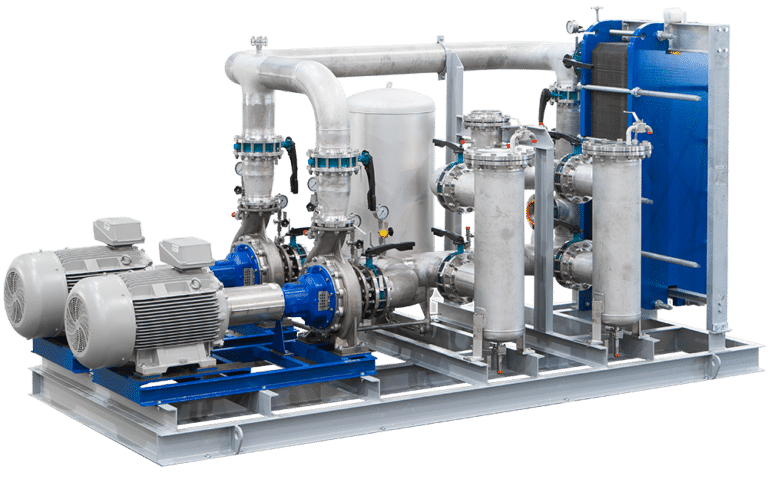
Overall, pump skid assemblies provide a compact, efficient, and reliable solution for fluid management in industrial applications. They offer ease of installation, streamlined maintenance, and optimized performance, making them a preferred choice for various industries requiring efficient fluid handling systems. Fig. 1 below shows a typical example of a pump skid used for water management.
Components of a Pump Skid
A pump skid typically incorporates several key components to facilitate fluid transfer, circulation, and control. While the specific components may vary based on the application and requirements, here are the fundamental elements commonly found in a pump skid:
- Pump: The pump is the primary component responsible for generating fluid flow. It can be a centrifugal pump, positive displacement pump, or another type, selected based on the specific application requirements such as flow rate, pressure, viscosity, and fluid properties.
- Motor: The motor provides the power necessary to drive the pump. It can be an electric motor, diesel engine, or any other suitable power source, depending on the application and site conditions.
- Piping and Valves: The pump skid includes an arrangement of piping and valves to facilitate the movement and control of fluids. Piping connects the pump inlet and outlet to the desired points of fluid transfer or circulation. Valves, such as gate valves, ball valves, or control valves, regulate the flow rate, pressure, and direction of the fluid within the system.
- Instrumentation: Various instrumentation devices are incorporated into the pump skid to monitor and control the fluid parameters. These may include flow meters, pressure gauges, temperature sensors, level sensors, and other instruments that provide real-time data for process monitoring and control.
- Control Systems: Pump skids often feature control systems, which can be simple or complex depending on the application. These systems provide automation and control capabilities, allowing operators to adjust and optimize the pump operation, monitor critical parameters, and respond to alarms or abnormal conditions.
- Base or Skid: The base or skid serves as the foundation for mounting and supporting all the components of the pump skid. It is designed to provide stability and structural integrity while facilitating ease of transport, installation, and maintenance.
- Safety Devices: Depending on the application and industry, pump skids may incorporate safety devices such as pressure relief valves, rupture discs, emergency shutdown systems, and other safety mechanisms to protect against overpressure, over-temperature, or other hazardous conditions.
- Electrical and Control Wiring: The pump skid includes electrical wiring to connect the motor, control systems, and instrumentation devices. These wiring connections enable power supply, control signal transmission, and communication between different components of the skid.
- Filters: Filters are used to remove impurities from the fluid before it enters the pump. This helps to protect the pump and to ensure that the fluid is clean.
- Pressure gauges: Pressure gauges are used to monitor the pressure of the fluid in the pump skid. This helps to ensure that the pump is operating within its safe operating limits.
- Accessories: Additional accessories may be included based on the specific requirements of the application. These can include strainers, dampeners, pressure regulators, heat exchangers, and other devices necessary for specific fluid conditioning or process needs.
In addition to these basic components, pump skids may also include other features such as insulation, vibration isolation, and weatherproofing. These features are typically added to protect the pump skid from harsh environmental conditions or to make it easier to transport.
Wide Range of Applications
Pump skid assemblies find application in diverse industries, owing to their versatility and adaptability. Here are some key areas where these assemblies are commonly utilized:
- Oil and Gas: Pump skid assemblies play a vital role in oil and gas exploration, production, and refining. They are used for well stimulation, water injection, pipeline transfer, and other critical processes.
- Chemical and Petrochemical: In the chemical and petrochemical industries, pump skid assemblies handle various fluids such as acids, solvents, and hazardous materials. They ensure precise metering, blending, and transfer while adhering to strict safety standards.
- Water and Wastewater: Pump skid assemblies are employed in water treatment plants, sewage systems, and desalination plants to facilitate water circulation, filtration, and transfer. These systems help maintain a consistent water supply and manage wastewater effectively.
- Power Generation: From conventional power plants to renewable energy installations, pump skid assemblies play a crucial role in cooling systems, condensate extraction, fuel transfer, and boiler feedwater applications.
- Pharmaceuticals: In pharmaceutical manufacturing, pump skid assemblies offer precise control and sterile fluid handling, supporting critical processes like ingredient mixing, liquid transfer, and batch formulation.
- Pulp and Paper: The pump skids in the pulp and paper industries are usually equipped with chemical metering and injection components.
Some other industries that utilize packaged pump skids are
- Petroleum
- Agriculture
- Food and beverage
- Brewing
Advantages of Pump Skid Assemblies
Pump skids offer several advantages over traditional pump installations, including:
Ease of installation:
Pump skids are typically pre-assembled and tested at the factory, which means that they can be quickly and easily installed on-site. This can save a significant amount of time and money, especially for complex pump systems.
Space Efficiency:
Pump skids are designed to be compact and space-efficient. By integrating all the necessary components onto a single skid, they eliminate the need for large equipment rooms or complex piping systems. This not only saves valuable floor space but also simplifies the layout and reduces the overall footprint of the fluid management system.
Portability:
Pump skids are typically designed to be portable, which makes them ideal for applications where the pump needs to be moved frequently. For example, pump skids are often used in construction projects where the pump needs to be moved from one location to another as the project progresses.
Flexibility:
Pump skids can be customized to meet the specific requirements of the application. This means that the pump, driver, piping, valves, and other components can be selected to optimize the performance of the system.
Safety:
Pump skids are typically designed to meet all applicable safety standards. This helps to ensure that the pump is safe to operate and that it will not pose a hazard to personnel or the environment.
Cost-effectiveness:
Pump skids can be a cost-effective solution for a variety of applications. The upfront cost of a pump skid may be higher than the cost of a traditional pump installation, but the savings in time and labor can offset the initial investment.
Enhanced Performance and Reliability:
Pump skids are carefully designed and engineered to ensure optimal performance and reliability. As all components are selected and integrated to work together cohesively, the risk of compatibility issues or performance limitations is minimized. The standardized design and quality control measures during manufacturing contribute to consistent performance, increased efficiency, and improved system reliability.
Ease of Maintenance and Serviceability:
Pump skids are designed with maintenance and serviceability in mind. With all the components mounted on a single skid, technicians have easy access to the entire system for inspection, troubleshooting, and repairs. This simplifies maintenance procedures, reduces downtime, and allows for efficient servicing of the equipment.
Automation and Control Capabilities:
Pump skids often incorporate advanced control systems and automation features. This allows for precise monitoring and control of fluid parameters, such as flow rates, pressures, and temperatures. Automated controls enable operators to optimize system performance, respond to changes in process conditions, and ensure consistent and accurate fluid management.
Compliance:
Pump skids are designed to adhere to industry safety standards and regulations. They often include built-in safety devices, such as pressure relief valves and emergency shutdown systems, to protect against overpressure or other hazardous conditions. By ensuring compliance with safety guidelines, pump skids contribute to a safer working environment.
Overall, pump skids offer a number of advantages over traditional pump installations. They are easy to install, portable, flexible, safe, and cost-effective. These advantages make pump skids a good choice for a variety of industrial applications.
Here are some specific examples of the advantages of pump skids in different applications:
- Water pumping: Pump skids are often used for water pumping applications, such as fire suppression, irrigation, and water treatment. The portability of pump skids makes them ideal for these applications, as the pumps can be easily moved from one location to another as needed.
- Chemical dispensing: Pump skids are also used for chemical dispensing applications, such as industrial cleaning and wastewater treatment. The flexibility of pump skids allows them to be customized to meet the specific requirements of the application, such as the type of chemical being dispensed and the flow rate required.
- Process metering: Pump skids are also used for process metering applications, such as oil and gas production and food and beverage processing. The accuracy and reliability of pump skids make them ideal for these applications, where precise control of the flow rate is critical.
If you are considering a pump installation for your industrial application, you should consider the advantages of pump skids. Pump skids can save you time, money, and hassle, and they can help you to meet your specific application requirements.
Common Industrial Pump Skid Packages
There are various types of pump skid packages available, designed to cater to different industrial applications and fluid management needs. Here are some common types of pump skid packages:
- Booster Pump Skids: Booster pump skids are used to increase the pressure or flow rate of fluids in a system. They are commonly employed in water distribution networks, building services, irrigation systems, and other applications where an additional boost in fluid pressure is required.
- Circulation Pump Skids: Circulation pump skids are designed to maintain the continuous flow of fluids within a closed-loop system. They are often used in HVAC systems, thermal oil circulation, heat exchangers, and other processes that require consistent fluid circulation and temperature control.
- Transfer Pump Skids: Transfer pump skids are utilized for transferring fluids from one location to another. They are commonly used in industries such as oil and gas, chemical processing, and water treatment plants, where the movement of fluids between tanks, vessels, or pipelines is necessary.
- Metering Pump Skids: Metering pump skids are employed for precise dosing or metering of fluids. They are commonly used in applications that require accurate and controlled addition of chemicals, additives, or ingredients. Industries such as water treatment, pharmaceuticals, and food and beverage often utilize metering pump skids for precise and controlled fluid dosing.
- Fire Pump Skids: Fire pump skids are specifically designed for fire protection systems. They provide a high-pressure water supply to fire sprinkler systems, hydrants, or foam suppression systems. Fire pump skids are critical in industrial facilities, commercial buildings, and other locations where fire safety is paramount.
- Chemical Injection Skids: Chemical injection skids are used for injecting precise amounts of chemicals into industrial processes. They are commonly employed in oil and gas production, refineries, and chemical plants for corrosion inhibition, scale prevention, and other chemical treatment applications.
- Wellhead Pump Skids: Wellhead pump skids are utilized in oil and gas operations to boost fluid flow from production wells. These skids are designed to handle the challenging conditions of wellhead environments and provide reliable pumping solutions for oil and gas extraction.
- Pulp and paper pump skids: These skids are used to pump fluids in the pulp and paper industry. They typically include a centrifugal pump, a driver, piping, valves, and a control system.
Selection of Pump Skid Packages
When choosing a pump skid package, it is important to consider the specific requirements of the application. The following factors should be considered:
- The type of fluid to be pumped: The type of fluid will determine the type of pump and driver that is needed.
- The flow rate and pressure requirements: The flow rate and pressure requirements will determine the size of the pump and driver.
- The environmental conditions: The environmental conditions will determine the type of materials that are used in the pump skid.
- The safety requirements: The safety requirements will determine the type of control system that is used.
- Application and Industry: Consider the specific application and industry requirements. Different industries have unique needs, such as oil and gas, chemical processing, water treatment, or pharmaceuticals. Understanding the specific industry standards, safety regulations, and operational demands will aid in choosing a pump skid package that aligns with those requirements.
- System Design and Integration: Assess the overall system design and integration needs. Determine whether additional components, such as valves, instrumentation, control systems, or filtration equipment, are required to ensure the pump skid package integrates seamlessly with the existing infrastructure and processes.
- Space and Site Constraints: Evaluate the available space and site constraints for installation. Consider the dimensions and footprint of the pump skid package to ensure it fits within the allocated space. Additionally, assess any specific site limitations, such as access restrictions or environmental conditions, that may impact the installation and operation of the skid package.
Conclusion
Pump skid assemblies have revolutionized fluid management in industrial applications. Their compact design, ease of installation, and maintenance advantages make them an attractive choice for various industries. These pre-engineered systems deliver enhanced efficiency, reliability, and automation capabilities. With a wide range of applications across industries, pump skid assemblies continue to streamline processes and contribute to the smooth operation of industrial facilities. By investing in these versatile solutions, businesses can ensure optimal performance and increase productivity in their fluid management operations.