Black steel pipes are an essential component in a variety of industrial and construction applications. In the industrial applications, the choice of materials can significantly impact the performance, durability, and aesthetics of a project. Among the myriad options available, black steel piping has emerged as a popular and compelling choice. These pipes, with their dark and matte appearance, offer more than just a striking visual appeal. In this article, we’ll explore the world of black steel pipes, exploring their characteristics, manufacturing process, diverse applications, and the advantages they bring to various industries. Towards the end, we will learn about the major differences between black steel and carbon steel pipes.
What are Black Steel Pipes?
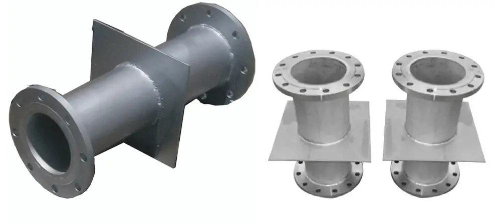
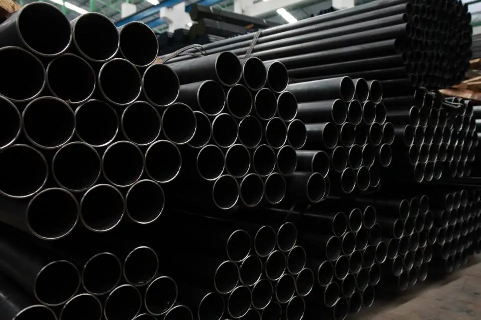
Black steel pipes are a type of steel pipes that have been subjected to a blackening process, giving them their characteristic dark appearance. These pipes are also known as black iron pipes or black malleable iron pipes. Unlike other steel pipes that have a shiny, silver-grey surface, black steel pipes have a dark and matte finish, which sets them apart in terms of aesthetics and applications. Fig. 1 below shows typical examples of black steel pipes.
Manufacturing of Black Steel Pipes
The manufacturing process of black steel pipes involves two primary methods:
Seamless Black Steel Pipes:
Seamless black steel pipes are produced by piercing a solid steel billet to create a hollow cylindrical shape. The absence of a welded seam makes them stronger and suitable for high-pressure applications.
Welded Black Steel Pipes:
Welded black steel pipes are made by bending and welding steel sheets or strips to form a cylindrical shape. They are a cost-effective alternative to seamless pipes and are commonly used for various industrial and structural applications.
The Blackening Process
After the pipes are formed, they go through a blackening process to obtain their dark appearance. The blackening treatment involves coating the surface of the steel pipes with a black oxide layer. The most common method used is hot-dip galvanization or hot-dip blackening.
In hot-dip galvanization, the steel pipes are immersed in a bath of molten zinc, which reacts with the surface of the steel, forming a protective zinc-iron alloy coating. The resulting pipes have a dark, matte-black appearance.
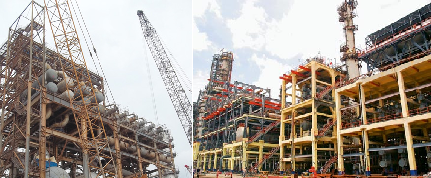
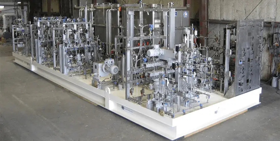
Applications of Black Steel Pipes
Black steel pipes find wide-ranging applications in various industries due to their unique properties and appearance:
- Plumbing and Water Supply: Black steel pipes are commonly used for plumbing and water supply lines, especially in residential and commercial buildings. They are well-suited for transporting potable water and other non-corrosive fluids.
- Natural Gas Distribution: Black steel pipes are widely used for natural gas distribution systems due to their durability and corrosion resistance.
- Fire Sprinkler Systems: Black steel pipes are often used in fire sprinkler systems, where their high strength and ability to withstand high pressure and heat make them suitable for fire protection applications.
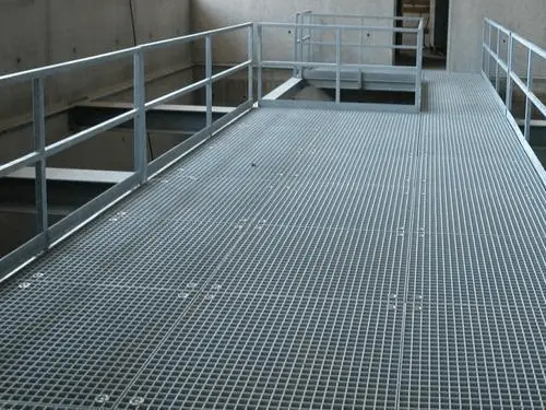
- Industrial and Structural Applications: Black steel pipes are employed in various industrial and structural applications, including scaffolding, fencing, handrails, and support structures.
- Oil and Gas Transmission: In certain cases, black steel pipes are used for the transportation of crude oil, petroleum products, and natural gas.
Advantages of Black Steel Pipes
The main advantages of black steel pipes are
- Corrosion Resistance: The black oxide layer formed during the blackening process provides a protective barrier, reducing the risk of corrosion and rusting.
- Strength and Durability: Black steel pipes are strong and durable, making them suitable for high-pressure applications and structural purposes.
- Cost-Effectiveness: Compared to some other materials, black steel pipes offer a cost-effective solution for various applications.
- Aesthetics: The dark and matte finish of black steel pipes adds a touch of elegance and complements different architectural styles.
- Versatility: From plumbing systems to industrial projects, black steel pipes can adapt to a wide array of applications, making them a versatile choice across various industries.
Black Steel Pipe Fittings
Black steel pipe fittings are connectors and components made from black steel that are designed to join or change the direction of black steel pipes. These fittings are essential in plumbing, industrial, and construction applications where black steel pipes are used. The fittings are coated with the same black oxide layer as the pipes, ensuring a consistent appearance throughout the system. Here are some common types of black steel pipe fittings:
- Black Steel Elbow: Elbows are fittings used to change the direction of the pipeline. Black steel elbows are available in various angles, such as 45 degrees and 90 degrees, to facilitate changes in the pipeline route.
- Black Steel Tee: Tees have a “T” shape and are used to join three pipelines at a 90-degree angle. They are commonly used in branching connections.
- Black Steel Coupling: Couplings are used to join two pipes together in a straight line. They come in different lengths and diameters to accommodate various pipe sizes.
- Black Steel Union: Unions are a type of coupling that allows for easy disconnection of pipes for maintenance or repairs. They consist of three parts: a nut, a female end, and a male end.
- Black Steel Bushing: Bushings are used to reduce the size of a pipe thread, fitting inside a larger pipe to create a smaller threaded connection.
- Black Steel Cap: Caps are used to close the end of a pipe. They provide a seal and prevent debris or liquids from entering the pipe.
- Black Steel Nipple: Nipples are short pieces of pipe with male threads on both ends. They are used to extend or connect fittings together.
- Black Steel Cross: Cross fittings have a “plus” shape and are used to join four pipes together at right angles.
- Black Steel Reducer: Reducers are used to connect pipes of different diameters, allowing for a smooth transition between the two sizes.
- Black Steel Flange: Flanges are flat, circular fittings used to connect pipes to valves, pumps, or other equipment. They provide an easy way to disassemble and reassemble a system.
Differences between Black Steel Pipes and Carbon Steel Pipes
Black steel pipes and carbon steel pipes are often confused due to their similar appearance and material composition. However, there are some important differences between the two types of pipes that can affect their applications and performance. Let’s explore the major differences between black steel pipes and carbon steel pipes:
1. Surface Finish:
- Black Steel Pipes: Black steel pipes have a dark, matte black finish due to the blackening process they undergo. This blackening is achieved by applying a black oxide layer to the surface of regular steel pipes.
- Carbon Steel Pipes: Carbon steel pipes, in their raw state, have a silvery-grey appearance. They may or may not have a protective coating, depending on their intended use and the manufacturer’s specifications.
2. Corrosion Resistance:
- Black Steel Pipes: Black steel pipes have some degree of corrosion resistance due to the black oxide coating. However, this coating is not as effective as other protective coatings, such as galvanization.
- Carbon Steel Pipes: Carbon steel pipes, especially when untreated, are more susceptible to corrosion. To enhance their corrosion resistance, carbon steel pipes are often galvanized or coated with other protective materials.
3. Manufacturing Process:
- Black Steel Pipes: Black steel pipes can be made through either the seamless or welded manufacturing process, just like carbon steel pipes. The blackening process is applied after the pipes are formed.
- Carbon Steel Pipes: Carbon steel pipes are also available in seamless and welded variations. The choice between the two depends on the application requirements and cost considerations.
4. Applications:
- Black Steel Pipes: Black steel pipes find applications in plumbing, gas distribution, fire protection systems, and structural supports. They are commonly used for non-corrosive fluids and gases.
- Carbon Steel Pipes: Carbon steel pipes have a broader range of applications due to their versatility. They are used in industries such as oil and gas, petrochemicals, power generation, automotive, construction, and more. Depending on the specific requirements, carbon steel pipes can be used for transporting various liquids, gases, and abrasive materials.
5. Cost:
- Black Steel Pipes: Black steel pipes may have a slightly higher cost compared to untreated carbon steel pipes due to the additional blackening process.
- Carbon Steel Pipes: Untreated carbon steel pipes are generally more affordable than black steel pipes. However, if carbon steel pipes are galvanized or coated for corrosion resistance, the cost may increase.
6. Durability:
- Black Steel Pipes: Black steel pipes are durable and can withstand normal operating conditions. However, the black oxide coating may wear off over time, potentially affecting their long-term corrosion resistance.
- Carbon Steel Pipes: Carbon steel pipes, especially when galvanized or coated, offer excellent durability and resistance to various environmental factors.
In summary, the main difference between black steel pipes and carbon steel pipes lies in the blackening process and the resulting surface finish. Black steel pipes have a dark, matte appearance due to the black oxide coating, while carbon steel pipes have a silvery-grey appearance. Additionally, carbon steel pipes, especially when galvanized or coated, offer superior corrosion resistance and broader applications compared to black steel pipes. The choice between the two types of pipes depends on the specific requirements of the intended application and the budget constraints. The above differences are provided below in a tabular format for easy comparison.
| Feature | Black Steel Pipes | Carbon Steel Pipes |
|---|---|---|
| Surface Finish | Dark, matte black due to the blackening process. | Silvery-grey appearance (may be coated or untreated). |
| Corrosion Resistance | Some degree of corrosion resistance due to the black oxide coating. | Susceptible to corrosion (may be galvanized or coated). |
| Manufacturing Process | Can be made through a seamless or welded process, with blackening applied after formation. | Can be made through a seamless or welded process, and may or may not be coated. |
| Applications | Plumbing, gas distribution, fire protection, and structural supports for non-corrosive fluids and gases. | Wide range of applications, including oil and gas, petrochemicals, construction, etc. |
| Cost | Slightly higher cost due to the blackening process. | Generally more affordable (coating may affect cost). |
| Weldability | A little difficult to weld. | Welding carbon steel pipes are easier. |
| Hardness | More hard and a little brittle. | Hardness is less and more ductile. |
| Durability | Durable, but the black oxide coating may wear off over time. | Durable, especially when galvanized or coated. |
Conclusion
Black steel pipes are a popular choice for various applications, offering a combination of durability, corrosion resistance, and a unique aesthetic appeal. Whether used for plumbing, gas distribution, structural support, or industrial purposes, black steel pipes continue to be an essential component in modern infrastructure and construction projects.
Online Courses on Piping Design and Engineering
If you wish to dig deeper and learn more about elements of piping design and engineering then the below-mentioned online courses will help you to do so:
- Designing Piping Systems: Pipe Fittings Flanges Valves
- Piping Isometrics demystified through practical examples
- Flow of fluids through piping systems , valves and pumps
- The Complete Course on Piping Components for Oil&Gas Career
- Piping Design Engineering & Piping Isometrics Masterclass
- PG Diploma in Piping Design Engineering
- Click here for other relevant piping engineering courses