Pressure vessels serve as vital components in various industries, safeguarding gases and liquids under high pressure. The manufacturing process of these vessels is a careful blend of art and science, ensuring structural integrity, material compatibility, and adherence to safety standards. In this article, we delve into the fascinating world of pressure vessel manufacturing, exploring the key steps involved and the critical considerations that go into producing these essential engineering marvels.
What is Pressure Vessel Manufacturing?
Pressure vessel manufacturing refers to the process of designing, fabricating, and constructing containers that are specifically designed to hold gases or liquids at pressures significantly different from ambient pressure. These vessels are crucial components in various industries, ranging from oil and gas, petrochemicals, power generation, aerospace, and pharmaceuticals to water treatment, food processing, and many others.
Stages of Pressure Vessel Manufacturing
There are various types of pressure vessels used in chemical, petrochemical, and power industries. The manufacturing steps for each type of pressure vessel usually differ significantly. The major steps that are followed while pressure vessels manufacturing are as follows:
Design and Engineering:
The manufacturing process of pressure vessels begins with meticulous design and engineering. Experienced engineers work closely with clients to understand their specific requirements, including operating conditions, material choices, pressure ratings, and applicable codes and standards (e.g., ASME BPVC, PED, or others). Computer-aided design (CAD) and simulation tools are employed to create detailed 3D models, facilitating thorough analysis and optimization of the vessel’s geometry and stress distribution.
Material Selection:
Selecting the appropriate material is crucial for the vessel’s performance and longevity. Engineers consider factors such as fluid properties, temperature, pressure, corrosion resistance, and cost-effectiveness when choosing materials. Commonly used materials include carbon steel, stainless steel, alloy steels, aluminum, and various high-performance alloys.
Cutting and Forming:
Once the design is finalized, the pressure vessel fabrication process commences with cutting and forming the metal sheets or plates. Advanced cutting techniques like plasma cutting, laser cutting, or waterjet cutting are used to achieve precise shapes. The plates are then shaped and formed using rolling machines, presses, or hydraulic equipment to create the vessel’s desired configuration.
Welding and Joining:
Welding is a critical aspect of pressure vessel manufacturing. Skilled welders use various welding processes, such as submerged arc welding (SAW), gas tungsten arc welding (GTAW), and shielded metal arc welding (SMAW), to join the components together. The welds must be of high quality, meeting stringent non-destructive testing (NDT) requirements to ensure the vessel’s structural integrity.
Heat Treatment:
In certain cases, heat treatment is employed to improve the material properties and relieve residual stresses. Post-weld heat treatment (PWHT) is often used to reduce the risk of cracking and enhance the weld’s mechanical properties.
Machining and Finishing:
After welding and heat treatment, the pressure vessel undergoes machining to achieve precise dimensions and smooth surfaces. This step ensures that all openings, nozzles, and flanges are accurately aligned for proper installation and operation. Surface finishing and painting may also be applied to protect against corrosion and enhance aesthetics.
Inspection and Testing:
Comprehensive inspection and testing are fundamental to ensure the pressure vessel’s safety and compliance with standards. Radiographic testing (RT), ultrasonic testing (UT), dye penetrant testing (PT), and magnetic particle testing (MT) are some of the NDT methods used to detect defects. Pressure testing is conducted to evaluate the vessel’s integrity under high-pressure conditions.
Certification and Documentation:
Once the vessel successfully passes all inspections and tests, it is certified by authorized agencies, confirming its compliance with the applicable codes and standards. Detailed documentation, including material certificates, fabrication records, inspection reports, and test results, is prepared to maintain a traceable record of the vessel’s manufacturing process.
Pressure Vessels Manufacturers
There are a large number of companies that manufacture pressure vessels and have a solid reputation in the industry. They have supplied pressure vessels for various applications, including power plants, petrochemicals, refineries, and industrial processes. Some of the reputed pressure vessel manufacturers are:
Babcock & Wilcox (B&W) – United States
Doosan Heavy Industries & Construction – South Korea
Mitsubishi Hitachi Power Systems (MHPS) – Japan
Larsen & Toubro (L&T) – India
Bharat Heavy Electricals Limited (BHEL) – India
Samsung Heavy Industries – South Korea
Mitsubishi Heavy Industries (MHI) – Japan
IHI Corporation – Japan
General Electric (GE) – United States
Amec Foster Wheeler (now part of Wood Group) – United Kingdom
Video Tutorial of Pressure Vessel Manufacturing
The following video shows the steps of pressure vessel manufacturing in a very simple and handy way:
Pressure Vessel Manufacturing Process Steps
Conclusion
The manufacturing of pressure vessels is a complex and highly regulated process, demanding a blend of engineering expertise, skilled craftsmanship, and unwavering commitment to safety and quality. These vessels play a pivotal role in ensuring the smooth functioning of various industries, from chemical plants and refineries to power generation and aerospace. By adhering to stringent design, fabrication, and inspection practices, manufacturers produce pressure vessels that not only meet the demands of modern engineering but also ensure the safety and well-being of people and the environment.
Online Course on Pressure Vessels
If you wish to learn more about Pressure Vessels, their design, fabrication, installation, etc in depth, then the following online courses will surely help you:
Pressure vessels play a crucial role in various industries. They help to process, store, or transport gases and liquids under high pressure. These vessels are designed to withstand internal or external pressure and are used in applications ranging from chemical plants and oil refineries to nuclear power plants and aerospace engineering. Heat exchangers, distillation towers, separators, reactors, reboilers, knock-out drums, scrubbers, dryers, coalescers, etc are some typical examples of pressure vessels. In this article, we will explore the different types of pressure vessels, their selection, and specific applications.
What is a Pressure Vessel?
A pressure vessel can be defined as a container designed to hold gases, vapors, liquids, or two-phase fluids at a pressure substantially different from the ambient pressure, and equipped with provisions for the introduction or removal of heat from the container. The pressure differential is dangerous, and there may be a risk of bursting if not properly designed, fabricated, installed, and maintained. Pressure vessels consist of some of the important parts like shell, head, nozzle, saddles, skirts, etc.
The ASME Boiler and Pressure Vessel Code provides rules and guidelines for the design, construction, inspection, testing, and certification of pressure vessels to ensure their safe operation under various pressure and temperature conditions. This code is widely recognized and followed by manufacturers, operators, and regulators worldwide to ensure the integrity and safety of pressure vessels used in various industries.
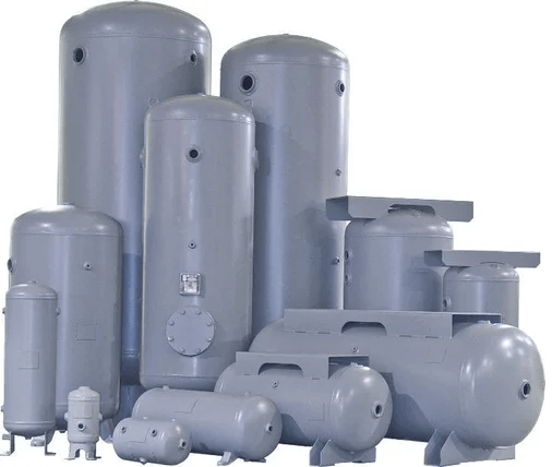
Types of Pressure Vessels
Pressure Vessels can be categorized based on various parameters as given below:
Pressure Vessel Types Based on Shape
Types of Pressure Vessels Based on Purpose
Classification of Pressure Vessels Based on Construction
Pressure Vessel Classification Based on Orientation/Positioning
Types of Pressure Vessels Depending on Mounting
Pressure Vessel Types Depending on the Material of Construction
Types of Pressure Vessels based on Method of Heating
A. Classification based on Shape
Considering the shapes, there are four specific types of pressure vessels as mentioned below:
Cylindrical Pressure Vessels
Spherical Pressure Vessels, and
Rectangular Pressure Vessels
Conical Pressure Vessels
(a) Cylindrical Pressure Vessels:
Cylindrical pressure vessels are one of the most common types. They have a cylindrical shape with flat or dished ends, offering a simple and effective design for containing fluids under pressure. These vessels are used in applications such as storage tanks, air receivers, and hydraulic accumulators.
(b) Spherical Pressure Vessels:
Spherical pressure vessels have a spherical shape, offering excellent pressure distribution and strength. The uniform distribution of stresses allows them to handle higher pressures compared to other shapes. Spherical vessels are typically used in industries dealing with high-pressure gases like LPG storage, petrochemicals, and aerospace.
(c) Rectangular Pressure Vessels:
Rectangular pressure vessels are less common but find their use in specific applications, such as storing compressed gases or liquids in confined spaces. Their design allows for integration into limited spaces where cylindrical or spherical vessels would be impractical.
(d) Conical Pressure Vessels:
A conical pressure vessel is a type of pressure vessel that has a conical shape, with one end resembling a cone. These vessels are commonly used in industries such as food processing, pharmaceuticals, and chemical manufacturing. The conical shape allows for efficient mixing and blending of substances and is often used in processes where controlled agitation, heating, or cooling is required. The conical design promotes the circulation of materials inside the vessel, making it suitable for applications where homogenization and uniform temperature distribution are essential.
B. Classification based on Purpose:
Depending on the specific application purpose, there are four types of pressure vessels that are found to be widely used for industrial applications. They are:
Storage Vessels
Heat Exchangers
Reactors, and
Distillation Columns
(a) Storage Vessels:
These pressure vessels are primarily used for storing liquids or gases at a specified pressure. Storage vessels often serve as reservoirs for various industries, including petrochemicals, pharmaceuticals, and water treatment plants.
(b) Heat Exchangers:
Heat exchangers are pressure vessels designed to facilitate heat transfer between two fluids at different temperatures. They play a crucial role in applications like power generation, refrigeration, and chemical processing.
(c) Reactors:
Reactors are pressure vessels employed in chemical and petrochemical industries to facilitate chemical reactions under controlled conditions. They can be used for processes like polymerization, hydrogenation, and synthesis.
(d) Distillation Columns:
Distillation columns, a type of pressure vessel, are used for separating components in a liquid mixture based on their boiling points. They are essential in the production of petroleum products, alcoholic beverages, and other chemicals.
C. Classification based on Construction:
As per construction, three pressure vessel types are popular in industries. They are:
Welded Pressure Vessels
Forged Pressure Vessels, and
Brazed Pressure Vessels
Cast Pressure Vessels
Riveted Pressure Vessels
(a) Welded Pressure Vessels:
Welded pressure vessels are constructed by welding together different sections of metal. They are commonly used in applications requiring low to medium pressure and are cost-effective for manufacturing.
(b) Forged Pressure Vessels:
Forged pressure vessels are made from a single piece of metal that is shaped and compressed under high pressure. This manufacturing process provides excellent strength and resistance, making them suitable for high-pressure applications.
(c) Brazed Pressure Vessels:
Brazed pressure vessels are assembled by joining metal parts using brazing techniques. They are often used for applications involving high temperatures and pressures, such as air conditioning and refrigeration.
(d) Cast Pressure Vessel
A cast pressure vessel is a pressure vessel that is manufactured by casting, a process where molten metal is poured into a mold to achieve the desired shape. Cast pressure vessels are typically made from materials like cast iron, cast steel, or other suitable alloys.
(e) Riveted Pressure Vessel
A riveted pressure vessel is a type of pressure vessel used to contain fluids or gases under pressure, and it is constructed by joining two or more metal plates or sections together using rivets. Rivets are mechanical fasteners that are inserted through holes in the plates and then deformed or headed on both ends to secure the plates tightly. Riveted pressure vessels were commonly used in the past but have largely been replaced by welded pressure vessels due to advancements in welding technology. These vessels are characterized by the visible rows of rivet heads on their exteriors.
D. Classification Based on Positioning/Orientation:
Pressure vessels come in various configurations, and one of the primary classifications is based on their positioning. Pressure vessels can be categorized as either horizontal or vertical, depending on the orientation of the vessel with respect to the ground. Each orientation offers distinct advantages and is chosen based on specific application requirements and space constraints.
Horizontal Pressure Vessels:
Horizontal pressure vessels are cylindrical tanks laid horizontally, with their length extending parallel to the ground. They typically have dished ends at both sides, providing structural stability and facilitating better stress distribution. The horizontal orientation allows for an even distribution of weight along the vessel’s length.
Typical Applications:
Transportable Storage: Horizontal vessels are commonly used for transporting liquids or gases from one location to another. Examples include tanker trucks used for transporting liquefied gases or liquid chemicals.
Compact Space Utilization: In applications where space is limited, such as onboard ships or in small processing plants, horizontal vessels prove advantageous as they can be placed under or alongside equipment efficiently.
Vapor-Liquid Separators: Horizontal pressure vessels are also used as vapor-liquid separators to remove entrained liquid droplets from gas streams in various processes.
Horizontal vessels are preferred when:
Space is limited, and a low-profile design is necessary.
Transportability is essential for moving liquids or gases between locations.
The vessel needs to function as a vapor-liquid separator in gas processing.
Types of Pressure Vessels-Horizontal vs Vertical
Vertical Pressure Vessels:
Vertical pressure vessels, as the name suggests, stand upright with their height perpendicular to the ground. They often have a cylindrical or spherical shape and can have either flat or dished ends. The vertical orientation allows for better utilization of vertical space, making them suitable for taller installations.
Typical Applications:
Storage Vessels: Vertical pressure vessels are widely used as storage tanks in industries such as petrochemicals, oil and gas, and water treatment. Their upright design minimizes the footprint and optimizes storage capacity.
Boiler Systems: Many industrial boiler systems utilize vertical pressure vessels to generate steam for power generation or heating applications.
Compressed Air Receivers: In pneumatic systems, vertical pressure vessels are employed as compressed air receivers to store pressurized air, ensuring a steady supply during peak demand.
Vertical vessels are preferred when:
Vertical space is available and needs to be optimized.
Higher storage capacities are required while minimizing the horizontal footprint.
The vessel will be utilized as a part of a taller system, such as in boiler installations.
E. Pressure Vessel Types Depending on Mounting/Supporting
Based on how the pressure vessel is mounted or supported there are three categories of pressure vessels.
Skirt Mounted Pressure Vessels: These are mainly vertical pressure vessels and they are supported by a skirt at the bottom of the vessel.
Saddle Mounted Pressure Vessel: Most horizontal pressure vessels are saddle-mounted. Typical examples are shell and tube heat exchangers.
Leg-Supported Pressure Vessels: Some of the vertical pressure vessels are found to be leg-supported.
Lug-Supported Pressure Vessels: These types of pressure vessels are mounted on lug supports which are basically plates with holes.
F. Pressure Vessel Types Depending on the Material of Construction
Based on the base material of construction, pressure vessels are classified as follows:
Metallic Pressure Vessels
Ferrous Pressure Vessels
Carbon Steel Vessels
Stainless Steel Vessels
Alloy Steel Vessels
Cast Iron Pressure Vessels
Non-Ferrous Pressure Vessels
Aluminum Pressure Vessels
Non-metallic Pressure Vessel
Plastic Pressure Vessels
Composite Metal Pressure Vessels
G. According to the Method of Heating
Depending on the type of heating, there are two types of pressure vessels as mentioned below:
Sometimes, pressure vessels are also classified based on the shell thickness. They are:
Thick-walled Pressure Vessel, and
Thin-walled Pressure Vessels
Selection of Pressure Vessels
The selection of pressure vessel types depends on several factors, including the specific application requirements, operating conditions, material compatibility, and available space. Here are some key considerations to help guide the selection process:
Application and Purpose: Identify the primary purpose of the pressure vessel. Is it for storage, transportation, heat exchange, chemical reaction, or another specialized function? Each type of pressure vessel is designed to fulfill specific roles, so understanding the application is essential.
Pressure and Temperature: Determine the operating pressure and temperature requirements. Different pressure vessels are designed to withstand various pressure levels and temperature ranges. Choose a vessel that can safely handle the intended pressure and temperature conditions.
Material of Construction: Consider the compatibility of the vessel’s material with the fluid or gas it will contain. Materials must be resistant to corrosion, stress, and fatigue. Common materials include carbon steel, stainless steel, aluminum, and various alloys.
Space Constraints: Evaluate the available space for installation. Horizontal vessels may be suitable when space is limited, while vertical vessels can be more efficient in maximizing storage capacity within a restricted footprint.
Transportability: If the vessel needs to be transported between locations, consider factors like weight, size, and the need for mobility. Horizontal vessels are often preferred for transportable applications.
Codes and Standards: Adhere to relevant codes and standards, such as the ASME Boiler and Pressure Vessel Code or other international regulations, to ensure compliance with safety guidelines and legal requirements.
Maintenance and Inspection: Consider ease of maintenance and inspection. Some vessel designs may facilitate easier access for inspection and repairs, which can contribute to the longevity and safe operation of the vessel.
Cost and Life-Cycle Considerations: Evaluate the initial cost, ongoing maintenance expenses, and the expected service life of the pressure vessel. Choose a vessel that balances cost-effectiveness with long-term reliability.
Examples of Pressure Vessel Types for Different Applications:
Storage Vessels: Vertical cylindrical pressure vessels are often used for bulk storage of liquids and gases, such as in oil refineries, petrochemical plants, and water treatment facilities.
Heat Exchangers: Shell and tube heat exchangers are widely used for transferring heat between two fluids at different temperatures.
Reactors: Depending on the process requirements, reactors can be cylindrical, spherical, or other specialized shapes designed for specific chemical reactions.
Compressed Air Receivers: Vertical pressure vessels with dished ends are commonly used as compressed air receivers in industrial pneumatic systems.
Transportable Tanks: For transporting liquefied gases or liquids, horizontal cylindrical pressure vessels are commonly used, often mounted on transport vehicles.
Video Tutorial on Pressure Vessel Fundamentals
The following video provides a very nice overview of the fundamentals of pressure vessels that one should know:
Pressure Vessel Fundamentals
Online Course on Pressure Vessels
If you wish to learn more about Pressure Vessels, their design, fabrication, installation, etc in depth, then the following online courses will surely help you:
In the world of structural and mechanical engineering, choosing the right materials is crucial for ensuring durability, reliability, and safety. One widely recognized and extensively used material in the construction industry is ASTM A53. In this blog article, we will delve into the characteristics, strengths, and applications of ASTM A53, shedding light on why it is a popular choice for a wide range of projects.
What is ASTM A53?
ASTM A53 is a specification developed by the American Society for Testing and Materials (ASTM). It sets the standard for seamless and welded steel pipes used in various applications. The specification covers different grades, types, and dimensions of pipes, catering to diverse industrial requirements. This specification covers seamless and welded black and hot-dipped galvanized steel pipes of size NPS 1⁄8 to NPS 26 (DN 6 to DN 650).
Types and Applications of ASTM A53
ASTM A53 pipes are mainly used in low-critical applications like plumbing systems, water supply systems, fire sprinkler systems, HVAC systems, etc. They are also found to be widely used in structural applications.
ASTM A53 covers three types of pipes as listed below:
Type F—Furnace-butt-welded, continuous welded Grade A,
Type E—Electric-resistance-welded, Grades A and B, and
Type S—Seamless, Grades A and B.
Seamless A53 Pipes:
ASTM A53 Type S seamless pipes are available in two grades; Grade A and Grade B. Type S ASTM A53 pipes are produced by the extrusion method.
Welded A53 Pipes:
As mentioned above there are two types of welded A53 pipes; Type E and Type F. Type E has two grades-Grade A and Grade B; while Type F has only Grade A.
Type E A53 pipes are Electric resistance welded (ERW) pipes designed for general mechanical and structural applications. Type F A53 pipes are Furnace-welded pipes commonly used in non-pressure plumbing applications, such as drain, waste, and vent systems.
The steel for both seamless and welded pipes is made by one or more of the following processes: open-hearth, electric furnace, or basic oxygen.
Chemical Composition of ASTM A53/A53M Materials
The chemical composition of ASTM A53 material is provided in Table 1.
Type
Grade
Carbon
Manganese
Phosphorus
Sulfur
Copper
Nickel
Chromium
Molybdenum
Vanadium
Type S (seamless pipe)
Grade A
0.25
0.95
0.05
0.045
0.40
0.40
0.40
0.15
0.08
Type S (seamless pipe)
Grade B
0.30
1.20
0.05
0.045
0.40
0.40
0.40
0.15
0.08
Type E (electric-resistance-welded)
Grade A
0.25
0.95
0.05
0.045
0.40
0.40
0.40
0.15
0.08
Type E (electric-resistance-welded)
Grade B
0.30
1.20
0.05
0.045
0.40
0.40
0.40
0.15
0.08
Type F (furnace-welded pipe)
Grade A
0.30
1.20
0.05
0.045
0.40
0.40
0.40
0.15
0.08
Table 1: ASTM A53 Chemical Composition
Advantages of ASTM A53 Pipes
Strength and Durability:
ASTM A53 pipes are manufactured from carbon steel, which imparts excellent strength (Tensile Strength for Grade A: 330 MPa, for Grade B: 415 MPa) and durability. Carbon steel exhibits high tensile strength, making it suitable for applications that require resistance to high pressure and mechanical stress.
Versatility:
ASTM A53 pipes are available in various types and grades. These grades differ in terms of chemical composition and mechanical properties, allowing engineers to select the most suitable grade based on specific project requirements.
Corrosion Resistance:
ASTM A53 pipes can be galvanized to enhance their corrosion resistance. Galvanization involves coating the pipes with a layer of zinc, providing an additional protective barrier against rust and corrosion, particularly in outdoor or high-moisture environments.
Cost-Effective:
ASTM A53 pipes offer an excellent balance between performance and cost. The availability of different grades and sizes ensures that there is a suitable option for a wide range of budgetary constraints without compromising on quality.
Compliance and Quality Control:
ASTM A53 is a widely recognized and respected standard in the steel industry. To ensure compliance and quality control, manufacturers adhere to strict guidelines and conduct various tests, including dimensional inspection, visual examination, hydrostatic testing, and non-destructive testing.
ASTM A53 Pipe Specification
Specifying ASTM A53 pipes involves providing detailed information about the specific requirements for the pipes you need. This includes specifying the type, grade, size, length, quantity, and any additional requirements or tests. Below are the key steps to properly specify ASTM A53 pipes:
Type and Grade:
Determine the type of pipe required based on the intended application:
Type S: Seamless pipe, suitable for high-temperature and pressure applications.
Type E: Electric-resistance-welded (ERW) pipe, suitable for general mechanical and structural applications.
Type F: Furnace-welded pipe, commonly used in non-pressure plumbing applications.
Select the appropriate grade (A or B) based on the mechanical and chemical properties required for your application. Refer to the provided chemical compositions to make an informed decision.
Size:
Specify the nominal pipe size (NPS) which represents the approximate inside diameter of the pipe. This is typically expressed in inches. For example, NPS 2 refers to a pipe with an approximate inside diameter of 2 inches.
Length:
Specify the required length of the pipes. They are available in standard lengths or custom lengths based on requirements.
Quantity:
Indicate the total quantity of pipes needed for your project.
Coating or Finish:
Specify if any special coating or finish is required. For example, you may need galvanized pipes to enhance corrosion resistance.
End Finish:
Specify the type of end finish required, such as plain ends, threaded ends, or beveled ends. Threaded ends are commonly used for connecting pipes, while beveled ends are beneficial for welding purposes.
Testing and Inspection:
Outline any specific testing or inspection requirements. ASTM A53 pipes undergo various tests, including hydrostatic testing, non-destructive testing, and visual inspection. You can request additional tests to ensure compliance with specific project standards.
Standards and Certifications:
Clearly state the ASTM A53 specification and edition to which the pipes must conform. Additionally, specify any other relevant standards or certifications that the pipes must meet.
Special Requirements:
If there are any special requirements or modifications needed for the pipes, such as specific tolerances, marking, or packaging, make sure to include them in the specification.
Example Specification:
Here’s an example of how you could specify ASTM A53 pipes:
Always communicate your specifications clearly with the pipe supplier or manufacturer to ensure you receive the correct pipes that meet your project requirements.
ASTM A53 Sch 40 Pipe Dimensions
The pipe dimensions for ASTM A53 Sch 40 pipes are given in Table 2 below:
ASTM A53 Grades A and B Pipe Schedule 40 Dimensions
NPS Designator
DN Designator
Outside Diameter
Inside Diameter
Wall Thickness
Nominal Weight (Mass) per unit Length
(mm)
(mm)
(mm)
Plain End (kg/m)
Threads & Couplings (kg/m
1/8″
6
10.3
6.8
1.73
0.37
0.37
1/4″
8
13.7
9.2
2.24
0.63
0.63
3/8″
10
17.1
12.5
2.31
0.84
0.84
1/2″
15
21.3
15.8
2.77
1.27
1.27
3/4″
20
26.7
20.9
2.87
1.69
1.69
1″
25
33.4
26.6
3.38
2.5
2.5
1-1/4″
32
42.2
35.1
3.56
3.39
3.4
1-1/2″
40
48.3
40.9
3.68
4.05
4.04
2″
50
60.3
52.5
3.91
5.44
5.46
2-1/2″
65
73
62.7
5.16
8.63
8.67
3″
80
88.9
77.9
5.49
11.29
11.35
3-1/2″
90
101.6
90.1
5.74
13.57
13.71
4″
100
114.3
102.3
6.02
16.07
16.23
5″
125
141.3
158.2
6.55
21.77
22.07
6″
150
168.3
154.1
7.11
28.26
28.58
8″
200
219.1
202.7
8.18
42.55
43.73
10″
250
273
254.5
9.27
60.29
63.36
12″
300
323.8
304.8
9.52
73.78
76.21
Table 2: ASTM A53 Sch 40 Pipe Dimensions
ASTM A53 vs ASTM A106: Differences
Below is a tabular format highlighting the major differences between ASTM A53 and ASTM A106 pipes:
Aspect
ASTM A53
ASTM A106
Scope
Covers seamless and welded black and hot-dipped galvanized steel pipes
Covers seamless carbon steel pipes for high-temperature service
Grades
Grade A, Grade B
Grade A, Grade B, Grade C
Chemical Composition
Limited to carbon (max 0.30% for Grade B)
Carbon and alloy elements allowed (no specific limits)
Manufacturing Process
Seamless and welded
Seamless only
Applications
Plumbing, HVAC, low-pressure steam, water, gas lines
Power plants, refineries, boilers, heat exchangers
Surface Finish
Can be hot-dipped galvanized
Typically not galvanized
Tolerances
Wall thickness and outside diameter tolerances are less strict
Wall thickness and outside diameter tolerances are stricter
Table 3: Differences between ASTM A53 and ASTM A106 Pipe Materials
Conclusion
ASTM A53 stands as a testament to the reliability and versatility of carbon steel pipes. Its robustness, corrosion resistance, and cost-effectiveness make it a popular choice for numerous applications, ranging from industrial processes to plumbing systems. By adhering to the specifications outlined in ASTM A53, engineers and manufacturers can achieve optimal performance and safety in their projects.
Pipe Support Brackets: Types, Installation, and Importance
Pipe support brackets play a crucial role in various industries and infrastructure projects. These brackets, also known as pipe hangers or pipe clamps, are essential components for supporting and securing pipes in a wide range of applications. From residential plumbing systems to large-scale industrial projects, understanding pipe support brackets is vital for ensuring the safety, stability, and longevity of the piping infrastructure. This article aims to provide a comprehensive overview of pipe support brackets, including their types, installation, and importance.
What is a Bracket in Piping?
In piping, a bracket, also known as a pipe support bracket is a mechanical device used to support, secure, and position pipes in a piping system. These brackets are essential components that play a crucial role in maintaining the integrity and stability of the entire piping infrastructure. Brackets are designed to hold pipes in place, prevent excessive movement, and distribute the weight of the pipes and their contents to the surrounding structure.
The primary purpose of using brackets in piping is to ensure that the pipes remain in their designated positions and maintain proper alignment, even under various operating conditions. Piping systems can be subject to thermal expansion and contraction, varying fluid pressures, and dynamic forces, which could lead to stress on the pipes. Brackets help mitigate these stresses and maintain the overall functionality and safety of the system.
They can be installed as loose pipe brackets or fixed pipe brackets. A loose pipe bracket allows axial movement of the pipe. The axial thermal movement is allowed during operational changes when loose pipe brackets are used. The inner diameter of the loose pipe bracket should be larger than the outside diameter of the pipe to allow free pipe movement. Care must be taken to keep the inner edges of the brackets free from any sharp contours to prevent any damage.
On the other hand, a fixed pipe bracket installation prevents the pipe from moving in any direction. The purpose is to control system stresses caused by thermal changes.
Types of Pipe Support Brackets
There are several types of pipe support brackets available, each designed to meet specific requirements based on the pipe’s material, size, weight, and environmental conditions. Here are some common types of pipe support brackets:
Clevis Hangers: Clevis hangers are U-shaped brackets that cradle the pipe from beneath, providing support and flexibility to accommodate pipe movement due to thermal expansion and contraction. They are ideal for suspending vertical pipes.
Pipe Clamp Brackets:Pipe clamp brackets are widely used for securing pipes to various surfaces, such as walls, beams, or ceilings. They consist of a clamp that encircles the pipe and is fixed to a mounting structure.
Roller Hangers: Roller hangers allow for the horizontal movement of pipes and are often used in applications where thermal expansion and contraction are significant factors. The rollers enable smooth pipe movement, reducing stress on the pipe and support system.
Split Rings: Split rings are simple, cost-effective pipe support brackets that resemble a closed loop. They are used in both vertical and horizontal pipe installations and are commonly employed in residential plumbing systems.
Riser Clamps: Riser clamps are designed to support vertical pipes, such as those found in high-rise buildings. They provide reliable support and prevent excessive movement in taller pipes.
Swivel Rings: Swivel rings are versatile brackets that allow for angular adjustment of the pipe. They are useful when alignment adjustments are necessary during installation.
Installation of Pipe Support Brackets
Proper installation of pipe support brackets is critical for ensuring the integrity and functionality of the piping system. Here are some essential steps to follow during the installation process:
Engineering and Design: Before installation, it is essential to have a detailed engineering plan that considers the weight, material, and size of the pipes, as well as the environmental conditions and potential thermal expansion.
Selecting the Right Bracket: Choose the appropriate pipe support bracket based on the type of pipe and its intended function. Consider factors such as the pipe’s load-bearing capacity, thermal expansion allowance, and attachment surface.
Positioning and Spacing: Position the brackets at appropriate intervals to adequately support the weight of the pipes. The spacing will depend on the pipe material, size, and expected loads.
Attachment to Structure: Ensure that the brackets are securely attached to the building or supporting structure using suitable fasteners. Properly secured brackets prevent pipe sagging or detachment.
Insulation Considerations: If the pipes are intended to transport hot or cold substances, consider adding insulation to prevent thermal energy loss and potential damage to nearby structures.
Importance of Pipe Support Brackets
Pipe support brackets are indispensable for various reasons, including:
Safety and Stability: Properly installed brackets prevent pipes from sagging or falling, minimizing the risk of accidents and structural damage.
Prolonged Pipe Life: By supporting pipes adequately, brackets help distribute the weight and reduce stress, extending the lifespan of the pipes.
Reducing Noise and Vibration: Brackets can dampen vibrations and reduce noise caused by the flow of fluids through the pipes, improving the overall comfort of the environment.
Thermal Expansion Control: Pipe support brackets accommodate thermal expansion and contraction, preventing damage caused by excessive stress on the pipes.
Compliance with Regulations: Using appropriate pipe support brackets ensures compliance with building codes and industry standards.
Materials for Pipe Support Brackets
Pipe support brackets can be made from a variety of materials, each offering specific characteristics that make them suitable for different applications. The choice of material for pipe support brackets depends on factors such as the type of piping system, the environment in which the brackets will be used, the load-bearing requirements, and budget constraints. Some common materials used for pipe support brackets include:
Steel: Steel is one of the most widely used materials for pipe support brackets due to its excellent strength, durability, and cost-effectiveness. Carbon steel is commonly used for standard applications, while stainless steel is preferred for environments where corrosion resistance is critical, such as in marine or chemical processing industries.
Aluminum: Aluminum brackets are lightweight, making them ideal for applications where weight reduction is a concern. They are often used in industries such as aerospace or where corrosion resistance is required, such as in outdoor installations.
Cast Iron: Cast iron brackets are known for their robustness and ability to handle heavy loads. They are commonly used in industrial applications, especially when dealing with large-diameter pipes or high-temperature systems.
PVC (Polyvinyl Chloride): PVC brackets are used in applications where chemical resistance and non-conductivity are essential. They are commonly employed in the chemical industry and water treatment facilities.
Polypropylene (PP) or Polyethylene (PE): These materials offer excellent chemical resistance and are commonly used for supporting pipes in aggressive chemical environments.
Fiberglass Reinforced Plastic (FRP): FRP brackets are corrosion-resistant, making them suitable for marine and chemical processing industries. They are also lightweight and have high strength-to-weight ratios.
Galvanized Steel: Galvanized steel brackets are coated with a layer of zinc to provide corrosion resistance. They are commonly used in outdoor or exposed environments where rust and corrosion could be an issue.
Thermoplastic Coated Steel: These brackets are steel brackets coated with a layer of thermoplastic material, offering enhanced chemical resistance and protection against corrosion.
Copper: Copper brackets are used in specific applications where thermal conductivity is required, such as in HVAC systems.
Polyamide (Nylon): Nylon brackets offer good chemical resistance and are often used in applications where metal brackets could cause damage to pipes due to contact.
It is essential to consider factors like the material’s strength, chemical resistance, thermal properties, and compatibility with the pipe material when choosing the appropriate pipe support bracket material. Proper material selection ensures the longevity and reliability of the pipe support system in its intended application.
Selection of Pipe Brackets
Selecting the right pipe support brackets is crucial to ensure the safety, stability, and longevity of the piping system. Several factors need to be considered when choosing pipe brackets, including the type of pipe, pipe material, pipe size, operating conditions, load requirements, and the environment in which the brackets will be used. Here are some steps to guide you through the selection process:
Pipe Type and Material: Identify the type of pipe in the system (e.g., metal, plastic, copper) and its material (e.g., carbon steel, stainless steel, PVC). Different pipe materials have varying weights, thermal expansion rates, and chemical compatibility, which will influence the choice of brackets.
Pipe Size and Weight: Determine the outer diameter and wall thickness of the pipe to calculate its weight per unit length. Select pipe support brackets that can accommodate the pipe’s size and weight while providing sufficient load-bearing capacity.
Operating Conditions: Consider the operating temperature and pressure of the piping system. Some brackets may not be suitable for high-temperature or high-pressure applications, and special materials may be required for extreme conditions.
Thermal Expansion and Contraction: Account for thermal expansion and contraction of the pipes due to temperature changes. Choose brackets that allow for some movement to accommodate these fluctuations without causing stress on the pipe.
Environmental Factors: Consider the environment in which the brackets will be installed. Factors such as humidity, exposure to corrosive substances, UV radiation, or outdoor weather conditions may influence the material choice. Stainless steel or corrosion-resistant coatings may be required for harsh environments.
Load-Bearing Capacity: Ensure that the selected brackets can handle the weight of the pipes, along with the contents they carry. Factor in any potential additional loads, such as insulation or fluid contents, when calculating the total load.
Vibration and Noise Dampening: For applications where vibration and noise are a concern, opt for brackets that have vibration-damping properties to reduce noise and prevent resonance.
Type of Brackets: Choose the appropriate type of bracket based on the pipe’s orientation (horizontal, vertical), installation method (wall mount, ceiling mount, floor mount), and adjustability requirements (if needed).
Compliance with Codes and Standards: Ensure that the selected brackets comply with relevant building codes, industry standards, and safety regulations to maintain the integrity of the piping system.
Budget Considerations: Evaluate the cost of the brackets and find a balance between quality, functionality, and budget constraints.
Horizontal Pipe Support Brackets vs Vertical Pipe Support Brackets
Horizontal pipe support brackets are mechanical devices used to provide support and stability to pipes that run parallel to the ground or in a horizontal orientation. These brackets are attached to the structure’s vertical surfaces, such as walls, beams, or columns, and they cradle the pipe from below. Horizontal pipe support brackets are essential for preventing sagging and ensuring the pipe’s proper alignment, especially in cases where pipes are carrying liquids or other materials that could exert significant weight. These brackets may come in various types, such as clevis hangers or pipe clamp brackets, to accommodate different pipe sizes and loads.
Vertical pipe support brackets, also known as riser clamps, are designed to support and secure vertical pipes, such as those found in high-rise buildings or installations where pipes need to be held vertically. They are typically attached to the building’s structural elements, ensuring that the pipes remain stable and do not experience excessive movement or bending. Vertical pipe support brackets are crucial for maintaining the integrity of tall pipe runs and preventing potential damage due to gravitational forces and other dynamic loads.
Adjustable Pipe Support Brackets
Adjustable pipe support brackets are brackets that offer the flexibility to modify their length or position, allowing for precise adjustments during installation or maintenance. These brackets are beneficial when the exact positioning of the pipe may need fine-tuning, such as aligning multiple pipes or accommodating slight variations in pipe lengths. Swivel rings and certain types of roller hangers are examples of adjustable pipe support brackets. They allow for angular adjustments and movement, ensuring proper alignment and reducing stress on the pipes.
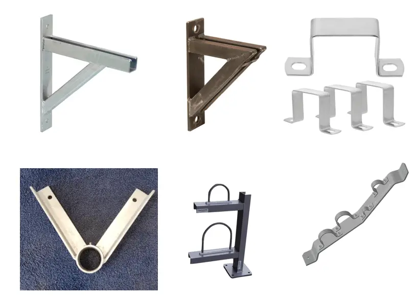
Wall Mount Pipe Brackets
Wall mount pipe brackets, as the name suggests, are brackets specifically designed to attach pipes to vertical surfaces such as walls. They are commonly used in applications where pipes need to be run along the walls, either to save space or to maintain a certain aesthetic appearance. Wall mount brackets come in various styles, including pipe clamp brackets, split rings, and clevis hangers, depending on the specific requirements of the piping system. These brackets securely hold the pipe in place, prevent sagging, and ensure the pipes remain safely affixed to the wall. They are also known as pipe wall brackets. Fig. 1 below shows various types of pipe support brackets.
Fig. 1: Various Types of Pipe Support Brackets
Conclusion
Pipe support brackets are integral components of any piping infrastructure, providing stability, safety, and longevity to the system. By understanding the various types of brackets available, following proper installation procedures, and recognizing their importance, engineers, contractors, and maintenance personnel can ensure the seamless functioning of pipe systems across residential, commercial, and industrial applications. Properly supported pipes lead to more reliable and efficient operations, safeguarding the infrastructure for years to come.
Online Course on Pipe Support Engineering
If you want to learn more details about pipe support engineering then the following online course is a must for you:
Trapeze hangers are support structures designed to suspend multiple pipes from overhead structures, such as ceilings or beams. They consist of horizontal supports (often a metal bar or channel) from which pipes are hung using brackets or clamps. When it comes to supporting pipes in various industrial and commercial settings, trapeze hangers have emerged as a popular and effective solution. These versatile supports offer numerous benefits over traditional methods, making them a go-to choice for engineers, architects, and construction professionals. In this article, we’ll learn about trapeze hangers and explore the advantages they bring to the table.
What is a Trapeze Hanger?
A trapeze hanger is a type of pipe support system used in various industrial, commercial, and construction applications. It is designed to suspend pipes or ducts from a ceiling, overhead structure, or framework, keeping them securely in place while allowing for adjustments if necessary. This is basically a strut-based pipe-hanging support solution.
The use of trapeze hangers dates back to the early days of plumbing and HVAC systems. As industrialization progressed, the need for effective pipe support systems became critical, leading to the development of specialized hanging methods.
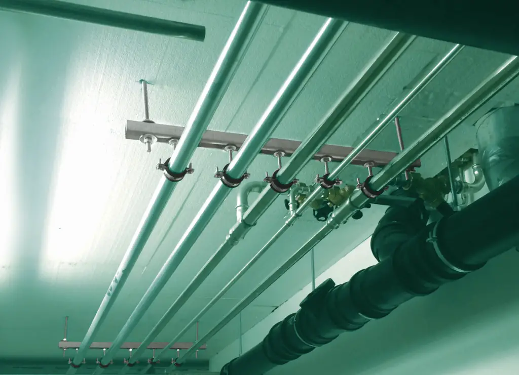
The name “trapeze hanger” comes from its distinctive shape, resembling the form of a trapeze used in gymnastics. The hanger consists of a horizontal bar (usually made of steel) that is supported by vertical rods or wires at each end. The suspended pipes are then attached to the horizontal bar, which evenly distributes the load along its length. Fig. 1 (Image Credit: https://www.walraven.com/) below shows a typical trapeze hanger assembly supporting pipes.
Fig. 1: Example of Trapeze Hanger Supports
Components of a Trapeze Hanger Pipe Support
A trapeze hanger assembly typically consists of several key components that work together to support and suspend pipes or ducts from a ceiling or overhead structure. These components can vary depending on the specific design and manufacturer, but the following are common elements found in most trapeze hanger systems:
Horizontal Bar (Trapeze Bar): The horizontal bar is the main component of the trapeze hanger and gives it its characteristic shape. It is usually made of steel and serves as the primary support for the suspended pipes or ducts. The horizontal bar is where the pipes or ducts are attached using various accessories.
Vertical Support Rods/Wires: These are the vertical components that connect the horizontal bar to the ceiling or overhead structure. They provide the necessary stability and load-bearing capacity to hold the entire trapeze hanger system in place. The number of vertical supports used may vary based on the length of the horizontal bar and the weight of the pipes being supported.
Threaded Rods or Bolts: Threaded rods or bolts are used to connect the horizontal bar to the vertical support rods or wires. They allow for adjustments in height and facilitate the proper alignment of the trapeze hanger system.
Clamps or Attachments: Clamps or attachments are used to secure the pipes or ducts to the horizontal bar. These may include U-bolts, channel clamps, beam clamps, or other specialized fasteners that provide a secure connection while accommodating different pipe sizes and configurations.
Locknuts and Washers: These components are used in conjunction with threaded rods to secure the attachments to the horizontal bar. Locknuts prevent loosening due to vibrations, while washers help distribute the load and protect the surface of the horizontal bar.
Hanging Hardware: In some cases, additional hanging hardware such as hooks or clips may be used to suspend the trapeze hanger system from the ceiling or overhead structure. These provide a reliable connection point for the vertical support rods or wires.
Corrosion Protection: Depending on the application and environment, trapeze hangers may be constructed from materials with corrosion-resistant properties. This helps to ensure the long-term durability and integrity of the hanger system, especially in harsh or corrosive environments.
Optional Accessories: Some trapeze hanger systems may include optional accessories like pipe insulation clamps, roller hangers, or sway braces to further enhance the functionality and support of the overall piping infrastructure.
Types of Trapeze Hangers
Trapeze hangers come in various types, each suited for different applications. Understanding the types can help in selecting the right hanger for a specific project.
Standard Trapeze Hangers
Standard trapeze hangers consist of two vertical supports and a horizontal beam. These are typically made from steel or aluminum and can support various pipe sizes.
Adjustable Trapeze Hangers
Adjustable trapeze hangers feature components that can be modified to accommodate different pipe diameters or configurations. This flexibility makes them suitable for dynamic environments where changes are common.
Pre-Insulated Trapeze Hangers
Pre-insulated trapeze hangers are designed for insulated pipes, often seen in HVAC systems. They provide thermal protection and reduce condensation issues by isolating the pipe from its surroundings.
Rigid and Flexible Trapeze Hangers
Rigid trapeze hangers are designed to hold pipes firmly in place, while flexible hangers allow for some movement, accommodating thermal expansion and contraction.
Materials Used in Trapeze Hangers
The materials used to fabricate trapeze hangers significantly influence their performance and longevity.
Steel
Steel is the most common material for trapeze hangers due to its strength and durability. Galvanized steel is often used for added corrosion resistance, making it suitable for outdoor or humid environments.
Aluminum
Aluminum trapeze hangers are lightweight and resistant to corrosion, making them ideal for applications where weight is a concern. However, they are generally less robust than their steel counterparts.
Stainless Steel
Stainless steel hangers provide excellent corrosion resistance and are often used in food processing or chemical applications, where hygiene and durability are paramount.
Composite Materials
Innovative composite materials are emerging in trapeze hanger production, offering a combination of lightweight properties and resistance to corrosion.
Fig. 2: Typical Trapeze Hangers for Industrial Applications
Advantages of Trapeze Hangers for Pipe Supporting
Trapeze hangers provide the following advantages while supporting a pipe:
Versatility and Flexibility:
One of the key advantages of trapeze hangers is their versatility. They can be used to support a wide range of pipe sizes and configurations, making them suitable for various applications. Whether you need to support a single pipe or multiple pipes at different elevations, trapeze hangers can be customized to meet your specific requirements. This flexibility saves time and effort during installation and ensures a perfect fit for the project at hand.
Optimal Load Distribution:
Trapeze hangers are designed to evenly distribute the load along the length of the support system. The unique trapeze shape and the use of sturdy materials like steel ensure that the weight of the pipes is evenly distributed, reducing the risk of stress concentrations and potential structural failures. This ensures the long-term integrity of the piping system and minimizes maintenance costs.
Easy Installation:
Compared to other pipe support systems, trapeze hangers offer ease of installation. They typically come pre-fabricated or with detailed installation instructions, making the setup process straightforward for construction crews. This not only saves time but also reduces the likelihood of errors during installation, leading to more efficient and cost-effective project execution.
Enhanced Adjustability:
As construction projects evolve, the need for adjustments in pipe layouts often arises. Trapeze hangers allow for easy and precise adjustments, facilitating modifications without compromising the overall stability of the support system. This feature is particularly useful in scenarios where there are changes in pipe routing or when adding additional pipes to the system.
Corrosion Resistance:
Trapeze hangers are commonly constructed using materials with excellent corrosion resistance properties, such as stainless steel or galvanized steel. This ensures that the supports remain durable and reliable even in harsh environmental conditions or corrosive atmospheres, enhancing the longevity of the entire piping infrastructure.
Cost-Effectiveness:
While trapeze hangers might seem like a premium solution, their cost-effectiveness becomes apparent when considering their long-term benefits. Their durable nature and low maintenance requirements result in reduced life-cycle costs compared to other pipe support systems, making them a financially sound investment for any construction project.
Compliance with Building Codes:
Engineers and architects must adhere to strict building codes and safety standards when designing and constructing pipe support systems. Trapeze hangers are designed and tested to meet these industry regulations, ensuring that the supported pipes are safe, secure, and compliant with the necessary guidelines.
Applications of Trapeze Hangers
Trapeze hangers are utilized in various industries, each with unique requirements.
Plumbing
In plumbing, trapeze hangers support water supply and drainage pipes, ensuring they remain secure and free from damage.
HVAC Systems
Trapeze hangers are commonly used in HVAC installations to support ductwork and piping, maintaining system efficiency and performance.
Industrial Applications
In manufacturing and industrial settings, trapeze hangers support heavy pipes and conduits, contributing to the overall safety of the facility.
Commercial Construction
In commercial buildings, trapeze hangers are crucial for organizing and supporting plumbing, HVAC, and electrical systems.
Residential Construction
In homes, trapeze hangers help support plumbing systems and provide structural integrity in basements and attics.
Considerations When Choosing Trapeze Hangers
The main parameters that must be looked upon while selecting a trapeze hanger for a specific service are:
Load Capacity: Ensure the trapeze hanger can support the weight of the pipes and any additional loads they may carry.
Environmental Conditions: Consider the environment where the hangers will be installed. Corrosion-resistant materials may be necessary in humid or chemically aggressive settings.
Code Compliance: Ensure that the selected trapeze hangers comply with local building codes and regulations.
Installation Requirements: Consider the complexity of installation. Some trapeze hangers may require specialized knowledge or tools.
Conclusion
In summary, trapeze hangers offer numerous advantages for pipe support in various industrial and commercial applications. Their versatility, optimal load distribution, ease of installation, enhanced adjustability, corrosion resistance, cost-effectiveness, and compliance with building codes make them a superior choice for any project.
As construction practices continue to evolve, trapeze hangers are likely to become an even more integral part of modern pipe support systems, providing engineers and construction professionals with a reliable, efficient, and long-lasting solution to support their piping infrastructure needs.
Trapeze hangers find application in HVAC (heating, ventilation, and air conditioning) systems, plumbing, fire protection, and various industrial piping installations. Their versatility and reliability make them a popular choice for engineers, architects, and construction professionals seeking effective pipe support solutions.
Online Course on Pipe Support Engineering
If you want to learn more details about pipe support engineering then the following online course is a must for you:
In industrial processes and manufacturing plants, precise control over various variables such as temperature, pressure, flow, and level is essential to ensure efficient and safe operations. One of the critical components that enable this level of control is the modulating control valve or modulating valve. Modulating control valves play a pivotal role in regulating the flow of fluids or gases in a system, offering flexibility and precision in adjusting process parameters. In this article, we will explore the fundamentals of modulating control valves, their applications, and the benefits they bring to industrial processes.
What are Modulating Control Valves?
A modulating control valve is a device designed to maintain a specific process variable at a desired setpoint by continuously adjusting the flow rate of the fluid or gas passing through it. Unlike on/off valves, which operate in a binary manner, modulating valves can regulate flow with infinite variability, allowing for precise control and smooth operation.
The core components of a modulating control valve include an actuator, a valve body, and a positioner. The actuator is responsible for moving the valve plug, which controls the flow rate, while the positioner receives signals from the process controller to position the actuator accordingly, maintaining the desired setpoint.
What is Modulation?
In the context of modulating valves, modulation refers to the ability of the valve to continuously vary the flow rate of a fluid or gas passing through it in response to changes in the process variable being controlled. The goal of modulation is to maintain a specific process variable, such as temperature, pressure, level, or flow rate, at a desired setpoint.
Modulation is achieved by adjusting the valve opening, which in turn regulates the flow of the fluid or gas. The extent of the valve opening is controlled by an actuator, which is typically powered by air, electricity, or hydraulic pressure. The actuator receives signals from a process controller that monitors the process variable and compares it to the desired setpoint. Based on this comparison, the actuator positions the valve’s closure element (such as a plug or disk) to allow more or less flow through the valve, aiming to bring the process variable closer to the desired setpoint.
The speed and precision with which the valve can modulate the flow are critical to maintaining stable and accurate control. Therefore, modulating valves are often equipped with positioners, which are devices that ensure the actuator accurately positions the valve closure element in response to the control signals from the process controller.
Types of Modulating Control Valves
Modulating control valves come in various types, each designed to suit specific applications and requirements. The selection of a particular type depends on factors such as the nature of the fluid or gas being controlled, the desired level of precision, the operating conditions, and the intended application. Here are some common types of modulating control valves:
Modulating Globe Valve:
Globe valves are perhaps the most widely used type of modulating control valve. They have a linear motion and provide excellent throttling control, making them suitable for applications requiring precise and fine adjustments in flow rates. Globe Modulating valves are commonly used in industries such as chemical, petrochemical, and power generation. They provide tight shut-offs.
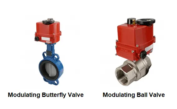
Modulating Ball Valve:
Ball valves are known for their quick opening and closing action, making them ideal for on/off applications. However, they can also be used for modulating control when equipped with a specialized actuator and positioner. Modulating ball valves (Fig. 1) are commonly used in industries like oil and gas, water treatment, and HVAC systems.
Fig. 1: Modulating Ball and Butterfly Valves
Modulating Butterfly Valve:
Butterfly valves have a simple and compact design, with a circular disk as the closure element. They offer good modulating control capabilities and are commonly used in large-scale applications where space and weight considerations are important, such as in water distribution and wastewater treatment. Modulating butterfly valves (Fig. 1) are durable, relatively easy to maintain, and can handle large flow rates. They are often found in systems where space is limited.
Modulating Diaphragm Valve:
Diaphragm valves are primarily used for controlling flow rates of corrosive or abrasive fluids. They have a flexible diaphragm as the closure element, which is particularly suitable for preventing contamination of the fluid by avoiding contact with the valve components. Diaphragm valves are commonly found in the pharmaceutical, chemical, and food industries and in systems where the fluid is corrosive or abrasive.
Applications of Modulating Control Valves
Modulating control valves find applications across a wide range of industries, including:
Process Industries: In chemical, petrochemical, and pharmaceutical industries, modulating control valves are used to regulate fluid flow and maintain accurate process parameters, ensuring product quality and safety.
Power Generation: In power plants, these valves control steam flow to turbines, enabling precise regulation of power generation based on electricity demand.
HVAC Systems: Modulating control valves in heating, ventilation, and air conditioning systems help maintain comfortable indoor temperatures by adjusting the flow of heating or cooling fluids.
Water Treatment: Modulating control valves are employed in water treatment plants to regulate the flow of chemicals, water, or wastewater, ensuring efficient treatment processes.
Oil and Gas Production: In the oil and gas industry, modulating control valves are used for regulating the flow of crude oil, natural gas, and other fluids in production, refining, and transportation processes.
Benefits of Modulating Control Valves
Enhanced Efficiency: Modulating control valves provide precise control, reducing fluctuations and overshooting, leading to improved energy efficiency and reduced operating costs.
Process Optimization: These valves allow operators to fine-tune process variables, optimize production, and meet strict quality standards.
Reduced Wear and Tear: Modulating valves can extend the lifespan of equipment by reducing sudden pressure changes and eliminating unnecessary stress on pipelines and machinery.
Safety and Reliability: Precise control of critical processes enhances safety by preventing unexpected deviations and potential hazards.
Automation Integration: Modulating control valves can be seamlessly integrated into automation systems, allowing for remote control and monitoring.
Best Practices for Modulating Valve Management
To ensure the effective and reliable operation of modulating control valves, consider the following best practices:
Regular Maintenance: Conduct routine inspections and maintenance to keep valves in optimal condition.
Calibration: Regularly calibrate control valves to maintain accuracy and responsiveness.
Positioner Tuning: Properly tune positioners to match the requirements of specific processes.
Training and Knowledge: Ensure operators are well-trained in control valve operation and troubleshooting.
Data Analysis: Utilize data from control systems to identify trends and optimize valve performance.
In conclusion, modulating control valves are essential tools for maintaining precise control over critical process variables in various industries. By integrating these valves into industrial processes and following best practices, businesses can enhance efficiency, productivity, and safety, ultimately contributing to their overall success.
Online Courses on Piping Design and Engineering
If you wish to dig deeper and learn more about elements of piping design and engineering then the below-mentioned online courses will help you to do so: