Plumbing and pipe fittings play a pivotal role in both commercial and residential facilities, underpinning effective functionality in various aspects of daily operations. Among the integral components of pipe fittings are elbows, which facilitate changes in the direction of the flow. While they are a common fixture, understanding their different types – specifically street elbows and piping elbows – can significantly enhance the efficiency and dependability of your plumbing system. This knowledge can also aid in making informed decisions when it comes to the installation, maintenance, and repairs of pipe systems. In this leg of our exploration, we’ll dissect the composition, function, and utility of street elbows and piping elbows, giving you a clear-cut insight into these integral elements of your plumbing framework.
Understanding a Street Elbow
What is a Street Elbow?
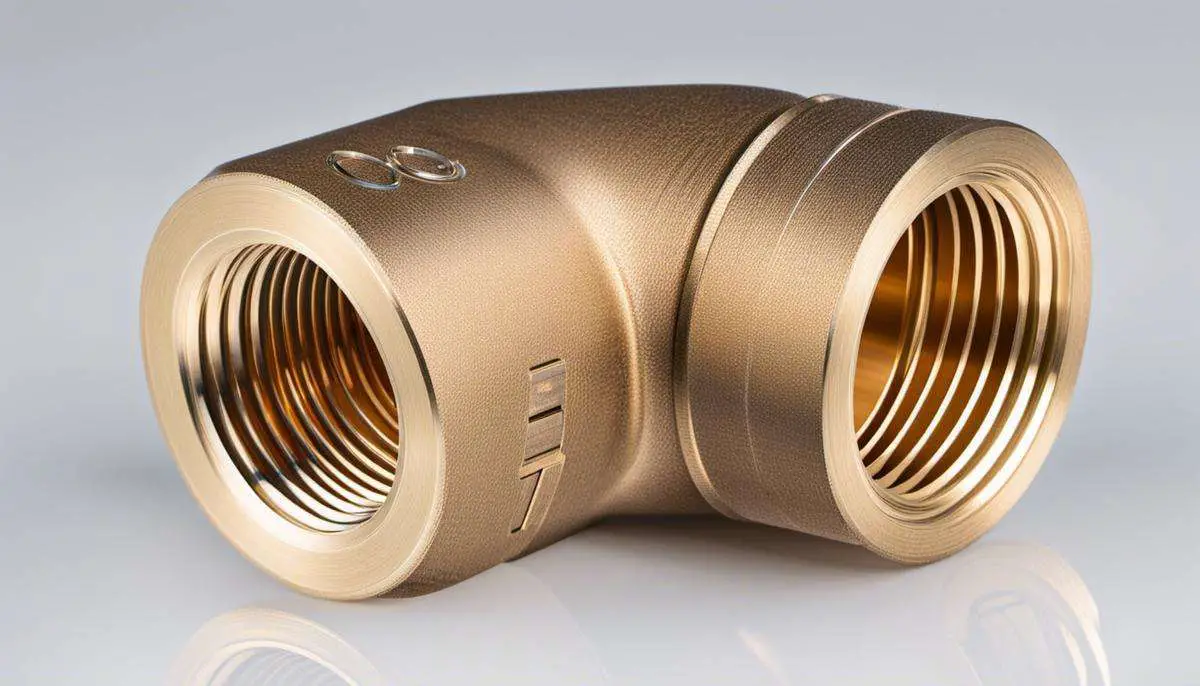
A street elbow is a type of plumbing fitting that is used to change the direction of flow in a piping system. Named for its shape, a street elbow is a 90-degree or 45-degree elbow with one male end and one female end. The male end, often referred to as the ‘street’ end, is made to fit into a different fitting or pipe, while the female end is designed to receive another pipe or fitting. The design of a street elbow allows it to connect two pipes at a corner, creating a change in the direction of liquid flow.
Uses of a Street Elbow
Street elbows are commonly used in both residential and commercial plumbing systems. In homes, they may be used in the installation of toilets, bathtubs, showers, or sinks. In commercial applications, street elbows can be found in water supply lines, heating systems, and various industrial piping systems. They are also essential components found in fire sprinkler systems and in residential and commercial irrigation systems.
Materials and Selection Criteria
Street elbows can be made from a variety of materials including brass, copper, steel, and PVC. The choice of material depends on factors such as the type of liquid or gas being transported, the operating temperature and pressure, and overall system requirements. Brass and copper street elbows, for instance, are often used in water supply lines for their superior resistance to corrosion and ability to withstand high temperatures. PVC street elbows are more commonly used for drainage and wastewater applications due to their durability and lower cost.
Differences Between a Street Elbow and a Piping Elbow
The primary difference between a street elbow and a piping elbow is the type of connections on their ends. A street elbow has one male end and one female end, which allows it to be directly connected to another fitting or pipe. This differs from a standard piping elbow, which typically has two female ends and is designed to connect two separate pipes together.
Another key difference between the two is their uses. As previously mentioned, street elbows are often used in applications where there is a need to alter the direction of flow around a corner. In contrast, piping elbows, also known as pipe elbows or elbow fittings, are often used in applications where there is a need for a more complex change in direction, such as in the construction of a serpentine or spiral pipe run.
Lastly, while both types of elbows come in 90-degree and 45-degree angles, pipe elbows are also available in other angles such as 22.5 degrees and 60 degrees. This allows for more flexibility in designing complex pipe runs.
Final Thoughts
At first glance, street elbows and piping elbows might appear to be identical, but they have distinct features such as connection types and applications, as well as their specific design nuances. Knowing these variations can facilitate the selection of the appropriate fitting based on the individual exigencies of different plumbing or piping circumstances.

Introduction to Piping Elbows
Diving Deeper into Piping Elbows
Piping elbows serve a crucial role in the layout of a piping system, specifically in redirecting the flow of fluids. Essentially, they enable turns of 90 or 45 degrees in the pathway of the pipe. Various sectors, encompassing plumbing, heating, air conditioning, and others that necessitate intricate networks of pipes, depend on these piping elbows.
The fundamental function of a piping elbow is to provide a flexible and effective conduit for the flow of fluid or gas in a pipeline. In the absence of this critical component, creating desired angles or directions in a pipeline would be a significant challenge, especially in restricted or specific spaces.
In connection with the fabrication material for these piping elbows, a range of substances can be utilized. The selection hinges on considerations such as durability, temperature resistance, capacity to withstand pressure, and resistance to chemical reactions. These materials could range from stainless steel, carbon steel, brass, copper, and even PVC.
Piping elbows come in various shapes and sizes correlating to their specific uses. Typically, the diameter of an elbow, which could be the same as or different from that of each connecting pipe, indicates its size.
Distinguishing the Street Elbow
A street elbow, often referred to as a street ell, is a type of piping elbow with a unique feature. It has a female thread on one end and a male thread on the other. This specific design is coined “street” because of its common use in installing water supply lines in public street landscapes.
The main advantage of a street elbow over a standard one is its ease of use in tighter spaces. Due to its male-to-female design, it eliminates the need for an additional connector between the fitting and the pipe, affording compact installations.
Like regular piping elbows, street elbows are also created from various materials like stainless steel, brass, and PVC. They are highly versatile, finding use in both residential and commercial applications, including natural gas, compressed air, and hydronic heating systems.
Distinctive Characteristics of Street and Piping Elbows
Both street elbows and piping elbows are integral to controlling the path of a piping system, but each has a unique design and application. Their main distinction is how they are physically constructed and consequently used.
A standard elbow comes with two female threads at each end, facilitating the interconnection of two pipe sections. Contrastingly, a street elbow features a female end and a male end, thus enabling it to couple directly with another fitting or pipe without the need for an extra joint. This design attribute makes street elbows a more efficient solution in constrained or narrow spaces, where the use of additional fittings can be difficult.
When it comes to deciding between these two types of elbows, the choice is largely dictated by the particular requisites of the pipe system arrangement. Your decision to use a standard elbow or a street elbow will hinge on factors such as the size of the pipe, location, accessibility, and sometimes the budgetary constraints of your plumbing project.
Differentiating Between Street Elbows and Piping Elbows
Delving into the Specifics of a Street Elbow
Often termed a ‘street ell,’ a street elbow is a specific kind of pipe fitting created to modify the course of a piping system. One of its defining traits is its design which includes one male end and one female end. The male end of a street elbow is typically inserted directly into another fitting or a receiving piece of equipment. This direct connection aptly earns it the name ‘street.’ These fittings are employed extensively in both commercial and residential plumbing systems and are also common in air, gas, and steam pipe networks.
The fundamental role of a street elbow is to alter the route of a pipe system, generally by 45 or 90 degrees, but other angles are also feasible. They are frequently utilized where pipes need to skirt around obstacles or navigate within narrow spaces. This is where regular elbows often fall short, as they may not offer enough clearance. Street elbows, therefore, present an efficient solution to change pipe routes without the need for additional fittings or extra space.
Contrasting with a Piping Elbow
On the other hand, a piping elbow, or simply an elbow, is a standard type of pipe fitting also used to change the direction of the piping system. The main difference lies in the ends of the fitting. Unlike the street elbow, a standard elbow has two female ends, which require a separate fitting to connect to each end. This means it must be connected to another piece of pipe or fitting to make a change in direction.
Notably, piping elbows come in a variety of angles, not just 90 and 45 degrees, offering flexibility in designing complex piping systems. They are often used in larger piping systems where more complex changes in direction are required.
Usage Scenarios to Illustrate Differences
To better appreciate the differences between a street elbow and a piping elbow, consider a couple of usage scenarios. In a plumbing system where the pipes need to bend around a corner in a confined space, a street elbow is probably the ideal choice. Its male end can fit directly into a corner fitting, enabling a smooth, compact bend without requiring extra space for additional fittings.
In contrast, if you’re constructing a more complex piping system requiring multiple bends and connections, a standard piping elbow may be more suitable. Its two female ends can accept pipes or other fittings on both sides, providing greater flexibility and facilitating the design and installation of more intricate piping systems.
Deciding Between a Street Elbow and a Piping Elbow
In the world of plumbing, the choice between a street elbow and a piping elbow can depend on various factors such as the specific needs of your piping system, the available space, and the necessary additional fittings. For instances that involve tight quarters, the combined interface of a street elbow can make a significant difference. On the other hand, for more complex systems, the versatility offered by a piping elbow might be the better choice. Either way, this decision ultimately rests on the unique requirements of your piping system and the configuration you aim to create.
Choosing the Right Elbow for Your Plumbing
Understanding a Street Elbow
The concept of a street elbow, also known as a street ell or pipe fitting, relates to a specialized type of plumbing or piping fitting designed to connect a pipe and another fitting at a specific angle. The term “street” traces back to when one end of the elbow was designed to be inserted into a piece of pipe or fitting, hence dubbed male (street), and the other end was configured to have a pipe or fitting inserted into it, thus being called female.
What sets street elbows apart is their characteristic pipe thread that directly links to another pipe or fitting without the need for extra connectors. This feature proves particularly beneficial in limited spaces where combining two fittings and a short pipe might be impracticable, successfully saving both time and minimizing the risk of leaks.
Understanding Piping Elbows
On the contrary, a piping elbow, often just called an elbow, is a different type of plumbing fitting. Unlike the street elbow, both ends are either male or female. These rely on additional connectors, typically in the form of short, straight pieces of pipe known as nipples, to join them to other pipes or fittings.
These two different types of elbows are used in different circumstances. Where you would use one versus the other depends on several factors: the specific plumbing design, the space available for pipe runs, the need to change the direction of the piping, and the desired reduction in the number of potential leak points.
Choosing Between a Street Elbow and a Piping Elbow
The primary advantage of a street elbow is its ability to connect directly to another pipe or fitting without the need for an additional connector. This feature is particularly valuable in tight spaces or when you want to minimize the number of connections, and thus potential leak points, in your piping system.
A regular elbow, however, provides greater versatility in that it can be used with nipples to customize the length, thus accommodating a greater range of distances between pipes or fittings.
When choosing between a street elbow and a regular elbow for your piping needs, it’s essential to consider not only the physical layout but also the type of fluid being carried in the pipe, the pressure and temperature ratings of the elbow, and the compatibility of the elbow’s material with the pipe and the fluid.
In general, where there is limited space or a need to reduce connections, a street elbow is often the best choice. If versatility or the ability to customize lengths is more critical, a regular elbow may be more suitable. In both cases, ensuring the elbow material is compatible with the pipe material and the fluid being transported is a crucial factor in selecting the right elbow for your needs.
Recognizing the inherent variability and unique characteristics of street elbows and piping elbows can lay a significant part in ensuring a durable and stable plumbing system. The type of elbow you choose can have both immediate and long-lasting effects on your pipe’s performance. Ultimately, it all boils down to understanding your specific plumbing needs, the material being transported in your pipes, and the structure of your pipe configuration. The choice between a street elbow and a piping elbow may seem small, but, when correctly made, it’s a choice that leads to enhanced system longevity and efficiency, while reducing the risk of leaks and faults. Expand your plumbing know-how, make informed decisions, and ensure your system lasts for the long haul.