Recent Posts

What is a Petroleum Tank? Its Types, Materials, Standards, and Specification

In the intricate network of industries that power our modern world, few substances hold as much importance as petroleum. As a source of fuel, raw materials, and energy, petroleum plays a vital role in sustaining our daily lives. But have you ever wondered about the unsung heroes that store this invaluable resource? Enter the petroleum tank – a crucial element in the petroleum supply chain that often goes unnoticed, yet is pivotal in ensuring the seamless distribution of liquid gold.

The Backbone of Energy Storage

Petroleum tanks serve as the backbone of energy storage, providing a safe and efficient means to house vast quantities of crude oil, refined products, and other derivatives. As the main product is oil, petroleum tanks are also popular as oil tanks. These tanks come in various shapes, sizes, and configurations, each designed to meet specific storage requirements. From massive cylindrical tanks dotting the landscapes of oil refineries to the more inconspicuous tanks nestled underground, each serves a distinct purpose.

Parts of a Petroleum Tank

Understanding the components of a petroleum tank is essential to grasp its functionality. Most tanks consist of the following key elements:

  • Shell: The outer cylindrical structure that contains petroleum. It is constructed using sturdy materials to withstand the immense pressure exerted by the stored liquid.
  • Roof: Designed to prevent external elements such as rainwater and debris from contaminating the stored petroleum. Floating roofs are commonly used to adjust the volume of the tank’s contents.
  • Bottom: The base of the tank that supports the weight of the stored petroleum. It is designed to prevent leakage and seepage into the ground.
  • Fittings and Valves: An intricate network of pipes, valves, and fittings facilitate the inflow, outflow, and monitoring of stored petroleum.
  • Secondary Containment: In many modern tanks, a secondary containment system acts as a safeguard, preventing any potential spills or leaks from reaching the environment.

Types of Petroleum Tanks

Petroleum tanks come in various types, each designed to fulfill specific storage and operational requirements. The choice of tank type depends on factors such as the type of petroleum product being stored, the location of the tank, safety considerations, and environmental regulations. Fig. 1 below shows typical examples of storage tanks.

Petroleum Storage Tanks
Fig. 1: Petroleum Storage Tanks

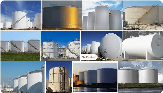
Here are some of the common types of petroleum tanks:

Above-Ground Storage Tanks (ASTs):

These tanks are situated on or above the ground surface and are commonly used in refineries, distribution terminals, and industrial facilities. They are easily accessible for inspection, maintenance, and cleaning. ASTs can have either fixed or floating roofs, and they are cost-effective to install and maintain.

Underground Storage Tanks (USTs):

Buried beneath the ground surface, USTs are often used at gas stations, residential areas, and places where space is limited. They offer advantages such as space conservation and reduced aesthetic impact. USTs are particularly useful for storing smaller quantities of petroleum products, like gasoline and diesel.

Floating Roof Oil Tanks:

These tanks have a floating roof that rests on the surface of the stored liquid. The roof moves up and down with the changing volume of the liquid due to temperature fluctuations. Floating roof tanks are commonly used for storing volatile petroleum products, like crude oil and gasoline, as the floating roof helps reduce vapor emissions and minimize the risk of fires and explosions.

Fixed Roof Oil Tanks:

These tanks have a permanent, non-floating roof. They are often used to store more stable products, such as heavy crude oils and asphalt. Fixed roof tanks can have cone roofs, dome roofs, or umbrella roofs. While they may not offer the same level of vapor emission control as floating roof tanks, they can still be equipped with vapor recovery systems to mitigate emissions.

Cone Roof Tanks:

These tanks have a cone-shaped roof that is sloped downward toward the center. They are commonly used for storing materials that do not require a floating roof but still need protection from environmental elements.

Dome Roof Tanks:

Dome roof tanks have a rounded, geodesic-shaped roof. These tanks are known for their structural strength and are often used for storing large volumes of petroleum products.

Spherical Tanks:

Spherical tanks are unique in design, resembling large spheres. They are used for storing liquids under high pressure, making them suitable for liquefied petroleum gas (LPG) and other pressurized products.

Horizontal Storage Tanks:

These tanks are oriented horizontally and are often used for above-ground storage of liquids. They can be used for various petroleum products, including crude oil and refined products.

Bunded Oil Tanks:

A bunded oil tank is a type of storage tank designed to provide an extra layer of protection against leaks, spills, and environmental contamination. It consists of two layers or walls – an inner tank that holds the oil and an outer ‘bund’ (a protective barrier) that surrounds the inner tank. In the event of a leak or spill from the inner tank, the outer bund is designed to contain the oil, preventing it from reaching the environment. Unlike secondary containment bunded spill pallets, which catch drips and leaks from oil drums and other containers, Bunded oil tanks are an all-in-one storage and bund solution. Bunded oil tanks are widely used for storing various types of oils, including heating oil, diesel, and other petroleum products. They are a safety measure to prevent oil-related incidents and minimize the risk of environmental damage.

Single Skin Oil Tanks:

Single-skin oil tanks are basic, single-layer storage tanks designed to hold oil. Unlike bunded tanks, they lack an outer protective layer (bund) to contain potential leaks or spills. While single-skin tanks are simpler and less expensive to install, they offer less environmental protection. Any leaks or spills from a single skin tank have a higher chance of directly impacting the surrounding area, potentially leading to soil and groundwater contamination. Due to their limitations in terms of environmental safety, single-skin tanks are becoming less common, especially in areas with stringent regulations.

Double Skin Oil Tanks:

Double-skin oil tanks, also known as twin-wall tanks or double-walled tanks, are similar to bunded tanks but with an additional layer of insulation between the inner tank and the outer skin. The primary purpose of the insulation is to provide an added safeguard against temperature fluctuations, which can help maintain the quality of the stored oil. Like bunded tanks, double-skin tanks provide a higher level of protection against leaks and spills compared to single-skin tanks. They are often used for storing sensitive petroleum products and are a preferred choice in regions with strict environmental regulations.

Open Top Oil Tanks:

An open-top oil tank refers to a type of storage tank that lacks a fully enclosed roof, resulting in an exposed opening at the top. These tanks are typically used for storing non-hazardous materials, as the lack of a sealed roof makes them unsuitable for containing volatile or hazardous substances. Open-top tanks are often used for applications such as storing water, wastewater, or certain industrial liquids. They are not commonly used for storing petroleum products due to the potential for vapor emissions, environmental contamination, and safety concerns associated with open access to the stored material.

Secondary Containment Tanks:

Some tanks, regardless of their primary design, incorporate secondary containment systems to provide an extra layer of environmental protection. These systems capture any potential leaks or spills, preventing them from reaching the surrounding environment.

Codes and Standards for Petroleum Tanks

Designing and constructing petroleum tanks involves adherence to various codes and standards to ensure safety, environmental protection, and compliance with industry best practices. Here are some important design codes and standards commonly used for petroleum tanks:

API 650: Welded Steel Tanks for Oil Storage:

Published by the American Petroleum Institute (API), this standard provides requirements for the design, fabrication, assembly, and inspection of welded steel tanks used for the storage of petroleum liquids, including crude oil and various refined products. It covers aspects such as materials, design loads, tank shell and bottom design, corrosion protection, and more.

API 620: Design and Construction of Large, Welded, Low-Pressure Storage Tanks:

Another API standard, API 620, focuses on the design and construction of larger, low-pressure welded storage tanks. It covers aspects like design pressure, temperature, materials, and welding procedures for tanks that operate at pressures up to 15 psi (103 kPa).

API 653: Tank Inspection, Repair, Alteration, and Reconstruction:

API 653 provides guidelines for the inspection, repair, alteration, and reconstruction of above-ground storage tanks used for petroleum products. It outlines requirements for maintaining the integrity and safety of existing tanks, including assessment methods, repair techniques, and guidelines for returning tanks to service after modifications.

UL 142: Standard for Steel Aboveground Tanks for Flammable and Combustible Liquids:

Published by Underwriters Laboratories (UL), this standard covers requirements for the construction and testing of above-ground steel tanks used for storing flammable and combustible liquids, including many petroleum products. It addresses aspects like materials, welding, leakage prevention, and more.

NFPA 30: Flammable and Combustible Liquids Code:

Developed by the National Fire Protection Association (NFPA), NFPA 30 provides guidelines for the storage, handling, and use of flammable and combustible liquids, including petroleum products. It covers a wide range of topics, including tank design, installation, ventilation, and fire protection.

EN 14015: Specification for the Design and Manufacture of Site-Built, Vertical, Cylindrical, Flat-Bottomed, Above Ground, Welded, Steel Tanks for the Storage of Liquids at Ambient Temperature and Above:

This European standard provides requirements for the design and construction of site-built, above-ground storage tanks for various liquids, including petroleum products. It covers aspects such as materials, design considerations, fabrication, and testing.

ASME Boiler and Pressure Vessel Code (Section VIII, Division 1):

This code, developed by the American Society of Mechanical Engineers (ASME), provides guidelines for the design and construction of pressure vessels, including some types of tanks used in the petroleum industry. While it is not specific to petroleum tanks, certain provisions may apply depending on the tank’s characteristics.

ISO 28300: Petroleum, Petrochemical, and Natural Gas Industries – Venting of Atmospheric and Low-Pressure Storage Tanks:

This international standard provides guidance on the venting requirements for atmospheric and low-pressure storage tanks used in the petroleum, petrochemical, and natural gas industries. Proper venting helps prevent overpressure and vacuum conditions in tanks.

Materials for Petroleum Storage Tanks

Petroleum storage tanks are constructed using a variety of materials, each chosen based on factors such as the type of petroleum product being stored, the tank’s size, location, intended use, and regulatory requirements. Here are some common materials used for building petroleum storage tanks:

  • Steel: Steel is one of the most widely used materials for constructing petroleum storage tanks. It is known for its strength, durability, and suitability for a wide range of petroleum products. Tanks made from carbon steel or stainless steel are common in the industry. Carbon steel tanks are often coated or lined with protective materials to prevent corrosion and extend their lifespan. Stainless steel tanks are preferred when storing corrosive or high-temperature petroleum products.
  • Fiberglass Reinforced Plastic (FRP): FRP tanks are corrosion-resistant and lightweight, making them suitable for storing a variety of petroleum products. They are particularly useful for storing chemicals and acids that may corrode traditional steel tanks. FRP tanks can be designed to withstand a wide range of temperatures and are often used for underground storage due to their resistance to soil corrosion.
  • Concrete: Concrete tanks are commonly used for above-ground storage of petroleum products, especially in industrial settings. They are durable, fire-resistant, and can be constructed to various sizes and shapes. Concrete tanks may be reinforced with steel to enhance their structural integrity.
  • Composite Tanks: Composite tanks combine the benefits of different materials. For instance, a tank might have a steel shell with a corrosion-resistant inner lining made of a material like FRP. These tanks provide the strength of steel while minimizing the risk of corrosion or contamination.
  • Polyethylene (Plastic): Polyethylene tanks are lightweight, corrosion-resistant, and suitable for storing non-hazardous petroleum products such as water, lubricants, and some types of fuels. They are often used for smaller storage needs, especially in residential or non-industrial settings.
  • Coatings and Linings: Regardless of the tank’s main construction material, various coatings and linings can be applied to protect against corrosion, chemical reactions, and other environmental factors. Epoxy, polyurethane, and other specialized coatings are often used to extend the life of the tank and ensure the stored petroleum remains uncontaminated.

Petroleum Oil Tank Specification

Specifying a petroleum tank involves providing detailed information and requirements to ensure that the tank is designed, constructed, and installed to meet your specific needs and comply with industry standards and regulations. Here’s a step-by-step guide on how to specify a petroleum tank:

  1. Define Your Requirements: Start by clearly defining your requirements. Determine the type of petroleum product you will be storing (crude oil, gasoline, diesel, etc.), the desired tank capacity, the intended location (above ground, underground), and any specific environmental or safety considerations.
  2. Consult Regulations and Standards: Research and familiarize yourself with relevant industry standards and local regulations governing petroleum storage tanks. This could include standards from organizations like the American Petroleum Institute (API), the National Fire Protection Association (NFPA), and environmental agencies in your region.
  3. Select Tank Type and Material: Choose the appropriate tank type (e.g., above-ground, underground, bunded, double skin) based on factors such as safety, environmental protection, and product characteristics. Select a suitable tank material (steel, fiberglass, concrete, etc.) based on compatibility with the stored petroleum and potential corrosion concerns.
  4. Determine Design Parameters: Specify design parameters such as tank dimensions, capacity, shape, and any additional features like fittings, valves, vents, and access points. Consider factors like wind loads, seismic activity, and temperature variations that may affect the tank’s design.
  5. Include Safety Features: Ensure the tank is designed with safety features such as pressure relief devices, overfill protection, leak detection systems, and fire suppression equipment. Specify any secondary containment requirements for environmental protection.
  6. Coatings and Linings: If needed, specify the type of coatings or linings required to protect the tank from corrosion or chemical reactions with the stored petroleum. Consider factors like the corrosiveness of the product and potential interactions.
  7. Installation and Location: Define installation requirements, including the tank’s location, foundation specifications, anchoring methods, and any additional infrastructure needed for proper operation (e.g., piping, pumps).
  8. Inspection and Maintenance: Specify access points and provisions for regular inspection, maintenance, and cleaning. Ensure the tank design allows for easy monitoring of the tank’s condition and product levels.
  9. Documentation and Records: Request detailed documentation from the tank manufacturer or supplier, including engineering drawings, material certifications, quality control procedures, and warranties. Ensure that all relevant records are provided for compliance and future reference.
  10. Review and Approval Process: Establish a review and approval process to ensure that the tank design meets your specifications and regulatory requirements. Involve relevant stakeholders, such as engineers, safety experts, and regulatory authorities, as needed.
  11. Budget and Timeline: Clearly define your budget and project timeline expectations to ensure that the tank specification aligns with your financial and scheduling constraints.
  12. Communication: Maintain clear and open communication with the tank manufacturer or supplier throughout the process to address any questions, concerns, or modifications that may arise.

Ensuring Safety and Environmental Protection

Safety is paramount in the petroleum industry, and petroleum tanks are no exception. Rigorous engineering, strict maintenance protocols, and advanced monitoring systems work in tandem to prevent accidents, leaks, and environmental contamination. Regular inspections, leak detection mechanisms, and emergency response plans contribute to minimizing risks associated with petroleum storage.

Conclusion

Petroleum tanks may not always be in the limelight, but they are the unsung guardians of the precious liquid that powers our world. These tanks stand as silent sentinels, ensuring the availability of petroleum products while upholding safety standards and environmental protection. Understanding the significance of petroleum tanks shines a light on the intricacies of an industry that impacts every facet of our lives, from transportation to manufacturing to energy generation.

What is Petroleum Coke or Petcoke? Its Types, Applications, and Differences with Coal

In the world of energy and industrial processes, there exists a versatile and widely used material that often goes unnoticed despite its significant role in powering economies and industries. Petroleum coke, often simply referred to as “petcoke,” is a carbon-rich byproduct of the oil refining process that has found its way into various sectors, playing a crucial role in energy generation, manufacturing, and more. This article dives deep into the layers of petroleum coke, exploring its production, characteristics, applications, and environmental considerations.

What is a Petroleum Coke?

Petroleum coke, commonly referred to as petcoke, emerges as a byproduct during the refining of crude oil. This carbon-rich solid substance serves a range of industrial and commercial purposes, including its utilization as a fuel source in power plants and cement kilns. The visual characteristics of petcoke can range from deep black to dark grey or even a warm golden brown hue, contingent upon its composition and the specific refining methods applied. The sulfur content of petoleum coke displays considerable variation, encompassing grades featuring both exceptionally low and remarkably high sulfur concentrations.

The genesis of petcoke traces back to the conclusive thermal cracking process undertaken within Coker units. These units play a pivotal role in disassembling the lengthy hydrocarbon chains present in petroleum residues, ultimately converting them into shorter, more manageable chains. Petroleum coke is also known as Refinery Coke.

The Birth of Petroleum Coke: From Crude Oil to Carbon

Petroleum coke is a byproduct that emerges during the oil refining process, specifically from the residue left behind after the distillation of crude oil. This residue, known as “resid” or “bottom-of-the-barrel,” is the source material from which petroleum coke is derived. The refining process removes lighter hydrocarbons from the crude oil, leaving behind heavier fractions which are then subjected to further processing. Fig. 1 below shows some typical examples of Petroleum Coke.

Example of Petroleum Cokes
Fig. 1: Example of Petroleum Cokes

Distillation and Coking: The Transformation Process

The conversion of residual oil into petroleum coke involves a thermal decomposition process called coking. There are two primary methods of coking:

  • Delayed Coking: This process involves heating the residual oil in large, cylindrical drums at elevated temperatures. As the oil breaks down, the carbon content in the residue solidifies into petroleum coke while releasing volatile gases and liquids.
  • Fluid Coking: Fluid coking utilizes a fluidized bed reactor to heat the residual oil, resulting in the creation of petroleum coke and a mixture of gases and liquids.

Characteristics of Petroleum Coke

Petroleum coke comes in various forms, each with unique characteristics that make it suitable for specific applications. The most common types include:

  • Needle Coke: Recognized for its exceptional electrical conductivity and mechanical properties, needle coke is a vital component in the production of graphite electrodes for electric arc furnaces and lithium-ion batteries.
  • Fuel-Grade Petcoke: Used as a fuel source in power generation and cement kilns, fuel-grade petcoke is characterized by its high carbon content and low levels of sulfur and metals.
  • Green Coke: Green coke constitutes the unprocessed feedstock employed in the production of calcined coke. This solid carbon residual stems from the oil refining procedure and is characterized by its elevated levels of moisture and volatile constituents.
  • Calcined Petcoke: Calcination involves heating petroleum coke to high temperatures to remove volatile components, resulting in a product with enhanced properties such as higher carbon purity and improved density. Calcined petcoke is widely used in the production of anodes for the aluminum industry and as a raw material in the manufacturing of carbon products.

Specification of Petroleum Coke

Specifications for petroleum coke outline the characteristics and properties that define its quality and suitability for various industrial applications. These specifications serve as essential guidelines to ensure that the petcoke meets the desired standards and can be effectively used in processes such as energy generation, manufacturing, and more. Here are some of the key specifications that are typically considered for petroleum coke:

  1. Moisture Content: The moisture content of petcoke is a crucial parameter, as excessive moisture can affect its combustion efficiency and performance. Low moisture content is generally preferred for most applications.
  2. Volatile Matter: The volatile matter in petcoke contributes to its combustion behavior and can impact emissions. Certain applications require specific levels of volatile matter to ensure optimal performance and environmental compliance.
  3. Sulfur Content: Sulfur content is a critical specification due to its environmental implications. High sulfur content can lead to increased emissions of sulfur dioxide, which contributes to air pollution. Thus, lower sulfur content is often preferred, especially for applications with strict emission regulations.
  4. Ash Content: The ash content of petcoke is a measure of the inorganic material present. Higher ash content can lead to increased slagging and fouling in combustion processes, potentially affecting equipment performance.
  5. Fixed Carbon: Fixed carbon content is an important indicator of the energy content and combustion efficiency of petcoke. Higher fixed carbon content generally corresponds to higher calorific value and better combustion characteristics.
  6. Calorific Value: The calorific value or heating value of petcoke indicates the amount of energy it can release upon combustion. This is crucial for applications such as energy generation and industrial heating.
  7. Particle Size Distribution: The particle size distribution of petcoke can influence its handling, storage, and combustion properties. Different applications may require specific particle size ranges.
  8. Hardgrove Grindability Index (HGI): HGI is a measure of the grindability or ease of pulverizing petcoke. It is important for applications that involve grinding or pulverizing the material.
  9. Vanadium and Nickel Content: These trace elements can have an impact on the performance of catalysts and equipment in certain applications. Lower levels are generally preferred, particularly in applications like fluid catalytic cracking (FCC) units.
  10. Metal Content: Metal impurities, such as iron, can influence the reactivity and behavior of petcoke. Specific applications may have limits on metal content to prevent adverse effects.

The following table provides a typical specification of Petroleum Coke

SpecificationRangeMethod
Moisture Content2% maxASTM D3302
Volatile Matter8 – 14%ASTM D3175
Sulfur Content1 – 5%ASTM D4294
Ash Content0.2 – 1.5%ASTM D3174
Fixed Carbon85% minCalculated
Calorific Value14,000 – 15,500 Btu/lbASTM D5865
Particle Size (Sieve)0.2 – 3.0 mmASTM D5003
HGI (Hardgrove Index)40 – 60ASTM D409
Vanadium Content100 ppm maxASTM D5056
Nickel Content50 ppm maxASTM D5056
Metal Content (Fe)300 ppm maxASTM D5609
Table 1: Petroleum Coke Specification

Applications Across Industries

Petroleum coke finds its way into an array of industries, playing a crucial role in powering economies and driving technological advancements. Some of the prominent applications include:

Petroleum coke, with its diverse characteristics and properties, finds application across several industries and sectors. Its versatility, ranging from energy generation to manufacturing, makes it a valuable resource in various processes. Here are some prominent applications of petroleum coke:

1. Energy Generation:

  • Fuel for Power Plants: High-energy content and relatively low cost make petroleum coke a preferred fuel in power plants, aiding in electricity generation.
  • Co-firing with Coal: Petcoke can be co-fired with coal in power plants to enhance combustion efficiency and reduce greenhouse gas emissions.

2. Industrial Processes:

  • Cement Manufacturing: Petcoke serves as an alternative fuel and raw material in cement kilns, providing high heat input and reducing fossil fuel consumption.
  • Steel Production: As a reducing agent, petcoke aids in the smelting process in blast furnaces and electric arc furnaces, contributing to steel production.

3. Aluminum Industry:

  • Anode Production: Calcined petcoke is used as a key component in the production of anodes for aluminum smelting, ensuring efficient electrolytic processes.

4. Carbon and Graphite Industries:

  • Graphite Electrodes: High-quality needle coke derived from petcoke is essential in manufacturing graphite electrodes for electric arc furnaces and lithium-ion batteries.
  • Carbon Products: Calcined petcoke finds application in the production of carbon products such as brake linings, carbon brushes, and more.

5. Refractories:

  • Raw Material: Petroleum coke is used as a raw material in the manufacturing of refractory bricks and other refractory materials due to its high-temperature resistance.

6. Foundry Industry:

  • Reducing Agent: Petcoke can be employed as a reducing agent in foundries during the melting of metals and alloys.

7. Glass Industry:

  • Fuel Source: Petcoke’s high calorific value makes it suitable for use as a fuel in glass manufacturing furnaces.

8. Chemical Industry:

  • Feedstock: In certain chemical processes, petcoke can serve as a feedstock for the production of various chemicals.

9. Petcoke Gasification:

  • Advanced Technology: In some regions, petcoke is used as a feedstock for gasification processes, converting it into syngas for further chemical or energy applications.

10. Waste-to-Energy Applications:

  • Co-firing in Waste-to-Energy Plants: In waste-to-energy facilities, petcoke can be co-fired with other waste materials to generate heat and electricity.

Differences between Petroleum Coke and Coal: Pet Coke vs Coal

Petroleum coke (petcoke) and coal are both carbon-rich solid fuels, but they have distinct origins, compositions, and characteristics. Here are some key differences between petroleum coke and coal:

1. Origin:

  • Petroleum Coke: Petcoke is a byproduct of the oil refining process. It is formed from the residual material left over after the distillation of crude oil. Petcoke is produced in refineries and is a carbon-rich material.
  • Coal: Coal is a fossil fuel that is primarily formed from the remains of plants that lived and died millions of years ago. It is found in underground coal seams and is extracted through mining.

2. Composition:

  • Petroleum Coke: Petcoke is composed mainly of carbon, with varying amounts of hydrogen, sulfur, nitrogen, and other elements. It also contains trace amounts of metals like vanadium and nickel.
  • Coal: Coal is composed of carbon, hydrogen, oxygen, nitrogen, sulfur, and other elements. The specific composition of coal can vary widely depending on its type and source.

3. Sulfur Content:

  • Petroleum Coke: The sulfur content of petcoke can vary widely, with some grades having low sulfur content and others having high sulfur content.
  • Coal: Coal can also have varying sulfur content, with some types of coal containing higher sulfur levels, leading to potential environmental issues when burned.

4. Energy Content:

  • Petroleum Coke: Petcoke generally has a higher energy content (calorific value) compared to coal on a per-unit-mass basis.
  • Coal: The energy content of coal can vary depending on its type and grade.

5. Applications:

  • Petroleum Coke: Petcoke is often used as a fuel source in power plants, cement kilns, and industrial processes. It is also utilized in the production of carbon and graphite products, including graphite electrodes for various industries.
  • Coal: Coal has a wide range of applications, including energy generation (electricity and heat), industrial processes, steel production, and more.

6. Environmental Impact:

  • Petroleum Coke: Burning petcoke can release greenhouse gases, sulfur dioxide, and other pollutants into the atmosphere. Its use is associated with air quality and environmental concerns, particularly when high-sulfur petcoke is burned.
  • Coal: Coal combustion releases carbon dioxide, sulfur dioxide, nitrogen oxides, and particulate matter into the air. The environmental impact of coal is well-documented and has led to efforts to reduce its use and improve emissions control technologies.

7. Production Process:

  • Petroleum Coke: Petcoke is a byproduct of the oil refining process, specifically from the coking of residual oil.
  • Coal: Coal is mined from underground or surface mines and undergoes various processing steps before it is used as a fuel.

The major differences between coal and petroleum coke are reproduced below in Table 2.

AspectCoalPetroleum Coke
OriginFossil fuel formed from ancient plant remainsA byproduct of the oil refining process
CompositionCarbon, hydrogen, oxygen, nitrogen, sulfurMainly carbon, with varying elements (hydrogen, sulfur, nitrogen, metals)
Energy ContentVaries with coal type and gradeGenerally higher energy content compared to coal
ApplicationsEnergy generation, industrial processes, steel production, heating, etc.Fuel in power plants, cement kilns, carbon, and graphite product manufacturing
Environmental ImpactReleases CO2, SO2, NOx, particulatesReleases CO2, SO2, NOx, particulates, potential environmental concerns
Production ProcessMined from underground or surface mines, various processing stepsA byproduct of the oil refining, produced during the coking process
Table 2: Coal vs Petroleum Coke

Environmental Considerations and Future Outlook

While petroleum coke serves various essential functions, its production and use raise environmental concerns. Emissions from burning petcoke, especially the high sulfur content in some grades, contribute to air pollution and can have adverse effects on air quality and human health. As industries move towards cleaner and more sustainable practices, the use of petroleum coke is being scrutinized, and research is being conducted to develop greener alternatives and more efficient utilization methods.

Conclusion

Petroleum coke, a hidden gem within the world of industrial byproducts, plays a vital role in diverse sectors, from energy production to manufacturing. Its varied forms cater to different applications, enabling industries to function efficiently and effectively. As we navigate the path toward a more sustainable future, it is imperative to strike a balance between harnessing the benefits of petroleum coke and addressing the environmental challenges it poses. As research and innovation progress, we can anticipate the evolution of petroleum coke’s role in our ever-changing industrial landscape.

What is a Distillation Column? Its Types, Working, and Components

In the vast landscape of chemical engineering, few processes stand as iconic and fundamental as distillation. At the heart of this critical process lies the distillation column – a towering, cylindrical apparatus that plays a pivotal role in separating and purifying mixtures, ranging from crude oil to alcoholic spirits. This article aims to demystify the distillation column, exploring its inner workings, applications, and significance in various industries.

What is the Distillation Process?

Distillation is a separation technique that capitalizes on the differences in boiling points of components within a mixture. When a mixture is heated, the component with the lower boiling point vaporizes first, rises through the column, and condenses back into liquid form as it cools down. This vaporization-condensation cycle repeats, causing a gradual separation of the mixture into its individual components. Distillation columns enhance this process by providing ample surface area for efficient vapor-liquid contact and separation.

What is a Distillation Column?

A distillation column resembles a tall vertical cylinder, often hundreds of feet high, equipped with an array of trays or packing materials. These components aid in creating multiple vapor-liquid contact stages, maximizing the separation efficiency. Fig. 1 shows a typical distillation column.

A distillation column is a tall, cylindrical static equipment used in chemical engineering and industrial processes to separate and purify mixtures of liquid components based on their differing boiling points. The column facilitates the process of fractional distillation, where the mixture is heated to cause vaporization of the component with the lowest boiling point. As the vapor rises through the column, it comes into contact with liquid on trays or packing materials, leading to equilibrium and separation of components. The condensed vapors, referred to as distillate, are collected and further processed, while the remaining liquid, known as the bottoms, may contain the higher boiling point components. Distillation columns are essential in various industries, including petroleum refining, chemical manufacturing, pharmaceuticals, and beverage production, playing a crucial role in achieving product purity and quality.

A Typical Distillation Column
Fig. 1: A Typical Distillation Column (Image Credit: https://niroonamad.com/)

Components of a Distillation Column

A distillation column is a complex apparatus composed of several key components that work in harmony to facilitate the separation and purification of mixtures. These components ensure efficient vapor-liquid contact and separation. The main components of a distillation column include:

Reboiler:

Located at the bottom of the column, the reboiler is responsible for heating the liquid mixture to initiate vaporization. As heat is applied, the component with the lowest boiling point vaporizes and rises through the column.

Distillation Trays or Packing Materials:

These are situated within the column at specific intervals. They provide a surface area for vapor-liquid interaction, promoting equilibrium between the vapor and liquid phases. Trays consist of perforated plates placed horizontally across the column while packing materials (such as rings, saddles, or structured packing) increase surface area for better separation efficiency.

Column Shell:

The cylindrical body of the distillation column provides structural support and houses the trays or packing materials. It is designed to withstand the internal pressure and temperature conditions.

Vapor Outlets:

These are located at the top of the column and allow the separated vapor components to exit the column and proceed to the condenser.

Condenser:

Positioned at the top of the column, the condenser cools down the vaporized components, causing them to condense back into liquid form. This condensed liquid is then collected and referred to as the distillate.

Distillate Receiver:

This is a vessel or container that collects the condensed distillate from the condenser. It is designed to separate the condensed liquid from any remaining vapor.

Reflux System:

The reflux system is responsible for returning a portion of the condensed liquid (distillate) back to the column. This reflux helps maintain proper temperature and vapor-liquid equilibrium, improving separation efficiency.

Reflux Drum:

The reflux drum is a vessel that collects and temporarily stores the returning reflux liquid before it is reintroduced into the column. It helps regulate the flow of reflux and prevents sudden disturbances in the column operation.

Bottoms Outlet:

Located at the bottom of the column, the bottom outlet allows the heavier components of the mixture to be withdrawn as a liquid stream. This stream may contain the least volatile components.

Column Internals:

These include various accessories and devices used to optimize column performance, such as distributors for even liquid distribution on trays, collectors for vapor distribution, and demisters to prevent the entrainment of liquid droplets in the vapor stream.

Pressure Relief System:

Distillation columns are operated under specific pressure conditions. A pressure relief system, such as safety valves or rupture discs, is incorporated to ensure the column’s integrity in case of pressure buildup.

Working Principle: Fractional Distillation

The fundamental principle behind distillation is fractional distillation, which leverages the concept of equilibrium. As the vapor rises through the column, it encounters the liquid on the trays or packing. The vapor-liquid equilibrium leads to the separation of components, with the component of a lower boiling point vaporizing more readily and rising to a higher tray. The trays or packing materials facilitate this equilibrium at multiple stages, enhancing the separation efficiency. Fig. 2 below shows the typical products that are obtained from a crude distillation column at different temperatures.

Crude Distillation Column
Fig. 2: Typical Products from a Crude Distillation Column (Image Credit: https://www.wermac.org/)

Types of Distillation Columns

Distillation columns come in various types, each designed to address specific separation challenges and optimize efficiency based on the characteristics of the mixture being processed. Here are some common types of distillation columns:

Batch Distillation Column:

In batch distillation, a fixed amount of mixture is loaded into the column, processed, and then the products are collected. It’s suitable for small-scale operations, research, and when dealing with mixtures that are difficult to separate. Batch distillation is commonly used in the production of high-quality spirits and certain pharmaceuticals.

Continuous Distillation Column:

Continuous distillation columns manage an uninterrupted flow of feed. Only in the event of an issue with the column or adjacent process equipment do interruptions occur. These columns excel at accommodating substantial throughput and represent the more prevalent than batch distillation columns. Continuous Distillation columns can be further divided into the following:

  • Fractionating Column: This is the most common type of distillation column and is widely used in various industries. It includes trays or packing materials to create multiple vapor-liquid equilibrium stages, enabling the separation of a wide range of components based on their boiling points. Fractionating columns are extensively used in petroleum refining, chemical manufacturing, and beverage production.
  • Packed Distillation Column: These columns are filled with packing materials (such as rings, saddles, or structured packing) that provide a large surface area for vapor-liquid interaction. Packed columns are often used for applications where heat and mass transfer are critical, making them suitable for separating heat-sensitive or difficult-to-distill mixtures.
  • Azeotropic Distillation Column: This type of column is designed to handle azeotropic mixtures, where two or more components have similar boiling points and form a constant-boiling mixture. Special techniques, such as the addition of an entrainer or using extractive distillation, are employed to break the azeotrope and achieve effective separation.

Reactive Distillation Column:

In reactive distillation, chemical reactions occur simultaneously with the separation process. This integration of reaction and separation allows for higher product yields, reduced equipment footprint, and improved energy efficiency. Reactive distillation is commonly used in the production of chemicals, such as esters and biodiesel.

Vacuum Distillation Column:

Vacuum distillation operates at reduced pressure to lower the boiling points of components, making it suitable for separating heat-sensitive materials or reducing thermal degradation. Vacuum distillation is commonly used in the refining of crude oil and in the production of high-quality products, such as essential oils.

Steam Distillation Column:

This method involves the introduction of steam into the distillation process. Steam distillation is particularly useful for separating volatile compounds from heat-sensitive materials, such as extracting essential oils from plants.

Extractive Distillation Column:

In extractive distillation, an entrainer or solvent is added to the mixture to alter the relative volatility of the components, making separation easier. This technique is often used for separating azeotropic mixtures or for challenging separations that cannot be achieved through conventional distillation.

Molecular Distillation Column:

Molecular distillation is a high-vacuum distillation process used to separate compounds with very high boiling points or those that are thermally sensitive. It is commonly employed in the production of pharmaceuticals, edible oils, and other high-value products.

Applications of Distillation Column

Distillation columns find applications across various industries, each with its unique requirements:

  • Petroleum Refining: In crude oil refining, distillation columns separate crude oil into fractions based on different boiling points, yielding valuable products like gasoline, diesel, and jet fuel.
  • Chemical Production: Distillation is vital in the production of chemicals, pharmaceuticals, and specialty chemicals, enabling the separation and purification of complex mixtures.
  • Beverage Industry: Distillation columns are integral to producing alcoholic beverages like whiskey, vodka, and gin. They separate alcohol from fermented mixtures to create high-proof spirits.
  • Environmental Applications: Distillation columns play a role in environmental processes such as water purification and wastewater treatment, removing impurities through separation.

Challenges and Innovations

While distillation columns are highly effective, they also face challenges such as energy consumption and the separation of azeotropic mixtures (where components have similar boiling points). Ongoing research focuses on enhancing energy efficiency, utilizing advanced column designs, and incorporating hybrid separation technologies to overcome these challenges.

Conclusion

The distillation column stands as an engineering marvel that underpins countless industrial processes. Its ability to separate and purify mixtures has revolutionized industries ranging from energy to beverages. As technology advances and sustainability becomes increasingly important, the distillation column will continue to evolve, ensuring the efficient and environmentally responsible separation of mixtures for generations to come.

What is Burst Testing? Burst Test vs Hydrostatic Test

In the world of materials testing, there’s a method that goes beyond the surface to uncover the true strength and resilience of various substances. Burst testing, also known as burst strength testing or burst pressure testing, is a crucial evaluation technique used across industries to determine how much internal pressure a material can withstand before it ruptures or bursts. This test sheds light on the structural integrity and reliability of materials, ensuring they can withstand the rigors of real-world applications.

What is Burst Testing?

At its core, burst testing involves subjecting a material, usually in the form of a sealed sample or container, to increasing internal pressure until it ruptures. The pressure is typically applied using a hydraulic or pneumatic system, and the process is closely monitored to record the pressure at which the rupture occurs. This critical point is then used to assess the burst strength of the material.

Burst tests are conducted under controlled conditions to ensure accurate and repeatable results. The data obtained from these tests is essential for quality control, product development, and regulatory compliance across a wide range of industries, including manufacturing, packaging, automotive, aerospace, and more.

In the piping industry, the burst test is quite popular for expansion bellows and pressure vessels to determine the ultimate pressure resistance. The hydraulic pressure on the bellows is slowly increased till it fails. And based on the burst test results, a safety factor is applied which finally establishes the ultimate pressure rating of the expansion bellow.

Importance of Burst Testing

Burst testing offers several key benefits that make it an indispensable tool in the world of materials testing:

  • Safety Assurance: In industries where materials are used in high-pressure environments, such as pressurized containers or hydraulic systems, knowing the burst strength of materials is crucial to prevent catastrophic failures that could lead to accidents, injuries, or damage.
  • Quality Control: Burst testing is a valuable quality control measure during the manufacturing process. It helps identify weak points or inconsistencies in the material’s composition or fabrication, ensuring that only products meeting the desired specifications are released to the market.
  • Product Development: Engineers and designers rely on burst testing to fine-tune and optimize their designs. By understanding a material’s burst strength, they can make informed decisions about material selection, thickness, and other factors that influence the overall performance and longevity of the final product.
  • Regulatory Compliance: Many industries are subject to strict regulations and standards regarding the use of materials in specific applications. Burst testing provides the necessary data to demonstrate compliance with these regulations and ensure the safety and reliability of products.

Types of Burst Testing

Several methods of burst testing are commonly used, each catering to different types of materials and applications:

  • Diaphragm Burst Testing: This method involves clamping a material sample between two diaphragms and subjecting it to increasing pressure until the diaphragm ruptures. It’s often used for flexible materials like plastics, rubber, and textiles.
  • Constant-Rate-of-Traverse (CRT) Burst Testing: CRT testing applies a constant force to a sample, resulting in a gradually increasing pressure. This method is suitable for rigid materials such as metal or glass.
  • Mullen Burst Testing: Commonly used in the paper and packaging industry, Mullen burst testing measures the pressure required to rupture a sheet of paperboard. It helps assess the strength and durability of packaging materials.
  • Ball Burst Testing: In this method, a metal ball is pressed against a material until it bursts. It’s often used for evaluating the burst strength of nonwoven materials and textiles.

Burst Test Machine

A burst test machine, also known as a burst tester, is a specialized testing equipment used to conduct burst tests on various materials and products. Burst testing is a critical process that involves subjecting a material to increasing internal pressure until it ruptures. This test helps determine the maximum pressure a material can withstand before it fails or bursts, providing valuable insights into its structural integrity and quality. Burst test machines are essential tools in industries such as manufacturing, packaging, textiles, automotive, aerospace, and more.

Key Components of a Burst Test Machine:

  • Pressure Generation System: This system is responsible for applying internal pressure to the test specimen. It typically consists of hydraulic or pneumatic components, such as pumps, cylinders, regulators, and valves, that work together to gradually increase the pressure until the material ruptures.
  • Clamping Mechanism: The test specimen needs to be securely held in place during the test. The clamping mechanism ensures that the specimen remains properly positioned and prevents any external factors from affecting the test results.
  • Pressure Measurement and Control: Burst test machines are equipped with pressure sensors or gauges to accurately measure and control internal pressure. This data is crucial for determining the burst strength of the material and analyzing its behavior under pressure.
  • Safety Features: Given the potentially high pressures involved in burst testing, safety features are paramount. Machines may include emergency shut-off mechanisms, pressure relief valves, and protective enclosures to ensure the safety of operators and prevent accidents.
  • Data Acquisition and Analysis: Modern burst test machines often come with data acquisition systems that record and analyze the pressure data during the test. This information is useful for generating test reports, conducting statistical analysis, and comparing test results.
  • Software Interface: Many advanced burst test machines are equipped with user-friendly software interfaces that allow operators to set test parameters, monitor the test progress, and visualize the pressure curves in real-time.

Burst Test Standards

Burst test standards are established guidelines and specifications that define the procedures, equipment, and parameters for conducting burst tests on various materials and products. These standards ensure consistency, accuracy, and reliability in testing, and they are widely used across industries to assess the burst strength and performance of materials. ASME Sec VIII Div 1 is the main code that governs the burst test for components required in the oil and gas, chemical, and petrochemical industries

Here are some of the other prominent burst test standards used in different sectors:

  • ASTM D3786 – Standard Test Method for Bursting Strength of Textile Fabrics – Diaphragm Bursting Strength Tester Method: This ASTM standard outlines the procedure for determining the bursting strength of textile fabrics using a diaphragm bursting strength tester. It is commonly used in the textile and apparel industry to evaluate the strength of fabrics.
  • ASTM D6797 – Standard Test Method for Bursting Strength of Fabrics Constant-Rate-of-Traverse (CRT) Ball Burst Test: This standard provides guidelines for conducting burst tests on fabrics using the Constant-Rate-of-Traverse (CRT) ball burst test method. It is another important standard for evaluating the burst strength of textiles.
  • ISO 13938-2 – Textiles – Bursting properties of fabrics – Part 2: Pneumatic method for determination of bursting strength and bursting distension: This ISO standard specifies a pneumatic method for determining the bursting strength and bursting distension of fabrics. It is widely recognized in the textile industry.
  • ASTM F1140 – Standard Test Methods for Internal Pressurization Failure Resistance of Unrestrained Packages: This standard is used for conducting burst tests on various packaging materials and packages. It evaluates the ability of packages to withstand internal pressure without failure.
  • ASTM F2054 – Standard Test Method for Burst Testing of Flexible Package Seals Using Internal Air Pressurization Within Restraining Plates: Specifically focusing on package seals, this ASTM standard outlines the procedure for conducting burst tests on flexible package seals.
  • ISO 11607-1 – Packaging for terminally sterilized medical devices – Part 1: Requirements for materials, sterile barrier systems, and packaging systems: This ISO standard is essential in the medical device industry and includes guidelines for burst testing of packaging materials for terminally sterilized medical devices.
  • API RP 1110 – Pressure Testing of Liquid Petroleum Pipelines: In the oil and gas industry, this American Petroleum Institute (API) recommended practice provides guidance on the hydrostatic burst testing of liquid petroleum pipelines.
  • ASME Section VIII, Division 1 – Boiler and Pressure Vessel Code: This code, developed by the American Society of Mechanical Engineers (ASME), provides guidelines for the design, fabrication, inspection, and testing of pressure vessels. It includes requirements for burst testing.
  • EN 12115 – Rubber and thermoplastics hoses and hose assemblies for liquid or gaseous chemicals: In the field of industrial hoses, this European standard includes requirements for burst testing of hoses and hose assemblies used for conveying chemicals.

Burst Test for Packaging

Burst testing for packaging is a critical quality control and performance evaluation method used to assess the strength and integrity of various types of packaging materials, including bags, pouches, films, bottles, containers, and more. This testing helps determine how well packaging can withstand internal pressure before rupturing, ensuring that it can safely contain and protect its contents under real-world conditions. Burst testing is particularly important in industries such as food and beverage, pharmaceuticals, consumer goods, and industrial products.

Differences between the Burst test and the Hydrostatic test

Here is a tabulated comparison between Burst Testing and Hydrostatic Testing:

AspectBurst TestHydrostatic Test
PurposeMeasures the maximum pressure a material can withstand before rupture.Checks for leaks, defects, and strength under static fluid pressure.
MethodInternal pressure is gradually increased until rupture occurs.Material or component is submerged in a fluid and pressurized uniformly.
ApplicationCommon in industries like manufacturing, packaging, textiles, etc.Widely used in pipelines, plumbing, tanks, and pressure vessels.
MeasurementDetermines burst strength and failure pressure of a material.Identifies leaks, deformations, and material behavior under pressure.
Safety FocusFocuses on understanding material limits and preventing catastrophic failure.Emphasizes checking for weaknesses or vulnerabilities that could cause leaks.
Pressure SourcePressure is applied using hydraulic or pneumatic systems.Fluid pressure is applied using water or other suitable test fluid.
ResultsProvides information about the material’s burst strength and structural integrity.Identifies weaknesses, defects, and potential failure points.
Quality ControlUsed for product development, quality control, and safety assurance.Ensures compliance with standards, regulations, and safety requirements.
EquipmentRequires specialized burst testing equipment and fixtures.Involves hydrostatic test equipment like pumps, pressure gauges, and test chambers.
Material TypesApplicable to various materials, including plastics, metals, textiles, and more.Suitable for a wide range of materials, such as metals, plastics, and ceramics.
Common IndustriesManufacturing, packaging, automotive, textiles, etc.Oil and gas, construction, aerospace, and manufacturing industries.
Table 1: Burst Test bs Hydrostatic Test

While both burst testing and hydrostatic testing serve distinct purposes, they are essential techniques for ensuring the safety, quality, and reliability of materials and products across different industries. Burst testing focuses on understanding material strength and failure points, while hydrostatic testing assesses a component’s ability to withstand fluid pressure and checks for potential leaks or weaknesses.

Conclusion

Burst testing plays a pivotal role in ensuring the safety, quality, and reliability of materials used in various industries. By subjecting materials to controlled pressure until they burst, engineers and manufacturers gain insights into their performance limits and can make informed decisions about their use. From enhancing product development to complying with regulations, burst testing empowers industries to create safer and more efficient products that stand up to real-world challenges.

Types of Pipe Threads: NPT, BSP, Metric, and Unified Threads

In the world of piping, plumbing, construction, and manufacturing, pipe threads are an essential element that holds everything together, quite literally. These unassuming yet crucial components play a pivotal role in ensuring leak-free connections, structural integrity, and efficient fluid transport. In this comprehensive guide, we’ll dive deep into the world of pipe threads, exploring their types, applications, standards, and best practices.

What is a Pipe Thread?

Pipe threads are helical ridges carved onto the outer surface of a pipe or fitting, designed to create a secure connection between two components. These threads serve two primary purposes:

  • to facilitate the assembly and disassembly of pipes or fittings and
  • to create a seal that prevents leaks.

A variety of screw thread variations have developed to cater to fastening and hydraulic systems. The careful selection of the appropriate screw thread plays a vital role in establishing a seal that is impervious to leaks.

Types of Pipe Threads

Pipe threads come in various designs, each tailored to specific needs. Broadly, there are four major types of pipe threads:

1. American National Pipe Thread:

The American National Pipe (Also Known as National Pipe Thread) Thread is a widely used thread standard in the United States for screw threads used on threaded pipes and pipe fittings. This encompasses both tapered and straight thread series designed to fulfill diverse requirements, such as enhancing stability, ensuring pressure-tight seals, or accomplishing both objectives simultaneously. These classifications are denoted by complete names alongside abbreviations like NPT, NPS, NPTF, or NPSC. The National Pipe Thread series have the 60° included angle.

Types of American National Pipe Threads:

The various types of American National Pipe Threads or National Pipe Threads are as follows:

Abbreviated Pipe Thread FormExpanded Pipe Thread formFull nameRemarks/Comment
NPTNational pipe taperAmerican National Standard Taper Pipe ThreadTapered for sealing, often without any thread sealant; for connections in nearly every type of service
NPSNational pipe straightAmerican National Standard Straight Pipe ThreadFor rigidity; sealable only with sealant; sometimes male straight is mated with female tapered for low-pressure sealing. NPS threads are used when a seal is not required but a mechanical connection is desired.
NPSCNational pipe straight–couplingAmerican National Standard Straight Pipe Thread for CouplingsFor general couplings
NPSFNational pipe straight–fuel and oilDryseal USA (American) Standard Fuel Internal Straight Pipe ThreadInternal only, straight
NPSHNational pipe straight–hoseAmerican National Standard Straight Pipe Thread for Hose CouplingsFor hose couplings
NPSINational pipe straight–intermediateDryseal USA (American) Standard Intermediate Internal Straight Pipe ThreadSimilar to NPSF but slightly larger; internal only, straight
NPSLNational pipe straight–locknutAmerican National Standard Straight Pipe Thread for Loose-fitting Mechanical Joints with LocknutsFor use with locknuts
NPSMNational pipe straight–mechanicalAmerican National Standard Straight Pipe Thread for Free-fitting Mechanical JointsFor various rigid mechanical uses
NPTFNational pipe taper–fuel and oilDryseal USA (American) Standard Taper Pipe ThreadFor dry seal connections in nearly every type of service, especially fuel connections
NPTRNational pipe taper–railingAmerican National Standard Taper Pipe Thread for Railing JointsFor railings
PTF-SAE SHORTPipe taper, fuel, SAE, shortDryseal SAE Short Taper Pipe ThreadNamed after SAE International; similar to NPTF but one turn shorter
Table 1: Types of National Pipe Threads
Fig. 1: NPT Thread vs BSP Thread

2. BSP (British Standard Pipe Thread):

Common in the UK and many parts of the world, BSP pipe threads are also adopted internationally for interconnecting and sealing pipes and fittings providing reliable sealing capabilities. There are two types of distinguished BSP pipe threads:

  • BSPT: British Standard Pipe Taper thread (BSPT), whose diameter increases or decreases along the length of the thread; and
  • BSPP (British Standard Pipe Parallel): Unlike tapered threads, BSPP threads are parallel, ensuring a consistent diameter along the thread length. They are often used in low-pressure applications.

The Thread form in BSP pipe thread types follows the British Standard Whitworth standard with the symmetrical V-thread in which the angle between the flanks is 55° (measured in an axial plane)

3. ISO Metric Thread:

The ISO Metric Thread is a standardized system for screw threads, established by the International Organization for Standardization (ISO). This thread standard is widely used globally, especially in countries that have adopted the metric system of measurement. ISO Metric Threads are designed to facilitate precise and interchangeable connections between threaded components, ensuring compatibility across various applications and industries.

Key characteristics of ISO Metric Threads include:

  • Metric Measurement: ISO Metric Threads are defined using metric units, such as millimeters for thread diameter and pitch. This allows for consistent and standardized measurements, making it easier to select the right threads for specific applications.
  • Thread Classes: ISO Metric Threads come in different classes that define the level of tolerance and fit between mating threads. The most common thread classes are “fine” and “coarse,” with variations like “extra fine” also available for specific applications.
  • Thread Direction: ISO Metric Threads typically have a right-hand thread direction, meaning they are tightened by turning clockwise. Left-hand threads are less common but can be found in specialized applications.
  • Applications: ISO Metric Threads find extensive use in industries like manufacturing, automotive, machinery, and construction. They are employed for various purposes, including fastening, joining, and assembling components.
  • Variants: ISO Metric Threads encompass a range of thread types, such as ISO metric coarse thread (M), ISO metric fine thread (MF), and ISO metric extra fine thread (MFEF). Each variant is suited for different applications based on factors like load-bearing capacity and fastening requirements.

The adoption of ISO Metric Threads has facilitated international standardization and eased the process of sourcing, manufacturing, and maintaining threaded components. By adhering to ISO Metric Thread specifications, industries can benefit from improved compatibility, reduced errors, and increased efficiency in their operations.

4. Unified Screw Threads:

Unified Screw Thread, often referred to simply as Unified Thread, is a standard system of screw threads that was developed in the United States. It is used for a wide range of applications across industries, providing a consistent and interchangeable thread design for various fastening and assembly purposes. The Unified Thread system was established to streamline the previously fragmented thread standards in the U.S. and promote compatibility between different components.

Key features of Unified Screw Threads include:

  1. Inch Measurement: Unified Thread uses inch-based measurements for thread diameter, pitch, and other thread parameters. This makes it particularly relevant in countries where the imperial system is used.
  2. Thread Classes: Unified Thread comes in different classes that define the level of tolerance and fit between mating threads. Common classes include “Unified Coarse” (UNC) and “Unified Fine” (UNF).
  3. Thread Direction: Unified Threads typically have a right-hand thread direction, meaning they are tightened by turning clockwise. Left-hand threads are less common but are used in specialized applications.
  4. Applications: Unified Threads are widely used in various industries, including manufacturing, automotive, aerospace, construction, and more. They are suitable for fastening, joining, and assembling components, ensuring reliable connections.
  5. Variants: Unified Thread offers several variations, such as Unified Extra Fine (UNEF) threads for applications requiring higher thread density or finer adjustments.

The Unified Screw Thread system has significantly simplified the process of selecting and using threaded components, promoting interchangeability and reducing confusion that could arise from different thread standards. By adhering to the Unified Thread specifications, industries can benefit from improved compatibility, reduced manufacturing costs, and increased efficiency in assembling products and structures.

Parts of a Pipe Thread: Pipe Thread Nomenclature

Pipe threads consist of several key components that work together to create a secure and leak-free connection between pipes and fittings. Understanding these components is essential for proper assembly and maintenance. Here are the main parts of a pipe thread:

  • Thread Crest: The thread crest is the topmost point of the helical ridge on a male thread. It’s the highest point of the thread profile.
  • Thread Root: The thread root is the bottommost point of the helical groove on a female thread. It’s the lowest point of the thread profile.
  • Thread Flank: The thread flank is the sloping surface between the thread crest and the thread root. Threads have two flanks, an upper flank, and a lower flank, which meet at the thread crest.
  • Thread Pitch: The thread pitch is the distance between two consecutive thread crests or roots. It determines how tightly the threads fit together and affects the ease of assembly and disassembly.
  • Thread Angle: The thread angle is the angle between the flanks of the thread. Different thread standards have different thread angles; for example, the thread angle for NPT threads is 60 degrees.
  • Taper: Tapered threads, like NPT and BSPT, have a gradual change in diameter over the length of the thread. This taper helps create a tight seal as the threads are tightened.
  • Thread Length: The thread length refers to the portion of the pipe or fitting that is threaded. It determines how much engagement there is between the male and female threads when connected.
  • Thread Direction: Threads can be right-handed or left-handed. In most applications, right-handed threads are used, meaning they are tightened by turning clockwise. Left-handed threads are less common and are tightened by turning counterclockwise.
  • Thread Relief: The thread relief is a flat surface at the end of a threaded section that provides clearance for the engagement of threads and prevents them from bottoming out prematurely.
  • Thread Engagement: Thread engagement refers to the depth to which male and female threads interact when connected. Sufficient thread engagement is important for achieving a strong and secure connection.
  • Thread Seal: Threaded connections often require a sealant to ensure a leak-free joint. Thread sealants, such as Teflon tape or pipe dope, are applied to the male threads to enhance sealing properties.
  • Thread Identification: Threads are often identified using specific markings, such as size, pitch, and type. These markings help ensure the proper matching of threads during assembly.

Applications and Industries

Pipe threads find applications across a wide range of industries, including:

  • Plumbing: Connecting pipes and fittings in residential, commercial, and industrial plumbing systems.
  • Oil and Gas: Facilitating the transportation of fluids in pipelines and well systems.
  • Manufacturing: Assembling machinery and equipment that involve fluid flow.
  • Chemical Processing: Ensuring leak-free connections for the transfer of hazardous chemicals.
  • Fire Protection: Creating connections for sprinkler systems in buildings.

Standards and Regulations

To ensure compatibility and safety, various organizations have established standards for pipe threads:

  • ASME B1.20.1: This standard covers pipe threads, including NPT, NPS, and NPSM threads, used in the United States.
  • ISO 7-1: Pertinent to BSPT and BSPP threads, this ISO standard is prevalent in Europe and other metric-centric regions.
  • ISO 724: General Purpose Metri Screw Threads
  • ASME B1.1: Unified Inch Screw Threads

Best Practices for Working with Pipe Threads

  • Proper Thread Engagement: Ensure sufficient thread engagement for a secure connection. Incomplete engagement can result in weak joints and leaks.
  • Use of Thread Sealants: Depending on the application and thread type, thread sealants like Teflon tape or pipe dope can enhance sealing properties.
  • Avoid Over-Tightening: Excessive force can damage threads, leading to leaks or stripped threads. Follow manufacturer recommendations for torque values.
  • Regular Inspection: Periodic checks for wear, corrosion, or damage are essential to maintaining the integrity of pipe threads.

Differences Between NPT and BSP Threads

Here’s a comparison table outlining the key differences between NPT (National Pipe Thread) and BSP (British Standard Pipe) threads:

AspectNPT (National Pipe Thread)BSP (British Standard Pipe)
Thread TypeTaperedParallel
Thread Angle60 degrees55 degrees (BSPP), 60 degrees (BSPT)
Sealing MechanismTapered design aids in sealingSealing is achieved through an O-ring or gasket
Common ApplicationsGeneral piping and plumbing (US)Piping and Plumbing (UK and some other countries)
UsageWidely used in the United StatesPrevalent in the UK and Europe
Thread Names and AbbreviationsNPT (National Pipe Thread), NPTF (National Pipe Thread Fuel), NPS (National Pipe Straight), NPSM (National Pipe Straight Mechanical)BSPP (British Standard Pipe Parallel), BSPT (British Standard Pipe Tapered)
Compatibility with Each OtherNot interchangeable with BSPP or BSPT threadsNot interchangeable with NPT threads
Table: NPT vs BSP Pipe Threads

The differences between the NPT and BST thread pitch dimensions are provided below:

Pipe Thread SizesPitch (Threads per Inch)
NPT/NPSBSP
1/82728
1/41819
3/81819
1/21414
¾1414
111 ½11
1 ¼11 ½11
1 ½11 ½11
211 ½11
2 ½811
3811
3 ½811
4811
5811
6811
Table: Pipe Thread Pitch as per NPT and BSP Pipe Threads

Conclusion

Pipe threads are the unsung heroes of various industries, enabling the seamless flow of fluids and the construction of reliable structures. Understanding the different thread types, applications, and best practices is crucial for achieving leak-free connections and ensuring the longevity of your projects. Whether you’re a plumber, engineer, or simply someone curious about the intricate world of pipe systems, a solid grasp of pipe threads will undoubtedly serve you well.

Pipe Ferrules: Uses, Types, Materials, Installation, and Benefits

Pipe fittings play a crucial role in the plumbing and piping industry, enabling the connection and flow of fluids within various systems. Among these fittings, pipe ferrules are essential components that ensure leak-proof and secure connections. In this comprehensive guide, we will delve into the world of pipe ferrules, exploring their uses, types, materials, installation methods, and the benefits they offer.

What is a Pipe Ferrule?

A pipe ferrule, also known as a compression ferrule fitting or compression ferrule sleeve, is a small cylindrical ring or collar made from various materials, including brass, stainless steel, copper, and plastic. It is used to create a tight, leak-proof connection between pipes, tubes, or hoses. The ferrule, along with other components like nuts and inserts, work together to create a secure and reliable joint.

Pipe ferrules come in a range of sizes. Larger pipe ferrules are crafted with specialized hardening processes, enhancing their leak resistance and ability to securely hold tubes even under elevated pressure conditions. Fig. 1 below shows some typical ferrule fittings:

Pipe Ferrules
Fig. 1: Pipe Ferrules

Components of a Pipe Ferrule

Ferrule fittings typically consist of several components that work together to create a robust connection. These components include:

  • Front Ferrule: This part of the ferrule creates a seal by compressing against the fitting body.
  • Back Ferrule: The back ferrule grips the tubing, enhancing the connection’s strength and stability.
  • Fitting Body: The body holds the ferrules in place and facilitates the connection.
  • Nut: The nut is used to tighten the ferrules and secure the connection.

Pipe Ferrule Materials

Ferrule fittings are available in a range of materials to accommodate different applications and environments. Common materials include:

  • Stainless Steel: Known for its corrosion resistance, making it suitable for harsh environments.
  • Brass: Offers good corrosion resistance and is often used in less demanding applications.
  • Copper: Used in industries such as HVAC and refrigeration due to its excellent thermal conductivity.
  • Plastic: Provides chemical resistance and is lightweight, making it suitable for certain fluid handling applications.
  • Aluminum alloy
  • Cast steel
  • Ceramic
  • Glass

Ferrule material is selected on a variety of factors such as material durability, connector mating frequency, surface finish over time, cost, and the material’s ability to retain end-face geometry.

Ferrule Fitting Sizes

Ferrule fittings come in various sizes and dimensions to fit different tubing and pipe sizes. The sizes are typically specified using standard measurements, such as inches or millimeters, and are designed to match industry standards. Common sizes range from 1/8 inch to larger sizes suitable for industrial applications.

Types of Pipe Ferrules

There are two types of ferrules; Single ferrule and double ferrule.

Single Ferrule:

Within single ferrule fittings, the ferrule’s tip serves a dual role. Firstly, it grips the tube by embedding itself, while also acting as a sealing element for the coupling body. It’s worth noting that single-ferrule fittings possess a lower pressure rating when compared to their twin-ferrule counterparts. Manufacturers meticulously design these ferrule fittings to align with operators’ preferences and to ensure user-friendly installation.

Twin or Double ferrule:

Double Ferrule
Fig. 2: Double Ferrule

Twin or double ferrule fittings consist of front and back ferrules. In these fittings, the back ferrule provides gripping action, while the front ferrule ensures a reliable seal. The double ferrule also referred to as a two-ferrule system, is accessible in various materials. Its dimensions match those of single ferrule fittings. The robust mechanical grip design of double ferrule fittings ensures a flawless connection. These fittings are versatile, suitable for tubing of different diameters and hardness levels.

Again Based on the connection process, the following types of pipe ferrules are found:

  • Compression Ferrules: These ferrules are commonly used for connecting copper, plastic, or stainless steel pipes. They consist of a compression nut, body, and ferrule. When the nut is tightened, it compresses the ferrule against the pipe, creating a tight seal.
  • Swage Ferrules: Swage ferrules are used to create a permanent connection between pipes or cables. They are often used in industries such as aerospace and marine, where reliability is of utmost importance. Swaging involves deforming the ferrule to grip the pipe tightly.
  • High-Pressure Ferrules: These ferrules are designed to withstand high-pressure applications, making them suitable for hydraulic systems, oil and gas pipelines, and industrial machinery.
  • Push-to-Connect Ferrules: These innovative ferrules allow for quick and easy installation without the need for special tools. They are commonly used in plumbing and pneumatic systems.

Installation Process

Installing pipe ferrules requires precision and care to ensure a proper connection. Here’s a step-by-step guide to installing compression ferrules, one of the most common types:

  • Cutting and Preparing the Pipe: Measure and mark the pipe to the desired length. Use a pipe cutter to create a clean, square cut.
  • Insert the Ferrule: Slide the Ferrule onto the pipe, ensuring it sits in the correct position where the connection will be made.
  • Insert the Pipe: Insert the pipe into the fitting until it reaches the base. Make sure it is fully seated.
  • Tighten the Nut: Thread the compression nut onto the fitting and tighten it by hand until snug.
  • Tighten with Wrench: Use a wrench to tighten the nut further, creating a strong compression force on the ferrule. Be careful not to overtighten, as this could damage the ferrule or pipe.
  • Check for Leaks: Turn on the system and check for any leaks. If leaks are detected, try slightly tightening the nut. Avoid excessive force, as this may cause damage.

Benefits of Using Pipe Ferrules

Leak Resistance: Pipe ferrules provide a secure and leak-proof connection, ensuring the integrity of fluid and gas systems.

  • Versatility: Ferrules can be used with various types of pipes, including copper, plastic, stainless steel, and more.
  • Easy Installation: Compression and push-to-connect ferrules offer straightforward installation, reducing the need for complex tools or soldering.
  • Reusable: Compression ferrules are generally reusable, making them a cost-effective option.
  • High-Pressure Applications: Specialized ferrules can handle high-pressure environments, contributing to the safety and efficiency of systems.
  • Clean Appearance: Ferrule connections are tidy and visually appealing, making them suitable for visible piping in homes and commercial spaces.

Applications of Pipe Ferrules

A pipe ferrule fields application in various industries such as:

  • Appliance
  • Automotive
  • Beverage
  • Compressed-gas
  • Electrical & electronics
  • Farm and lighting industries
  • Fiber optics
  • Fire suppression
  • Furniture
  • Hardware
  • Instrumentation
  • Lawn and garden instruments
  • Welding, etc.

Conclusion

Pipe ferrules are essential components in the world of plumbing and piping, offering secure connections, leak resistance, and ease of installation. Their versatility and ability to handle various types of pipes and applications make them indispensable in industries ranging from residential plumbing to heavy-duty industrial systems. Understanding the different types of ferrules and their installation process empowers professionals and DIY enthusiasts alike to create reliable and efficient piping systems.