In the world of engineering construction and manufacturing, fasteners play a pivotal role in ensuring stability, strength, and longevity. Among the multitude of fasteners available, hex bolts stand out as a cornerstone of secure fastening. Recognizable by their hexagonal heads and threaded shafts, hex bolts are versatile components that find application in a wide range of industries and projects. In this blog post, we’ll learn the features, applications, sizes, and benefits of Hex Bolts.
What is a Hex Bolt?
Hex bolts or hexagonal bolts are a type of threaded bolt that is distinguished by their six-sided hexagonal-shaped head. Hex bolts are designed to securely fasten two or more components together by threading the shaft into a compatible threaded hole or nut. They can be either fully threaded or partially threaded and are useful in a wide range of applications including automotive, machinery, furniture, and construction. The hexagonal head provides multiple flat surfaces, making it easier to grip and manipulate using a wrench or socket tool during installation or removal.
Hex bolts come in a range of types, sizes, materials, and finishes. It provides the user the freedom and flexibility to choose the bolt best suited for the specific application. Hex bolts are also known as hex head bolts due to their distinctive head shape.
The threaded shaft of a hex bolt allows it to create a strong and reliable connection by exerting pressure between the fastened components, preventing them from coming apart under load or vibration. Hex bolts are commonly made from various materials, such as stainless steel, carbon steel, or alloy steel, each offering specific levels of strength, durability, and corrosion resistance. They can also be coated with materials like zinc or other anti-corrosion coatings to enhance their longevity and performance in different environments.
Parts of a Hex Bolt
Hex bolts possess a distinct shape that makes them instantly recognizable. The primary parts of hex bolts include:
Hexagonal Head:
The most distinguishing feature of hex bolts is their hexagonal (six-sided) head. This shape provides multiple points of contact, making it easier to grip and manipulate using a wrench or socket.
Threaded Shaft:
The shaft of a hex bolt is threaded, which means it has spiral grooves that allow it to screw into a compatible threaded hole. The threading is essential for creating a secure and tight connection between two components.
Unthreaded Shank:
The portion of the bolt between the head and the threaded section is known as the unthreaded shank (Refer to Fig. 1). This section adds structural integrity to the bolt and prevents it from being threaded all the way through a component.
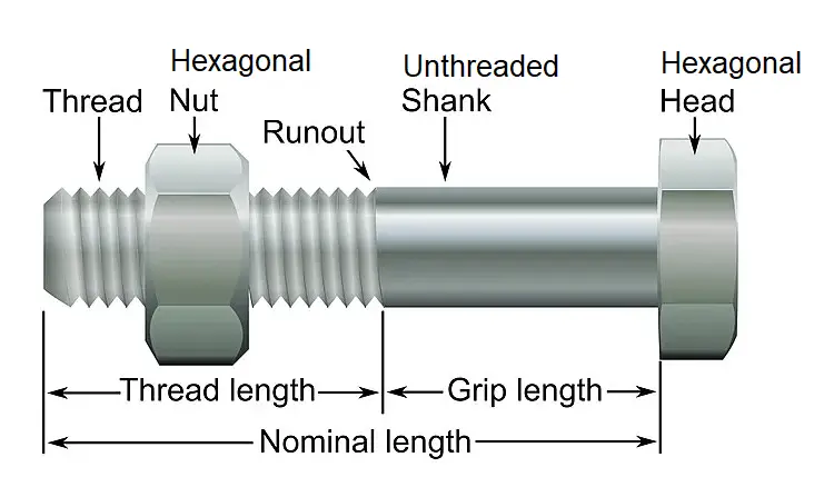
Hex Nuts:
A hex nut is a six-sided component with an internally threaded hole. When a hex bolt is inserted through parts that need to be fastened together, a hex nut is threaded onto the bolt from the opposite side. As the nut is tightened onto the bolt, it pulls the parts together, creating a secure connection. Note that using a hex nut with the hex bolt is not mandatory. In some cases, a secure connection can be achieved using only a hex bolt, particularly if the threaded hole into which the bolt is being inserted provides enough resistance to prevent the bolt from easily coming loose.
Washers:
A washer might also be used in conjunction with the hex nut and hex bolt. A washer is a flat, often circular, metal disc that is placed under the nut to distribute the load and reduce the risk of damaging the surface of the material being fastened.
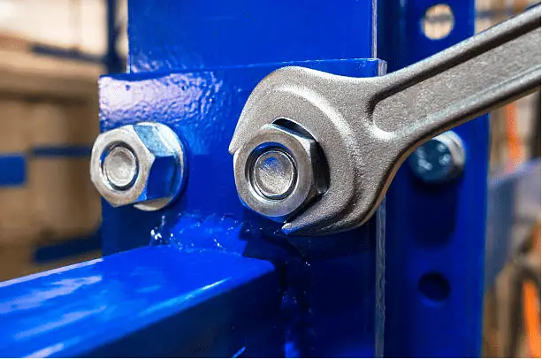
How Do Hex Bolts Work?
Depending on the application, hex bolts are used either in pre-tapped holes or along with nuts. A range of tools such as a hex bolt wrench, spanners, hex keys, socket sets, ratchet spanners, etc are used to tighten the bolt. The hexagonal head provides enough grip from various angles for the tool operator which eases the installation and removal process. Here’s how a hex bolt works (Fig. 2):
Threaded Shaft and Hexagonal Head:
Hex bolts have a threaded shaft with spiral grooves known as threads. These threads correspond to the threads in a compatible nut or threaded hole. The hexagonal head of the bolt is designed for easy gripping using a wrench or socket tool.
Insertion:
To use a hex bolt, you start by inserting the threaded end of the bolt through the parts you want to fasten together. The length of the bolt should be sufficient to accommodate the thickness of the materials being connected.
Hex Nut (Optional):
If you’re using a hex nut, you thread it onto the threaded shaft of the bolt from the opposite side of the materials. The hex nut is turned clockwise onto the threads, and as it moves along the shaft, it pulls the parts being fastened closer together.
Tightening:
Using a wrench or socket tool, you grip the hexagonal head of the bolt and rotate it clockwise to turn the bolt into the nut or threaded hole. As the bolt is turned, the threads of the bolt engage with the threads of the nut or threaded hole, causing the bolt to move forward.
Compression and Clamping Force:
As the bolt is tightened, it exerts an axial force on the connected parts. This axial force compresses the materials together, creating a clamping force that holds them in place. This compression ensures a secure and stable connection that resists movement and separation.
Locking Feature:
The resistance generated by the threads between the bolt and the nut or threaded hole provides a locking feature. This helps prevent the bolt from inadvertently loosening due to vibrations, impacts, or external forces.
Torque and Tightness:
The torque applied to the bolt determines the level of tightness achieved in the connection. Proper torque ensures that the fastened components are securely held together without damaging the materials or the threads. ASME PCC-1 provides a formula to calculate the required torque for bolting.
Adjustability and Removal:
The use of hex nuts allows for adjustability and ease of removal. If you need to disassemble the connection, you can simply reverse the rotation of the bolt to unthread it from the nut or threaded hole.
In summary, hex bolts work by threading the shaft into a compatible nut or threaded hole, creating axial force, and clamping the connected components together. The hexagonal head provides the necessary torque for tightening, and the threaded shaft and nut interaction prevents the connection from loosening over time.
Applications of Hex Bolts
Hex bolts find application in a myriad of industries and projects, ranging from construction to manufacturing. Some common applications include:
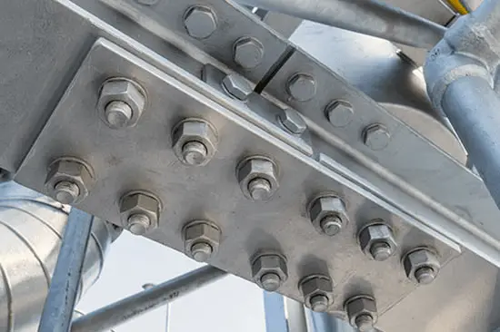
Construction:
Hex bolts are frequently used in construction for joining structural components (Fig. 3) like beams, columns, and trusses. They provide the necessary strength and stability to support heavy loads and ensure the safety of the structure.
Automotive and Machinery:
In the automotive and machinery industries, hex bolts are used to assemble engine components, chassis parts, and machinery frames. Their durability and strength are crucial for maintaining the integrity of these systems.
Furniture Assembly:
Hex bolts are often used in assembling furniture due to their ease of use and strong fastening capabilities. From bed frames to bookshelves, hex bolts provide the necessary stability for everyday use.
Infrastructure Projects:
Hex bolts play a role in large-scale infrastructure projects, such as bridges, tunnels, and railways, where their robustness is vital to ensure the safety and longevity of the structures.
Manufacturing:
Hex bolts are employed in manufacturing processes for assembling machinery, equipment, and production lines. They ensure that the parts are securely fastened together, preventing malfunction and improving overall operational efficiency.
Electronics:
In electronics manufacturing, hex bolts are utilized for securing components within equipment and devices. Their small size makes them suitable for applications where space is limited.
Aerospace and Aviation:
The aerospace industry relies on hex bolts for assembling aircraft components, engines, and critical systems. The high strength and reliability of hex bolts are crucial for ensuring the safety of air travel.
Renewable Energy Projects:
In solar panel installations and wind turbine construction, hex bolts are used to fasten frames, mounts, and structural components. Their resistance to environmental factors is important in outdoor applications.
Marine and Shipbuilding:
Hex bolts are essential for marine applications due to their resistance to corrosion in saltwater environments. They are used in shipbuilding, boat construction, and offshore structures.
Railways and Transportation:
Hex bolts are used in the construction and maintenance of railway tracks, bridges, and transportation infrastructure to ensure safety and stability.
Oil and Gas Industry:
Hex bolts are employed in the oil and gas sector for assembling equipment, pipelines, and infrastructure in both onshore and offshore facilities.
Communication Towers:
Hex bolts play a role in assembling communication towers, antennas, and transmission equipment to ensure stability and reliability.
Types of Hex Bolts
The types of hex bolts vary based on several factors such as size, material, threading, and head style.
Hex Bolt Types based on Threading
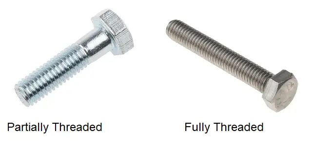
Based on the threading on the hex bolt, there are two types of hex bolts; Fully Threaded Hex Bolts and Partially Threaded Hex Bolts (Fig. 4).
- Fully Threaded Hex Bolts: These hex bolts have threading that spans the entire length of the shaft. They are used when maximum grip and clamping force are required, and they allow for more flexibility in adjusting the position of the nut along the bolt.
- Partially Threaded Hex Bolts: Partially thread hex bolts have threading that covers only a portion of the shaft, leaving an unthreaded shank below the head. These bolts are often used in situations where the unthreaded portion provides structural support or prevents the bolt from threading through a component.
Types of Hex Bolts based on the Head and Shaft Size
Based on the size of the head and shaft there are two types of hex bolts; Standard Hex Bolts and Heavy Hex Bolts.
- Standard Hex Bolts: A standard hex bolt, often simply referred to as a “hex bolt,” has a hexagonal head and a threaded shaft. The head size of a standard hex bolt is relatively smaller compared to a heavy hex bolt. This type of bolt is used in a wide range of applications where moderate strength and clamping force are required.
- Heavy Hex Bolts: A heavy hex bolt, also known as a “heavy hex head bolt,” has a larger head size and a thicker shank compared to a standard hex bolt. The larger head provides a larger bearing surface, distributing the load over a greater area and reducing the risk of material deformation or crushing. Heavy hex bolts are designed to provide higher strength and clamping force, making them suitable for applications that require greater reliability and durability.
Hex Bolt Types Depending on Bolt Materials
Hex bolts are manufactured using a variety of materials to suit different applications and environments. The choice of material depends on factors such as strength requirements, corrosion resistance, temperature conditions, and the specific industry in which the hex bolts will be used. Here are some common materials used for hex bolts:
Carbon Steel Hex Bolts:
Carbon steel hex bolts or simply steel hex bolts are widely used due to their affordability and general-purpose characteristics. They come in various grades, such as Grade 2, Grade 5, and Grade 8, each with increasing levels of tensile strength. Carbon steel bolts are suitable for non-corrosive environments and applications where moderate strength is sufficient.
Stainless Steel Hex Bolts:
Stainless steel hex bolts are popular for their excellent corrosion resistance. They are particularly useful in outdoor, marine, and food-related applications where exposure to moisture and harsh conditions is a concern. Common stainless steel grades used for hex bolts include 18-8 (or 304), 316, and 316L.
Alloy Steel Hex Bolts:
Alloy steel hex bolts are alloyed with additional elements to enhance their mechanical properties, such as strength and hardness. These bolts are used in applications that require high tensile strength and resistance to wear and abrasion. Grades such as ASTM A193 B7 and ASTM A325 are examples of alloy steel bolts used in structural and heavy-duty applications.
Brass Hex Bolts:
Brass hex bolts offer corrosion resistance, good electrical conductivity, and an attractive appearance. They are often used in decorative applications, electronics, and plumbing, where corrosion prevention and aesthetics are important.
Bronze Hex Bolts:
Bronze hex bolts are valued for their corrosion resistance, particularly in marine environments. They are used in applications where high strength and resistance to saltwater corrosion are necessary.
Titanium Hex Bolts:
Titanium hex bolts are lightweight, strong, and corrosion-resistant. They are used in applications where weight reduction, high strength, and resistance to chemical environments are critical, such as aerospace and medical equipment.
Galvanized Steel Hex Bolts
Galvanized hex bolts have a zinc coating that provides a layer of protection against corrosion. They are commonly used in outdoor and construction applications.
Aluminum Hex Bolts:
Aluminum hex bolts are lightweight and corrosion-resistant. They find use in applications where weight reduction and resistance to corrosion are priorities.
Nylon Hex Bolts:
Nylon hex bolts are non-metallic and are used in applications where electrical insulation, low friction, and non-magnetic properties are important.
Plastic Hex Bolts:
Plastic hex bolts, made from various thermoplastic materials, are used in applications that require resistance to chemicals, electrical insulation, and non-corrosive properties.
Even though hexagonal bolts from a wide range of material options are available, Steel and Stainless steel hex bolts are the most widely used bolts in the construction industry. Carbon steel hex bolts are usually produced based on ASTM A307, ASTM F3125, and ASTM A449 specifications. On the other hand, stainless steel hex bolts are manufactured based on ASTM A320, ASTM A193, ASTM A437, and ASTM A453 specifications.
Additional coating and finishes are added to the steel hex bolts for increasing the life of the bolt. Common hex bolt finishes are:
- Bright zinc-plated
- Hot dip Galvanized Zinc hex bolt
- Clear passivated
- Black oxide
- Cadmium Plating
- Chrome Plating
- Nickel Plating, etc
Hex Bolt Sizes
Hex bolts come in a wide range of sizes to accommodate different applications and requirements. The size of a hex bolt is determined by its diameter, length, and thread pitch. Hex bolt sizes are typically specified using measurements in inches or millimeters, depending on the region and standard used. Here’s a general overview of hex bolt sizes:
- Diameter: The diameter of a hex bolt refers to the thickness of the bolt shaft, excluding the threads. It’s commonly measured across the flat sides of the hexagonal head. Common diameter sizes for hex bolts include 1/4″, 3/8″, 1/2″, 5/8″, 3/4″, 7/8″, 1″, and larger.
- Length: The length of a hex bolt is measured from the bottom of the head to the end of the threaded shaft. Hex bolts are available in various lengths to accommodate different material thicknesses and applications.
- Thread Pitch: Thread pitch refers to the distance between adjacent threads on the bolt’s threaded shaft. It is measured in threads per inch (TPI) for inch-sized bolts and in millimeters for metric-sized bolts.
- Threads: Hex bolts can have either coarse threads or fine threads. Coarse threads have fewer threads per inch, making them quicker to install and more suitable for applications where rapid assembly is required. Fine threads have more threads per inch and offer greater precision in adjustment.
The ISO metric thread size system provides a handy international standard for measuring thread sizes across an array of different screw and bolt types and as such is widely used around the world. The hex bolt size is denoted by the letter ‘M’ followed by a number that indicates the outer diameter of the thread, measured in millimeters. As an example, a hex bolt with a thread size of M16 would have an outer diameter of 16 mm.
Hex Bolt Size Chart
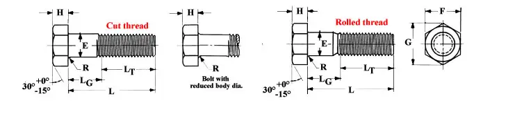
Hex bolt dimensions are provided by ASME B18.2.1. Table 1 below provides the Hex bolt dimension chart for inch series bolts and screws based on ASME B18.2.1. Refer to this hex bolt dimension chart along with the Image in Fig. 5.
| Hex Bolt Dimensions (ANSI B18.2.1-2012)– Inch Series | |||||||||||||||
| Nominal Size | Basic Product Diameter | Body Diameter E | Width Across Flat (F) | Width Across Corners (G) | Head Height (H) | Radius of Fillet (R) | Thread Length (LT) | ||||||||
| Max | Min | Basic | Max | Min | Max | Min | Basic | Max | Min | Max | Min | Basic (6 in. and shorter) | Basic (Over 6 in.) | ||
| 1/4 | 0.2500 | 0.26 | 0.237 | 7/16 | 0.438 | 0.425 | 0.505 | 0.484 | 11/64 | 0.188 | 0.15 | 0.03 | 0.01 | 0.75 | 1 |
| 5/16 | 0.3125 | 0.324 | 0.298 | 1/2 | 0.5 | 0.484 | 0.577 | 0.552 | 7/32 | 0.235 | 0.195 | 0.03 | 0.01 | 0.875 | 1.125 |
| 3/8 | 0.3750 | 0.388 | 0.36 | 9/16 | 0.562 | 0.544 | 0.65 | 0.62 | 1/4 | 0.268 | 0.226 | 0.03 | 0.01 | 1 | 1.25 |
| 1/2 | 0.5 | 0.515 | 0.482 | 3/4 | 0.75 | 0.725 | 0.866 | 0.826 | 11/32 | 0.364 | 0.302 | 0.03 | 0.01 | 1.25 | 1.5 |
| 5/8 | 0.625 | 0.642 | 0.605 | 15/16 | 0.938 | 0.906 | 1.083 | 1.033 | 27/64 | 0.444 | 0.378 | 0.06 | 0.02 | 1.5 | 1.75 |
| 3/4 | 0.75 | 0.768 | 0.729 | 1. 1/8 | 1.125 | 1.088 | 1.299 | 1.24 | 1/2 | 0.524 | 0.455 | 0.06 | 0.02 | 1.75 | 2 |
| 7/8 | 0.875 | 0.895 | 0.852 | 1. 5/16 | 1.312 | 1.269 | 1.516 | 1.447 | 37/64 | 0.604 | 0.531 | 0.06 | 0.02 | 2 | 2.25 |
| 1 | 1.0 | 1.022 | 0.976 | 1. 1/2 | 1.5 | 1.45 | 1.732 | 1.653 | 43/64 | 0.7 | 0.591 | 0.09 | 0.03 | 2.25 | 2.5 |
| 1 1/8 | 1.125 | 1.149 | 1.098 | 1 11/16 | 1.688 | 1.631 | 1.949 | 1.859 | 3/4 | 0.78 | 0.658 | 0.09 | 0.03 | 2.5 | 2.75 |
| 1 1/4 | 1.25 | 1.277 | 1.223 | 1 7/8 | 1.875 | 1.812 | 2.165 | 2.066 | 27/32 | 0.876 | 0.749 | 0.09 | 0.03 | 2.75 | 3 |
| 1 3/8 | 1.375 | 1.404 | 1.345 | 2 1/16 | 2.062 | 1.994 | 2.382 | 2.273 | 29/32 | 0.94 | 0.81 | 0.09 | 0.03 | 3 | 3.25 |
| 1 1/2 | 1.5 | 1.531 | 1.47 | 2 1/4 | 2.25 | 2.175 | 2.598 | 2.48 | 1 | 1.036 | 0.902 | 0.09 | 0.03 | 3.25 | 3.5 |
| 1 5/8 | 1.625 | 1.658 | 1.591 | 2 7/16 | 2.438 | 2.356 | 2.815 | 2.616 | 1 3/32 | 1.116 | 0.978 | 0.09 | 0.03 | 3.5 | 3.75 |
| 1 3/4 | 1.75 | 1.785 | 1.716 | 2 5/8 | 2.625 | 2.538 | 3.031 | 2.893 | 1 5/32 | 1.196 | 1.054 | 0.12 | 0.04 | 3.75 | 4 |
| 1 7/8 | 1.875 | 1.912 | 1.839 | 2 13/16 | 2.812 | 2.719 | 3.248 | 3.099 | 1 1/4 | 1.276 | 1.13 | 0.12 | 0.04 | 4 | 4.25 |
| 2 | 2 | 2.039 | 1.964 | 3 | 3 | 2.9 | 3.464 | 3.306 | 1 11/32 | 1.388 | 1.175 | 0.12 | 0.04 | 4.25 | 4.5 |
| 2 1/4 | 2.25 | 2.305 | 2.214 | 3 3/8 | 3.375 | 3.262 | 3.897 | 3.719 | 1 1/2 | 1.548 | 1.327 | 0.19 | 0.06 | 4.75 | 5 |
| 2 1/2 | 2.5 | 2.559 | 2.461 | 3 3/4 | 3.75 | 3.625 | 4.33 | 4.133 | 1 21/32 | 1.708 | 1.479 | 0.19 | 0.06 | 5.25 | 5.5 |
| 2 3/4 | 2.75 | 2.827 | 2.711 | 4 1/8 | 4.125 | 3.988 | 4.763 | 4.546 | 1 13/16 | 1.869 | 1.632 | 0.19 | 0.06 | 5.75 | 6 |
| 3 | 3 | 3.081 | 2.961 | 4 1/2 | 4.5 | 4.35 | 5.196 | 4.959 | 2 | 2.06 | 1.815 | 0.19 | 0.06 | 6.25 | 6.5 |
| 3 1/4 | 3.25 | 3.335 | 3.21 | 4 7/8 | 4.875 | 4.712 | 5.629 | 5.372 | 2 3/16 | 2.251 | 1.936 | 0.19 | 0.06 | 6.75 | 7 |
| 3 1/2 | 3.5 | 3.589 | 3.461 | 5 1/4 | 5.25 | 5.075 | 6.062 | 5.786 | 2 5/16 | 2.38 | 2.057 | 0.19 | 0.06 | 7.25 | 7.5 |
| 3 3/4 | 3.75 | 3.858 | 3.726 | 5 5/8 | 5.625 | 5.437 | 6.495 | 6.198 | 2 1/2 | 2.572 | 2.241 | 0.19 | 0.06 | 7.75 | 8 |
| 4 | 4 | 4.111 | 3.975 | 6 | 6 | 5.8 | 6.928 | 6.612 | 2 11/16 | 2.764 | 2.424 | 0.19 | 0.06 | 8.25 | 8.5 |
Table 2 below provides the size chart for hex bolts as per DIN 931.
| Thread Size | Thread Diameter | Threaded Shank Length (up to 125mm) | Threaded Shank Length (125-200mm) | Threaded Shank Length (200+mm) | Head Width | Thread Width |
|---|---|---|---|---|---|---|
| M4 | 0.7 | 14mm | n/a | n/a | 2.8 | 7 |
| M5 | 0.8 | 16mm | 22mm | n/a | 3.5 | 8 |
| M6 | 1 | 18mm | 24mm | n/a | 4 | 10 |
| M8 | 1.25 | 22mm | 28mm | n/a | 5.3 | 13 |
| M10 | 1.5 | 26mm | 32mm | 45mm | 6.4 | 17 |
| M12 | 1.75 | 30mm | 36mm | 49mm | 7.5 | 19 |
| M14 | 2 | 34mm | 40mm | 53mm | 8.8 | 22 |
| M16 | 2 | 38mm | 44mm | 57mm | 10 | 24 |
| M20 | 2.5 | 46mm | 52mm | 65mm | 12.5 | 30 |
Benefits of Using Hex Bolts
The popularity of hex bolts can be attributed to several key benefits:
- Secure Fastening: The threading and design of hex bolts ensure a strong and secure connection between components, preventing loosening or shifting over time.
- Versatility: Hex bolts come in various sizes, materials, and coatings, making them versatile enough to suit a wide range of applications.
- Ease of Installation: The hexagonal head of the bolt allows for easy gripping and turning, which simplifies the installation process.
- Durability: Depending on the material and coating, hex bolts can resist corrosion, ensuring they maintain their strength and integrity in various environments.
Conclusion
Hex bolts are a fundamental element of the fastening world, providing strength, reliability, and security across countless industries and projects. With their distinct features, wide-ranging applications, and numerous benefits, hex bolts continue to be the preferred choice for those seeking to create durable and resilient connections. Whether you’re constructing a building, assembling machinery, or working on a DIY project, hex bolts are the steadfast solution for achieving secure and long-lasting connections.