Fasteners are the unsung heroes of the industrial world, holding together everything from bridges to bicycles. However, in dynamic and demanding environments, traditional nuts and bolts can sometimes come loose, leading to costly maintenance and safety concerns. This is where lock nuts come into play. Lock nuts are an essential component in ensuring the stability and security of various structures and machinery. In this article, we’ll delve into the world of lock nuts, exploring what they are, how they work, and their diverse applications.
What Are Lock Nuts?
Lock nuts, also known as locking nuts or self-locking nuts, are a special type of mechanical fasteners designed to resist vibrations, shocks, and other forces that can cause traditional nuts to loosen over time. They accomplish this by employing various mechanisms that provide additional friction or resistance, preventing the nut from turning unintentionally.
Also known as stiffnuts, Locknuts are screwed onto a bolt or threaded rod just like standard nuts, but they provide a secure fixing. With the invention of locknuts in the 1930s, the expense for secure connection was reduced a lot, as earlier two standard nuts were used for preventing the loosening of nuts due to vibration or shocks. Individual lock nuts are costly as compared to standard nuts but they are a cheaper option compared to buying two standard nuts.
How Do Lock Nuts Work?
There are two modes of working by which lock nuts provide a secure connection.
Using Friction between the Mating Threads:
Lock nuts work by increasing the friction between the nut and the bolt threads. This friction is essential in preventing self-loosening, a common problem in many applications. When vibrations or external forces act on a traditional nut, they can cause it to rotate slightly in the opposite direction, leading to loosening. Lock nuts resist this motion, ensuring that the nut remains securely fastened.
Using a Positive Locking Device:
Some lock nuts have special threading designs that can include pitted or flanged grooves. They are basically nuts with positive locks.
Types of Lock Nuts
Broadly there are two categories of lock nuts; prevailing torque nuts and surface-bearing lock nuts.
Prevailing Lock Nuts
Prevailing Torque Nuts use a specialized design that adds resistance to the turning (torque) of the nut. This design might include flanges or serrations that grip the threads more tightly as pressure is applied. The prevailing torque denotes the required force to have a tight grip such that it does not back off easily.
Some examples of prevailing torque lock nuts are:
- Conical lock nuts,
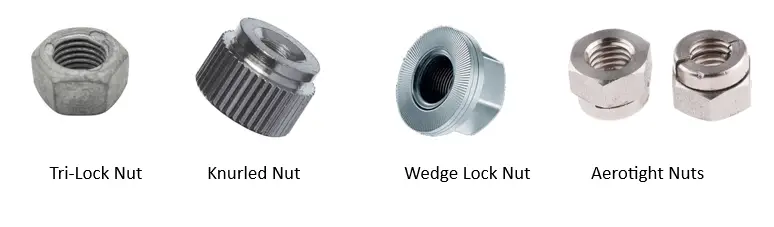
- Tri-lock nuts,
- Top lock,
- Stover lock nut, and
- Griptite nuts.
They are metallic metal lock nuts. Some of them may have some sort of lip or crown that is designed to be crimped around a bolt shaft after installation. This crimping process is what creates enough prevailing torque to hold the lock nut in place, even during heavy vibration.
Surface Bearing Lock Nuts
A surface-bearing locking nut can be tightened against a bearing surface to activate a locking mechanism that secures it firmly in place. Often they are designed with an integrated washer-like flange at one end. This flange serves multiple purposes:
- Distribution of Load
- Locking Mechanism
- Proper Alignment
The most widely used locknut types are described below:
Nylon Insert Lock Nuts:
Nylon insert lock nuts, also known as nylon nuts or Nyloc Nuts, have a nylon ring embedded in the top of the threads. When tightened, the nylon ring deforms to grip the threads, providing resistance to vibration and preventing the nut from loosening unintentionally. These are the most common type of lock nuts with a tight grip on the threads of the bolt.
Hex Jam Nuts:
Hex jam nuts are thin, low-profile nuts with the same thread size and pitch as a standard hex nut. They are often used as a secondary nut to lock the position of a primary nut or to reduce the clearance between two fasteners.

Stover Locking Nuts:
Stover locking nuts are designed with a unique, free-spinning collar on the top. When the nut is tightened, the collar bites into the threads, creating resistance to rotation and preventing self-loosening.
Center Locknuts:
Center locknuts, also called crimping locknuts, have a central groove that can be crimped or deformed after tightening to secure the nut in place.
Serrated Flange Lock Nuts:
Serrated flange lock nuts have an integrated washer-like flange with serrations on the underside. These serrations grip the surface and resist vibration, making them self-locking.
Jet Nuts or K-Lock Nuts:
Jet nuts sometimes referred to as K-lock nuts, have a unique design with multiple thin slots cut into the top surface. These slots create tension that prevents the nut from loosening.
Castle-Lock Nuts:
Castle-lock nuts, also known as castellated nuts, have slots or notches cut into the top surface, resembling the turrets of a castle. These slots are used in conjunction with a cotter pin or a split pin to secure the nut in place.
Tri-Lock Nuts:
Tri-lock nuts, also called triple-lock nuts, have three locking elements or lobes on the top surface. These elements provide extra resistance to loosening, making them suitable for high-vibration applications.
All-Metal Lock Nuts:
All-metal lock nuts, as the name suggests, do not have any non-metallic components like nylon inserts. They rely on unique thread designs or deformation of the threads to create locking action. These nuts are often used in high-temperature or corrosive environments where nylon inserts may not be suitable.
Wedge Lock Nuts:
Wedge lock nuts feature a unique design with one or more wedges or cams built into the nut. When the nut is tightened, these wedges or cams engage with the threads, creating a strong, mechanical lock that resists loosening. Wedge lock nuts are commonly used in applications where reliability and resistance to vibration are crucial.
Knurled Nuts:
Knurled nuts have a textured or ridged outer surface, known as knurling, instead of a smooth surface. The knurling provides a better grip for manual tightening and loosening, making them suitable for applications where tools may not be readily available or where hand adjustment is preferable. Knurled nuts are often used in electronics, instrumentation, and other applications where precise adjustments are required.
Slotted Nuts:
Slotted nuts have slots or notches cut into the top surface. These slots are designed to accommodate a cotter pin or a split pin, which is inserted through the slots and bent to secure the nut in place. Slotted nuts are commonly used in applications where it’s critical to prevent the nut from unintentionally loosening, such as in automotive and machinery applications. They look exactly like Castle nuts with the only difference being that slotted nuts are shorter than castle nuts with the same thread size.
Aerotight Nuts:
“Aerotight” is a brand name for a specific type of prevailing torque lock nut. Prevailing torque lock nuts, including Aerotight nuts, are designed to provide resistance to vibration and self-loosening. They achieve this by incorporating a special locking feature, often a collar or deformation in the threads, that creates friction and resistance when the nut is tightened. Aerotight nuts are commonly used in aerospace and aviation applications where reliability and safety are paramount.
Philidas Nut:
The Philidas nut is a type of lock nut manufactured by Philidas Ltd, a company based in Pontefract, West Yorkshire, England.
Plate Nut:
A plate nut is a stamped sheet metal nut that is usually riveted to a workpiece. They have a long tube that is internally threaded and a plate with two clearance holes for rivets. The most popular versions have two lugs and they exist as fixed anchor nuts and as floating anchor nuts.
Security Locknut:
A security locknut is composed of two steel threaded parts: a nut body and an elliptical spring steel lock ring. They are fastened onto a mating bolt to form a bolted joint.
Speed Nut:
A speed nut, also known as a spring nut or sheet metal nut, is typically used in applications where rapid assembly is required. It features a spring-like design that grips onto panels or sheet metal when installed, eliminating the need for additional hardware.
Locking Nuts Grades and Finishes
Locknuts are manufactured in several different grades and finishes. The common lock nut material grades are
ASTM A194 – Standard Specification for Carbon and Alloy Steel Nuts for Bolts for High-Pressure or High-Temperature Service, or Both: ASTM A194 covers various grades of carbon and alloy steel nuts for use with bolts in high-pressure or high-temperature applications. These nuts include heavy hex nuts, square nuts, and heavy hex structural nuts. The material grades specified in ASTM A194 include Grade 2H, Grade 2HM, Grade 4, Grade 7, Grade 7M, Grade 8, and Grade 8M.
ASTM A563 – Standard Specification for Carbon and Alloy Steel Nuts: ASTM A563 covers carbon and alloy steel nuts that are not covered in ASTM A194. This standard includes several grades, such as Grade A, Grade B, Grade C, and Grade DH, which differ in terms of mechanical properties and applications.
ASTM F467 – Standard Specification for Nonferrous Nuts for General Use: ASTM F467 specifies various grades of nonferrous (non-iron) nuts for general use. This standard covers materials such as copper, copper alloys, aluminum, and more. It includes specifications for hex nuts, square nuts, and other types of nuts.
ASTM B348 – Standard Specification for Titanium and Titanium Alloy Bars and Billets: ASTM B348 is referenced when specifying titanium alloy lock nuts, particularly in high-performance and aerospace applications.
ASTM D4066 is relevant when specifying the material properties of nylon insert lock nuts, which are commonly used to provide resistance to vibration and self-loosening.
Lock nuts, like other fasteners, can have various finishes applied to them for both functional and aesthetic purposes. These finishes help improve the performance and durability of the nuts in different environments and applications. Here are some common lock nut finishes:
- Galvanized Lock Nuts (Hot dip galvanizing)
- Plated Lock Nuts (Zinc plating, Nickel plating, Cadmium plating)
- Passivation
- Anodizing, etc
How to Specify Locknuts
The locking nuts must be specified based on the following parameters:
- Thread direction – lock nuts are available with clockwise (right-hand) or anticlockwise (left-hand) threading
- Locknut sizes- Specify the required size of locknut in metric or imperial standards
- The type of Locknut depending on the application.
- Material of Locknut
- Any secondary components such as a specific washer, to lock properly requirements
Application of Lock Nuts
Locknuts are found to be used in various industries as mentioned below:
- Automotive Industry: Lock nuts are extensively used in the automotive industry to secure critical components such as wheels, axles, and engine parts. Their ability to withstand the constant vibrations and shocks associated with vehicles is crucial for safety.
- Construction: In construction, lock nuts are used in various applications, including securing scaffolding, reinforcing bars (rebar), and structural connections. They ensure that critical connections remain stable over time.
- Machinery and Manufacturing: Lock nuts are found in industrial machines and manufacturing equipment to secure parts that undergo high levels of vibration, such as conveyor belts and rotating machinery.
- Aerospace: In the aerospace industry, where precision and reliability are paramount, lock nuts are used to secure critical components like aircraft engines and landing gear.
- Marine Industry: Lock nuts are used in marine applications to secure components like propellers and engine mounts, where exposure to moisture and constant motion can lead to traditional fasteners loosening.
Refer to the following table that explains the types of lock nuts used in various industries.
| Applications | Lock Nut Types | |||||
| Self-locking flange hex nuts | Jam nuts | Castle nuts | Slotted nuts | Nyloc nuts | Stover nuts | |
| Construction | X | |||||
| Metalworking | X | X | ||||
| Electronics/Computing | X | X | X | |||
| Furniture | X | X | ||||
| Pipelines | X | X | ||||
| Air and Rail | X | X | ||||
| Specialty equipment and vehicles | X | X | X | |||
| Automotive | X | X | X | X | ||
Lock Nut Sizes
Lock nuts, like other types of nuts, come in various sizes to accommodate different bolt or screw diameters and thread pitches. The size of a lock nut is typically described using two main parameters: the nominal diameter (often referred to as the “size”) and the thread pitch. Here’s how these parameters are typically specified:
- Nominal Diameter (Size): This refers to the major diameter of the threads on the bolt or screw with which the nut is intended to be used. The nominal diameter is commonly expressed in either metric units (millimeters) or imperial units (inches). For example, a metric lock nut might have a nominal diameter of M10 (indicating a 10-millimeter diameter), while an imperial nut might be designated as 3/8″ (indicating a 3/8-inch diameter).
- Thread Pitch: The thread pitch specifies the distance between adjacent threads on the bolt or screw. It is also expressed in metric or imperial units. For example, an M10 x 1.5 lock nut means that it is designed for a 10-millimeter nominal diameter bolt with a thread pitch of 1.5 millimeters. Similarly, a 3/8″-16 lock nut corresponds to a 3/8-inch nominal diameter bolt with 16 threads per inch.
Common locknut thread sizes are M3, M4, M5, M6, M8, M10, M12, M16, and M20.
Differences Between a Lock Nut and a Lock Washer
Here’s a table summarizing the key differences between a lock washer and a lock nut:
| Characteristic | Lock Washer | Lock Nut |
|---|---|---|
| Purpose | Prevents nut or bolt from loosening due to vibration or torque | Prevents the nut from loosening due to vibration or torque |
| Type | External tooth lock washer, internal tooth lock washer, split washer, etc. | Nylon insert lock nut, prevailing torque lock nut, flange lock nut, etc. |
| Location | Placed between the nut/bolt head and the surface | Replace the standard nut; installed directly on the bolt |
| Mechanism | Creates friction by serrations or deformation when compressed | Uses various mechanisms like nylon inserts, flanges, serrations, or prevailing torque designs to create resistance against loosening |
| Reusability | Typically one-time use; must be replaced when removed | Can be reused multiple times without losing its locking properties |
| Aesthetic | Usually not visible after installation | Visible and comes in various styles and finishes |
| Ease of Installation | Requires additional installation step | Installed like a regular nut |
| Common Applications | General fastening needs where a nut and bolt are used | Situations where a specific type of locking mechanism is needed, such as automotive or machinery applications |