When it comes to piping, plumbing, and fluid systems, ensuring a secure and leak-free connection is highly important. One crucial component that plays a significant role in achieving this goal is the bulkhead fitting. A bulkhead is a special pipe fitting to allow the free liquid flow from a tank, drum drainage, reservoir, or other plumbing systems through a hole. They are found to be installed in various piping systems as distribution outlets. Understanding bulkhead fittings is essential for maintaining the integrity of the fluid systems. In this comprehensive guide, we’ll delve into what bulkhead fittings are, how they work, their types, and their various applications.
What Are Bulkhead Fittings?
A bulkhead fitting or bulkhead pipe fitting is a specialized threaded connector designed to provide a leak-proof and structurally sound passage through a barrier. This barrier can be a wall, tank, reservoir, or any other surface that separates two areas where fluid transfer or containment is necessary. Bulkhead fittings are commonly used in plumbing, piping, industrial processes, automotive applications, and even in aquariums.
They can be used with unions or male adaptors. Their left-handed threads help the bulkhead fitting to be intact and tight while installing the male adapter. While used with unions, bulkhead pipe fittings easily remove content from pumps and accessories. They are also available with nuts and gaskets as accessories which are usually purchased separately.
Components of a Bulkhead Fitting
Bulkhead fittings consist of several key components:
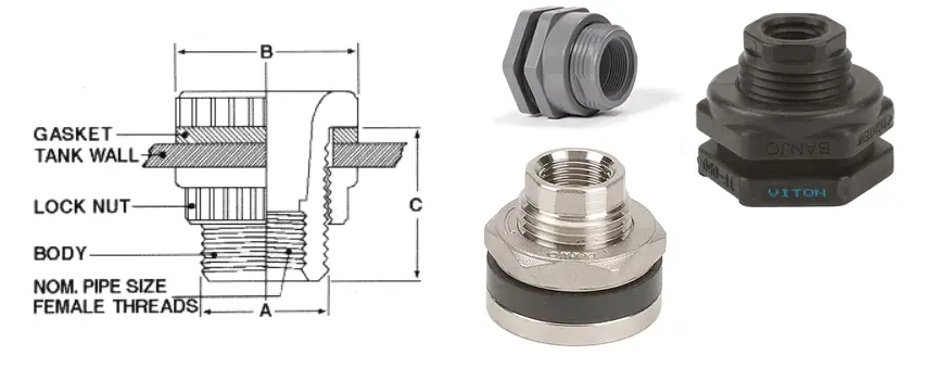
Body: This is the central piece that passes through the barrier. It often has threads on both ends for attaching nuts and gaskets or O-rings to create a watertight seal.
Nuts: There are two nuts in a bulkhead fitting—one on each side of the barrier. These nuts are tightened against the barrier to secure the fitting in place.
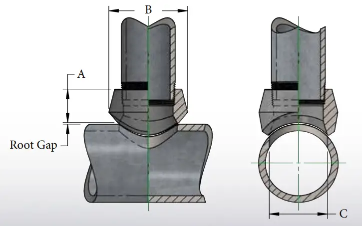
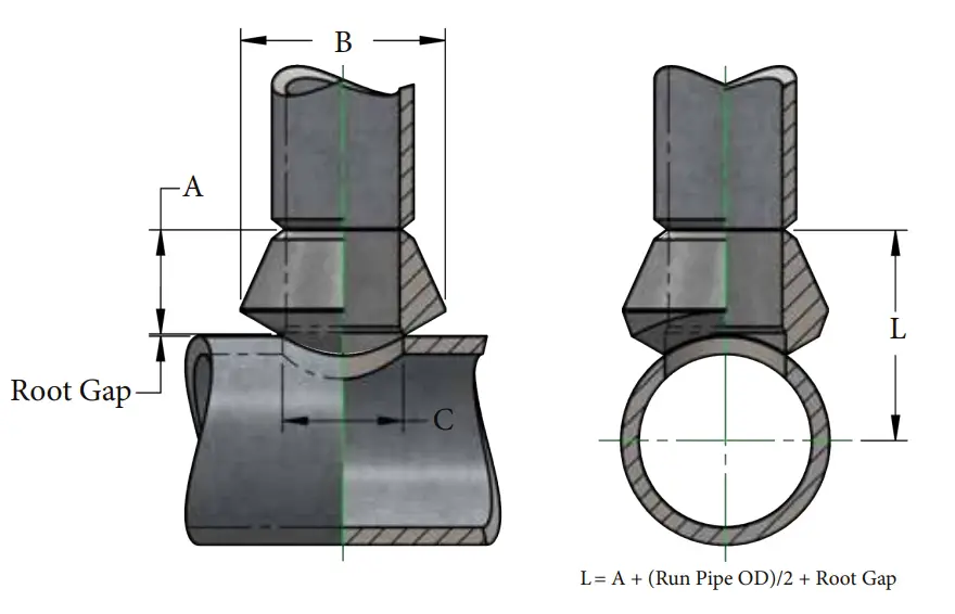
Gasket or O-ring: Placed between the nuts and the barrier, this component ensures a tight seal, preventing leaks. Refer to Fig. 1 which shows the major components of a typical bulkhead fitting.
How Do Bulkhead Fittings Work?
The working principle of bulkhead fittings is quite simple:
- Drill a hole of the appropriate size in the barrier where you want to install the bulkhead fitting.
- Insert the threaded body of the fitting through the hole.
- Place a gasket or O-ring on each side of the barrier.
- Screw on the nuts, one on each side, and tighten them securely.
- The pressure from tightening the nuts compresses the gaskets or O-rings against the barrier, creating a watertight seal.
Types of Bulkhead Fittings
Bulkhead fittings come in various types, each suited to specific applications:
- Standard Bulkhead Fittings: These are the most common type and are used for general fluid transfer applications.
- Tank Bulkhead Fittings: Designed for use with tanks, these often have larger diameter bodies and are used to create inlets or outlets for liquids in storage containers.
- Flanged Bulkhead Fittings: These are fitted with flanges instead of nuts, providing additional stability and support. They are commonly used in high-pressure applications.
- Double-Bulkhead Fittings: These fittings allow for a connection on both sides of the barrier, which can be useful in certain plumbing configurations.
- Bulkhead Valves: These fittings incorporate a valve component, allowing for control of fluid flow through the barrier.
Again based on the installation connection bulkhead fittings can be categorized into two groups; Threaded Bulkhead Fittings, and Slip Bulkhead Fittings.
Threaded Bulkhead Fittings:
Threaded bulkhead fittings are a type of bulkhead fitting designed with threaded ends that allow them to be securely attached to pipes, tanks, or other components on both sides of a barrier, such as a wall or tank wall. These fittings typically consist of a threaded body, two nuts, and gaskets or O-rings. To install a threaded bulkhead fitting, a hole is drilled through the barrier, and the threaded body is passed through it. Nuts are then tightened onto the threaded ends of the body on each side of the barrier, compressing gaskets or O-rings to create a watertight seal. Threaded bulkhead fittings are commonly used in plumbing, industrial applications, and fluid systems where a threaded connection is required for a secure and leak-proof passage through a barrier.
Slip Bulkhead Fittings:
Slip bulkhead fittings, also known as slip-style bulkhead fittings, are a type of bulkhead fitting that does not have threaded ends. Instead, they have smooth or “slip” ends, and they rely on solvent welding or adhesive bonding to create a secure and leak-proof connection. To install a slip bulkhead fitting, a hole is drilled through the barrier, and the smooth ends of the fitting are inserted into the holes. Solvent cement or adhesive is then applied to the joints between the fitting and the barrier on both sides, forming a chemical bond that fuses the components together. Slip bulkhead fittings are often used in applications where threaded connections may not be practical or where a cleaner, more streamlined appearance is desired, such as in PVC or CPVC plumbing systems, particularly in aquariums and water treatment systems.
Materials for Bulkhead Pipe Fittings
Bulkhead fittings are used in a variety of industries and applications, and the choice of materials for these fittings depends on factors such as the type of fluid being conveyed, the operating conditions, and the compatibility with the surrounding environment. Here are some common materials used for bulkhead fittings:
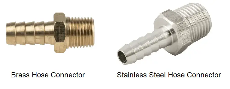
Brass Bulkhead Fittings:
Brass bulkhead fittings are corrosion-resistant and well-suited for applications involving water, air, and non-aggressive chemicals. They are commonly used in plumbing and pneumatic systems.
Stainless Steel Bulkhead Fittings:
Stainless steel bulkhead fittings are highly corrosion-resistant and suitable for a wide range of fluids, including corrosive chemicals and high-temperature liquids. They are often used in industrial and marine applications.
Aluminum Bulkhead Fittings:
Aluminum bulkhead fittings are lightweight and corrosion-resistant, making them a good choice for applications where weight is a concern, such as in the automotive and aerospace industries.
Plastic Bulkhead Fittings:
Plastic bulkhead fittings, typically made from materials like PVC, CPVC, or polypropylene, are lightweight and resistant to corrosion. They are commonly used in applications involving water, acids, and certain chemicals. They are often used in aquariums, water treatment, and chemical handling.
Nylon Bulkhead Fittings:
Nylon bulkhead fittings are lightweight, durable, and resistant to many chemicals. They are commonly used in fluid systems where chemical resistance and non-corrosiveness are important.
PVDF (Polyvinylidene Fluoride) Bulkhead Fittings:
PVDF bulkhead fittings are known for their excellent chemical resistance, especially to highly corrosive chemicals. They are often used in chemical processing and semiconductor manufacturing.
Copper Bulkhead Fittings:
Copper bulkhead fittings are used in specific applications where the advantages of copper, such as excellent thermal conductivity, are required. They are more commonly used in plumbing systems.
Bronze Bulkhead Fittings:
Bronze bulkhead fittings are known for their strength and corrosion resistance. They are used in marine applications, such as boat plumbing, where exposure to saltwater is a concern.
Nickel-Plated Brass Bulkhead Fittings:
Nickel-plated brass bulkhead fittings combine the corrosion resistance of brass with the added protection of a nickel coating. They are often used in environments where both corrosion resistance and aesthetics are important.
Hastelloy Bulkhead Fittings:
Hastelloy bulkhead fittings are used in extremely corrosive environments, including those with high concentrations of acids and chemicals. They are commonly used in chemical processing and the oil and gas industry.
When selecting the material for a bulkhead fitting, it’s essential to consider factors like the type of fluid being transported, temperature and pressure requirements, the environment in which the fitting will be installed, and compatibility with other materials in the system. Additionally, it’s crucial to follow industry standards and guidelines for material selection to ensure the safe and reliable operation of the fluid system.
Applications of Bulkhead Fittings
Bulkhead fittings find application in a wide range of industries:
- Industrial Processes: In industrial settings, bulkhead fittings are crucial for connecting pipes and tanks, especially in chemical processing and manufacturing.
- Plumbing: They are used to connect pipes through walls or floors, maintaining the integrity of plumbing systems.
- Aquariums: Bulkhead fittings are used to create watertight connections in aquariums for water circulation and filtration systems.
- Automotive: Bulkhead fittings can be found in fuel lines and brake systems in vehicles.
- Agriculture: These fittings are used in irrigation systems and liquid storage tanks on farms.
- Marine: Bulkhead fittings are vital for maintaining the watertight integrity of ships and boats.
Definitions of Frequently Asked Terms
Bulkhead Fitting PVC: A bulkhead fitting made from polyvinyl chloride (PVC) material. These fittings are often used in PVC plumbing systems and are designed to provide a secure and watertight connection through a PVC barrier.
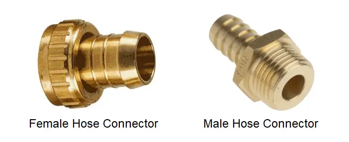
Barb Bulkhead Fitting: A bulkhead fitting with barbed ends that are used to connect flexible hoses or tubing securely through a barrier. These fittings are commonly used in fluid systems where a flexible connection is required.
Hydraulic Bulkhead Fitting: A bulkhead fitting specifically designed for hydraulic systems. These fittings are constructed to withstand high-pressure hydraulic fluids and maintain a leak-free connection through a barrier.
Bulkhead Fitting Stainless Steel: A bulkhead fitting made from stainless steel, known for its corrosion resistance and durability. Stainless steel bulkhead fittings are often used in applications where resistance to corrosion is crucial.
Garden Hose Bulkhead Fitting: A bulkhead fitting designed for garden hoses, typically used to create a watertight connection through a wall or container for outdoor watering or irrigation systems.
Water Tank Bulkhead Fitting: A type of bulkhead fitting used in water storage tanks to establish a connection for filling, draining, or monitoring the tank’s water levels.
Fuel Tank Bulkhead Fitting: A bulkhead fitting designed for fuel tanks, commonly used in automotive and marine applications to create secure connections for fuel lines or fuel level sensors.
Bulkhead Fitting Rain Barrel: A bulkhead fitting used in rain barrels to allow for controlled filling or drainage, often used in eco-friendly rainwater harvesting systems.
Fuel Bulkhead Fitting: A bulkhead fitting specifically designed for fuel systems, ensuring a secure and leak-free connection through barriers for fuel lines or tanks.
Hose Bulkhead Fitting: A type of bulkhead fitting used to connect hoses through walls or containers, commonly employed in various fluid transfer applications.
Bulkhead Fitting Swagelok: A bulkhead fitting manufactured by Swagelok, a reputable company known for its high-quality fluid system components. Swagelok’s bulkhead fittings are designed for precision and reliability.
Wire Bulkhead Fitting: A specialized bulkhead fitting used in electrical applications, allowing wires or cables to pass through a barrier while maintaining protection against moisture or other environmental factors.
Compression Bulkhead Fitting: A type of bulkhead fitting that uses compression fittings to create a secure and leak-proof connection on both sides of a barrier, often used in instrumentation and fluid control systems.
Propane Bulkhead Fitting: A bulkhead fitting designed for propane gas systems, ensuring safe and efficient connections through barriers for propane tanks and lines.
Fuel Cell Bulkhead Fitting: A bulkhead fitting used in fuel cell systems to establish connections for fuel and exhaust gases, typically designed to handle the unique requirements of fuel cell technology.
Tank Bulkhead Fitting: A generic term for bulkhead fittings used to connect pipes or tubing through tanks or containers, often used in various industrial and plumbing applications.
Conclusion
Bulkhead fittings might not be the most glamorous components in a plumbing or fluid system, but they are undeniably essential. Their ability to create secure, leak-proof connections through barriers makes them invaluable in various industries and applications. Whether you’re setting up an aquarium, maintaining an industrial process, or working on a plumbing project, understanding and correctly using bulkhead fittings is key to ensuring the reliability and longevity of your fluid systems.