In the dynamic world of construction, innovation is the key to achieving greater efficiency, speed, and precision. One such innovation that has significantly transformed the construction landscape is the concrete pump. As an essential piece of equipment, concrete pumps have revolutionized the way concrete is delivered and placed, offering numerous advantages over traditional methods. In this article, we’ll delve into the intricacies of concrete pumps, explore their benefits, and understand how they have become a cornerstone of modern construction projects.
What is a Concrete Pump?
A concrete pump is a mechanical device used to transport and precisely place concrete at construction sites. It consists of a pumping unit, usually mounted on a truck or trailer, and a flexible hose or boom system that allows the concrete to be directed to specific locations.
Types of Concrete Pumps
There are two main types of concrete pumps: boom pumps and line pumps.
Boom Pumps:
A boom pump, also known as a concrete boom pump, is a specialized type of concrete pump that is equipped with a hydraulic articulating arm, or “boom,” which allows for precise placement of liquid concrete (ready-mix concrete) at construction sites. The boom is mounted on a truck chassis, making the boom pump a mobile and versatile piece of equipment used in various construction projects. The key feature of a boom pump is its ability to extend and maneuver the boom to reach challenging or elevated areas, making it ideal for projects that require concrete placement at different heights and angles.
Here are the main components and features of a boom pump:
Boom:
The hydraulic boom is the defining feature of a boom pump. It consists of several interconnected sections that can extend and articulate, allowing the concrete delivery end to be positioned accurately. Booms can range in length from around 20 meters to over 60 meters, depending on the model. The boom’s articulation enables it to navigate obstacles and reach areas that might be difficult to access with traditional concrete delivery methods.
Pumping Unit:
Similar to other concrete pumps, a boom pump has a pumping unit that includes pumping cylinders, pistons, and the S-valve mechanism. The pumping unit creates the pressure necessary to move the concrete through the delivery pipes and out of the boom’s end.
Delivery Pipes:
Concrete is transported from the pump’s hopper through a series of pipes attached to the end of the boom. The pipes guide the concrete to the desired location for placement.
Control System:
An operator controls the movement of the boom and the flow of concrete using a control panel. The control system enables precise positioning of the boom and accurate placement of the concrete.
Applications of Boom Pumps:
- High-Rise Construction: Boom pumps are widely used in the construction of tall buildings. They can easily reach upper floors and deliver concrete to different levels, reducing the need for manual labor-intensive methods like using cranes and buckets.
- Large Commercial Projects: Boom pumps are suitable for large-scale commercial and industrial projects where there is a need for efficient concrete placement across expansive floor areas.
- Bridges and Infrastructure: Boom pumps are used in the construction of bridges, viaducts, and other infrastructure projects to place concrete in various parts of the structure, including decks, piers, and supports.
- Residential Developments: Boom pumps are employed in residential construction for foundations, slabs, driveways, and other concrete elements.
- Decorative Concrete: Boom pumps can accurately place decorative and architectural concrete for special finishes and designs.
- Remote and Inaccessible Areas: Boom pumps can reach remote or difficult-to-access areas, making them valuable for projects in challenging terrain or confined spaces.
Boom pumps offer greater flexibility and efficiency compared to traditional concrete placement methods, making them a valuable asset in modern construction. Their ability to place concrete with precision at different heights and angles contributes to faster construction, reduced labor costs, and improved overall project quality.
Line Pumps:
A line pump, also known as a concrete line pump, is a specialized type of concrete pump used to transport and place liquid concrete (ready-mix concrete) at construction sites. Unlike boom pumps, which use an articulating arm (boom) to place concrete at elevated or distant locations, a line pump employs a series of flexible pipes to convey the concrete to its destination. Line pumps are particularly suited for projects that require concrete placement at ground level or in areas with limited access.
Here’s how a line pump works and its key features:
Pumping Mechanism:
A line pump operates using a piston system that creates pressure to move the concrete through a series of pipes. The piston draws the concrete from the hopper into the pumping cylinders, and when the piston extends, it pushes the concrete out into the delivery pipes.
Hopper:
Similar to other types of concrete pumps, a line pump has a hopper where the ready-mix concrete is loaded before being pumped through the system.
Pumping Cylinders:
The pumping cylinders contain pistons that alternately retract and extend to create the necessary pressure for pushing the concrete through the pipes.
Delivery Pipes:
The concrete is transported through a set of flexible pipes, often made of rubber or steel, that can be laid out across the construction site to reach the desired location for concrete placement.
Control System:
An operator controls the flow of concrete using a control panel. The control system regulates the speed and direction of the pumping cylinders, allowing the operator to adjust the concrete placement as needed.
Applications of Line Pumps:
- Small to Medium Construction Projects: Line pumps are commonly used for residential construction, small-scale commercial projects, and other applications where the concrete needs to be placed at ground level or within a relatively short distance.
- Floor Slabs and Foundations: Line pumps are suitable for pouring floor slabs, foundations, footings, and other horizontal concrete surfaces.
- Pavements and Sidewalks: Line pumps can efficiently place concrete for pavements, sidewalks, driveways, and other flat surfaces.
- Indoor Construction: Line pumps can be used for interior concrete placement, making them useful for projects like warehouse floors or indoor building components.
- Limited Access Areas: Line pumps are advantageous in areas with restricted access, such as backyards, narrow alleyways, or spaces where a larger boom pump may not fit.
- Shotcrete and Sprayed Concrete: Line pumps are often used for shotcrete applications, where concrete is sprayed onto surfaces to create structural walls, repair existing structures, or provide slope stabilization.
Line pumps are valued for their simplicity, flexibility, and ability to transport concrete over shorter distances. They offer a cost-effective solution for projects where a boom pump might be impractical or unnecessary. By efficiently delivering concrete to precise locations, line pumps contribute to faster construction, reduced labor requirements, and improve overall project efficiency.
Working Mechanism of Concrete Pump
The mechanism of a concrete pump involves a combination of hydraulic, mechanical, and electrical systems working together to transport and place concrete efficiently and accurately. Here’s an overview of the key components and how they work:
- Hopper: The process begins with a concrete mixer truck delivering the ready-mix concrete to the pump’s hopper. The hopper serves as a temporary storage reservoir for the concrete mixture.
- Agitator: Many concrete pumps are equipped with an agitator in the hopper. The agitator keeps the concrete mixture well-mixed and prevents it from settling or segregating.
- S-Valve or Rock Valve Mechanism: This is the heart of the pumping system. The S-valve or rock valve mechanism consists of two flat, slotted gates that control the flow of concrete through the pump. The S-valve alternately opens and closes, allowing concrete to enter the pumping cylinders and then pushing it out through the delivery pipes.
- Pumping Cylinders: The concrete pump has multiple pumping cylinders, each with a piston inside. These pistons create a vacuum as they retract, drawing the concrete from the hopper into the cylinders.
- Hydraulic System: The hydraulic system powers the movement of the pumping cylinders and the opening and closing of the S-valve. Hydraulic fluid is pressurized and directed to various components, enabling them to move and perform their functions.
- Concrete Delivery System: The concrete is pushed out of the pumping cylinders under pressure and directed through a series of pipes or a boom system. The choice between pipes and boom depends on the type of concrete pump (boom pump or line pump).
- Boom System (For Boom Pumps): In a boom pump, the concrete delivery is controlled by a hydraulic boom system mounted on the truck. The boom can be extended, folded, and maneuvered to place the concrete accurately at different locations, including hard-to-reach or elevated areas.
- Control System: An operator controls the concrete pump using a control panel. The control panel allows the operator to regulate the speed and direction of the pumping cylinders, adjust the movement of the boom (if applicable), and control other functions of the pump.
- Concrete Placement: The operator uses the control system to precisely place the concrete at the desired location on the construction site. The ability to control the flow and direction of the concrete ensures accurate placement and minimizes wastage.
- Cleaning and Maintenance: After the concrete pumping is complete, the pump needs to be cleaned thoroughly to prevent any residual concrete from hardening inside the system. Proper maintenance is crucial to ensure the pump’s longevity and optimal performance.
The coordination of these components allows a concrete pump to transport concrete efficiently, reducing the need for manual labor and improving the accuracy of concrete placement. The use of hydraulic power, precision control, and well-designed mechanisms ensures that the concrete pump can handle a variety of construction projects, from small residential structures to large-scale commercial developments. Fig. 1 below shows a typical concrete pump.
Applications of Concrete Pumps
Concrete pumps play a crucial role in a wide range of construction projects due to their efficiency, accuracy, and versatility. Their ability to transport and place concrete with precision makes them essential tools for various applications. Here are some of the key applications of concrete pumps:
High-Rise Buildings:
Concrete pumps are extensively used in the construction of high-rise buildings. Their ability to reach great heights with boom systems ensures that concrete can be efficiently delivered to upper floors, reducing the need for manual labor-intensive methods.
Commercial and Industrial Structures:
Concrete pumps are utilized in the construction of commercial complexes, industrial facilities, warehouses, and factories. They enable the rapid and precise placement of concrete for large floor areas and specialized structures.
Bridge Construction:
Building bridges often require precise concrete placement in challenging locations, such as over water or steep terrain. Concrete pumps, especially those equipped with booms, provide the necessary flexibility and accuracy for constructing bridge decks, piers, and abutments.
Infrastructure Development:
Concrete pumps are essential for infrastructure projects such as roads, highways, tunnels, and airports. They facilitate the efficient pouring of concrete for pavements, curbs, barriers, and other components.
Residential Construction:
In residential construction, concrete pumps are used for foundations, basement floors, driveways, and other concrete elements. Their precision and speed help expedite the construction process and ensure quality.
Tilt-Up Construction:
Tilt-up construction involves casting concrete wall panels on-site and then tilting them into place. Concrete pumps are used to fill the forms quickly and accurately, enabling efficient assembly of tilt-up panels.
Shotcrete and Sprayed Concrete:
Concrete pumps are often employed in shotcrete applications, where concrete is pneumatically projected onto surfaces. This method is commonly used for creating structural walls, and swimming pools, and repairing existing structures.
Decorative and Architectural Concrete:
Concrete pumps are used to deliver and place decorative concrete mixes for architectural features such as stamped concrete, textured finishes, and artistic designs.
Underground Construction:
In projects like subway tunnels, underground parking garages, and utility tunnels, concrete pumps can efficiently place concrete in confined spaces.
Remote and Inaccessible Areas:
Concrete pumps with long booms or line systems are used to access remote or hard-to-reach areas where traditional methods would be impractical.
Wind Turbine Foundations:
Concrete pumps are employed to pour the large concrete foundations required for wind turbines, ensuring structural stability and load-bearing capacity.
Refurbishment and Repair:
Concrete pumps are used for repairing and reinforcing existing structures, such as bridges, dams, and buildings, by injecting concrete into damaged areas.
The Advantages of Concrete Pumps
- Increased Efficiency: Concrete pumps drastically improve the speed of concrete placement compared to traditional methods like wheelbarrows or cranes. They can deliver a large volume of concrete in a short period, reducing labor and overall project duration.
- Precision and Accuracy: The ability to control the placement of concrete with pinpoint accuracy is a significant advantage of concrete pumps. This level of precision minimizes material wastage and ensures that the concrete is distributed evenly, reducing the need for rework.
- Accessibility: Concrete pumps can reach areas that might otherwise be challenging to access, such as narrow alleyways, confined spaces, and high elevations. This accessibility enhances the flexibility and adaptability of construction projects.
- Labor Savings: With concrete pumps handling the transportation and placement of concrete, fewer laborers are required for manual labor, leading to cost savings and a safer work environment.
- Reduced Site Footprint: The compact nature of concrete pumps, especially line pumps, reduces the space required for concrete delivery and placement equipment. This is particularly beneficial in urban environments where space is limited.
- Improved Concrete Quality: The consistent flow and controlled delivery of concrete through pumps help maintain its integrity, preventing segregation and ensuring a more uniform mixture.
- Cost-Effectiveness: While the initial investment in a concrete pump may be significant, the long-term savings in labor, time, and material costs can be substantial, making it a cost-effective choice for construction projects.
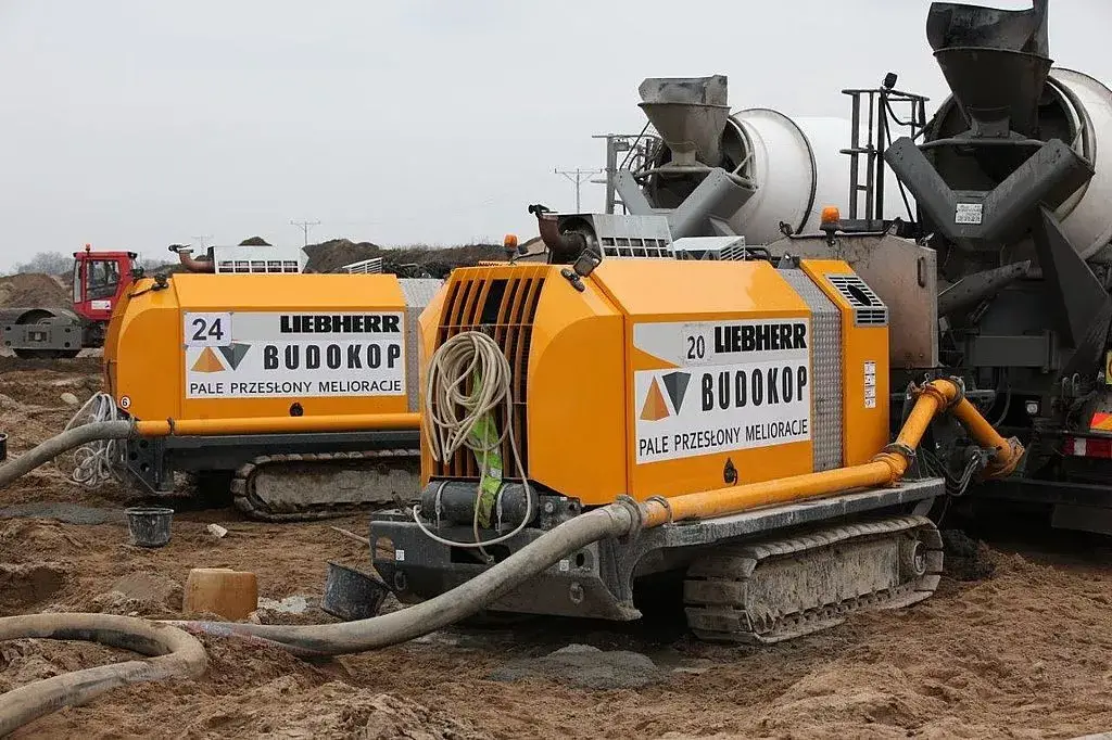
Truck Mounted Concrete Pumps
A Truck Mounted Concrete Pump (TMCP) is a specialized construction equipment that combines a concrete pump with a truck chassis. It’s designed to transport liquid concrete from a mixing plant to a construction site and then pump and place the concrete at the desired location. The integration of a concrete pump with a truck provides mobility, convenience, and versatility, making it an essential tool in modern construction projects.
Truck Mounted Concrete Pumps come in various sizes and configurations to suit different project requirements. They are commonly used for a wide range of construction projects, including residential buildings, commercial structures, bridges, and infrastructure development. Their combination of mobility, efficiency, and precision has made them an indispensable tool in the modern construction industry.
Concrete Pump Manufacturers
There are several renowned manufacturers of concrete pumps that have gained prominence in the construction industry due to their quality, innovation, and reliability. Please note that the status of manufacturers may have evolved since then, but here are some well-known concrete pump manufacturers that were recognized for their products:
- Putzmeister: A German-based company known for its innovative concrete pumps and equipment. Putzmeister has a global presence and offers a wide range of pumping solutions, including both truck-mounted and trailer-mounted pumps.
- Schwing: Another prominent German manufacturer, Schwing, has a strong reputation for its high-quality concrete pumps and equipment. They are known for their advanced technology and durability.
- SANY Group: SANY is a Chinese multinational corporation that has become a major player in the construction equipment industry, including concrete pumps. They offer a variety of concrete pumps designed for different applications.
- Zoomlion: Another significant Chinese manufacturer, Zoomlion, produces a range of construction machinery, including concrete pumps. They are known for their innovation and focus on sustainable solutions.
- CIFA: An Italian manufacturer that produces a wide range of concrete pumps and related equipment. CIFA has a long history in the industry and is recognized for its quality and reliability.
- Liebherr: Liebherr, based in Germany, is a well-established manufacturer that offers a diverse lineup of construction equipment, including concrete pumps. They are known for their engineering excellence and technological advancements.
- Junjin: Junjin is a South Korean manufacturer that produces various concrete equipment, including concrete pumps. They are recognized for their commitment to quality and innovation.
- Everdigm: Everdigm, a South Korean company, specializes in producing construction machinery, including concrete pumps. They are known for their advanced technology and efficiency.
- KCP Heavy Industries: Based in South Korea, KCP manufactures a range of concrete pumps that are used globally. They are known for their reliability and performance.
- Reed Concrete Pumps: Reed is an American manufacturer known for producing high-quality trailer-mounted and truck-mounted concrete pumps. They have a strong reputation in the industry.
Conclusion
Concrete pumps have emerged as a game-changer in the construction industry, streamlining processes, enhancing efficiency, and elevating the overall quality of construction projects. Their ability to deliver concrete with precision, speed, and accessibility has made them an indispensable tool for projects ranging from residential buildings to monumental structures. As technology continues to advance, it’s likely that concrete pumps will evolve further, continuing to shape the way we build and innovate in the world of construction. Whether it’s reaching great heights with a boom pump or navigating tight spaces with a line pump, these machines are a testament to human ingenuity and the pursuit of excellence in construction practices.