
Many of the failures that we experience in the process industry are due to overpressure. Overpressure is the result of unbalance or disruption of normal flows of material and energy. This causes material or energy, or both, to build up in some part of the system. Overheating above the design temperature may also result in overpressure, due to the reduction in allowable stress.
What is the meaning of Pressure in a Pressure Vessel
Let us first understand what pressure is and what is its impact on pressure vessels.
The pressure is force per unit area (Pressure = Force/ Area)
It’s like many small weights sitting on a surface & many small weights add up to a big weight.
So at a given pressure, the LARGER the area, The LARGER the force
Can you imagine 1 barg pressure acting on a 20” manway exerts a 20270 Newton force? This is equivalent to lifting a 2 Tons weight.
Calculation: (100000*PI*(0.508)^2)/(4*9.8) = 20270N
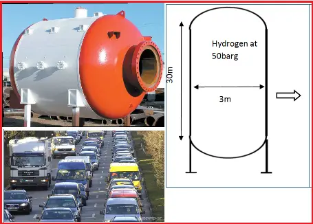
Pressure Vessels (Fig. 1)
We cannot imagine the oil and gas industry without pressure vessels and these include separators, Knock Out drums, columns, steam drums, etc.
The thermodynamic energy contained in a pressure vessel can be very large.
The energy stored in this pressure vessel operating at 50 barg is 0.5*10^10 NM
This is equivalent to the kinetic energy of 13000 cars of 1000 kg each driving at a speed of 100km/hr
Effects of Pressure:
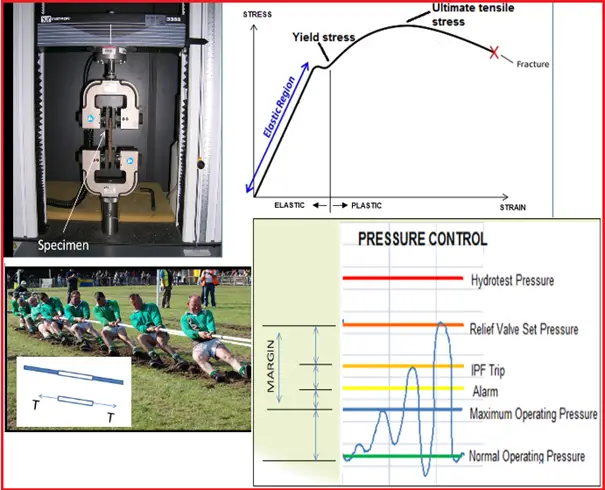
You might have seen or participated in Tug of war or rope pulling where two teams pull on opposite ends of a rope.
In a similar way if we apply tension or stress to a steel specimen by pulling it to different levels the specimen under stress starts to deform and elongate.
The strain is a measurement that gives the change in length of an object divided by the original length
With increasing stress, if we measure corresponding strains, then we can plot a stress-strain curve for that specimen as shown on the right.
Deformation in the elastic region is reversible i.e. Once the forces are no longer applied, the object returns to its original shape.
Plastic deformation is not reversible.
Yield stress is the minimum stress that causes a material to lose its elastic behavior and deforms permanently.
Ultimate Tensile stress is the maximum stress that a material can handle before breaking.
Pressure inside also subjects equipment to stress. If a vessel designed for 3.5 barg pressure is subjected to higher pressures, it may result in catastrophic failure.
Pressure Vessel Codes
Robust Process and Mechanical Design are the fundamental and first barriers to ensuring safe operations.
At the start of the 20th Century, there were numerous incidents related to pressure vessels and manufacturers started to exchange their know-how and experiences. This finally resulted in the nationalized codes on pressurized equipment. Applying a pressure vessel code provides the equipment with sufficient margins against failure under specified temperatures and pressures.
The pressure vessel code allows pressure vessels to be designed, operated, and manufactured along with rules set up by the industry and is widely used by manufacturers and operators.
The main objectives of the pressure vessel codes
- Ensure that the vessel will be safe under all foreseeable circumstances.
- Define minimum protection requirements
- Clearly define the responsibilities of various parties in design and construction
- Give requirements for manufacturing and quality control of equipment
- Clearly define operating windows for safe operations
An important concept of vessel design is to yield stress. if stresses higher than the yield stress (which is temperature-dependent) of a given material are applied then elastic or eventually plastic deformation may occur.
As per Pressure Vessel Code ASME Section VIII Div. 1
Design stress of a pressure vessel = lowest of:
- Ultimate tensile stress / 3.5
- Yield stress / 1.5
- Creep rupture stress / 1.5
Designing for High Pressure
Ideally, all process equipment would be designed to withstand the maximum pressure which can be attained in service during normal operating, upset, start-up, and shutdown conditions. However, in some cases it may not be economically feasible to do this.
Equipment/vessels are usually designed for the pressure which is calculated by adding a margin to maximum operating pressure and full protection is achieved by a relief valve set at or below specified design pressure. The accepted margin is adequate for normal control of the process but not to cope with deviations when control is lost or inadequate. The high-pressure alarm and a high-pressure trip are provided within this margin to avoid unintentional relief valve opening. This keeps the process within the set boundaries “The design envelops.”
For example, centrifugal pumps are often not provided with a relief valve as they are designed for the highest possible pressures corresponding to the blocked outlet condition whereas the associated piping and vessels are protected by a relief valve.
Pressure Terminology
It is important to understand the different terms used in the context of pressure:
Operating pressure (OP): The OP is the gauge pressure that prevails inside equipment and piping during any intended operation. The OP is determined by the process engineer.
Maximum operating pressure (MOP): The MOP is typically
- MOP = OP + 1 (If OP below 20 barg)
- MOP = 105% of OP (If OP above 20 barg)
Design pressure (DP): The DP is the gauge pressure at the top of the equipment in its operating position. It is used to determine the minimum thickness of equipment parts at the Design Temperature.
The DP is initially selected by the process engineer and finally determined in close consultation with the mechanical design engineer.
The following three scenarios are commonly used for determining DP
- For non-liquid full systems with a vapor relief to the atmosphere, DP is normally determined from the MOP by the following rules:
- DP = MOP + 1 (Below 10 barg)
- DP = 110% of MOP (Above 10 barg)
- Vapor relief to flare system: Equipment that is part of a pressure system protected by a relief valve discharging into a flare system or combined vent system shall have a minimum design pressure of at least 3.5 bar (g).
Thus, in this case, DP = Max of : MOP+1; 110% of MOP; at least always 3.5 barg. This is because a minimum of 3.5 barg pressure is required to transfer the relieving pressure to the flare tip (against all the back pressure present).
- For liquid full systems, DP=Maximum shut-off pressure of the pump.
Since the DP is related to the top of the equipment, for other parts or elements of the equipment the designer shall establish the associated design pressures taking into account the maximum pressure drops caused by flow through the equipment, plus the fluid static head.
Maximum allowable working pressure (MAWP):
The MAWP is used in the ASME Boiler and Pressure Vessel Code and a number of other codes referring to it. The MAWP is the maximum gauge pressure permissible at the top of the equipment with the equipment installed in its operating position and at a designated temperature. For the existing equipment, the MAWP is calculated based on the type of material its wall thickness, and its service conditions.
MAWP ≥ DP
Lower Design Pressure
The Lower Design Pressure is the external design pressure or the sub-atmospheric pressure at the top of the equipment in its operating position. It is used to determine the minimum thickness of equipment parts or stiffening rings at the design temperature.
In vacuum systems, the pressure is pushed inward and comes from the atmosphere. Some processes which require vacuum design conditions
- When cooldown is expected,
- Components with a boiling point below 0 °C,
- Steam side of heat exchangers or vessels with steam.
- Pumping out in absence of adequate replacement with vapor
Low-pressure storage tanks and railcars are particularly susceptible to damage. If tanks or vessels are not designed for vacuum, it is likely they will be damaged if placed under vacuum.
With the exception of storage tanks that are protected by pressure-vacuum vents, process vessels that can be subjected to a vacuum shall be rated for that vacuum. Vessels that are in steam service should be designed for full vacuum at 150 °C
Here are a few examples of things going wrong:
A tank was being painted and the painters had covered the vent with plastic sheeting. When operations started to empty the tank, it collapsed before the plastic sucked through.
The tanker was being steam cleaned and, at the end of the job, the hatches were closed. With no vacuum breaker fitted, as the steam condensed, the tanker imploded.
Guidelines for Design Temperature
After pressure, it is important to understand the different terms in the context of temperature
Operating Temperature (OT): The OT is the temperature that prevails inside equipment and piping during the pre-dominant intended operation (in0C).
Maximum Operating Temperature (MOT): If operational flexibility is needed the MOT is established higher than the OT, otherwise they are equal.
- MOT ≥ OT
Sometimes the MOT equals the maximum equilibrium temperature of the composition in the vessel at the Maximum Operating Pressure. Also many times multiple OTs are specified.
Mechanical Design Temperature (MDT) and Upper Design temperature (UDT): The Mechanical Design Temperature (MDT) is often referred to as the upper design temperature (UDT). The UDT is the highest temperature to which equipment may be subjected at the upper and/or lower design pressure. The MDT is typically 10 °C above the MOT
- DT = MOT + 100C
The design pressure and temperature form the basis for mechanical design for equipment and piping and are used in conjunction (coincident design conditions) for calculating minimum wall thickness for vessel and piping design
Lower Design Temperature (LDT): The LDT is the lowest temperature to which equipment may be safely subjected at its design pressure with respect to brittle fracture control. DEP 30.10.02.31-Gen contains details for designing to safeguard against brittle fractures
Brittle Fracture
Brittle Fracture is a condition that occurs when a material is subjected to temperatures that make it less resilient, and therefore more brittle.
The potential for material to become brittle depends on the type of material that is subjected to these low temperatures. Some materials, such as carbon and low alloy steels will become brittle at low temperatures and therefore susceptible to damage ranging from cracking to shattering or disintegration of equipment.
When a material becomes brittle, the consequences can be very serious. If the brittle material is subjected to an impact or an equivalent shock (ex. rapid pressurization) the combination could potentially lead to catastrophic failure under certain conditions.
A serious brittle fracture incident occurred at the ESSO Longford gas plant in Australia in Sept 1998 when a heat exchanger failed catastrophically due to exposure to low temperatures. The released hydrocarbons caused a massive explosion. Two employees were killed, eight others were injured and supplies of natural gas to domestic and industrial users were halted. So, Any possibility of re-pressurization, or pressurization from connected systems, whilst the equipment is colder than the LDT shall be prevented to avoid brittle fracture failures.
Few more Resources for you..
A short Presentation on Basics of Pressure Vessels
Brief Explanation of Major Pressure Vessel Parts
A Presentation on VESSEL CLIPS or VESSEL CLEATS
10 points to keep in mind while using project specific pressure vessel nozzle load tables during stress analysisOnline Course on Pressure Vessels
If you wish to learn more about Pressure Vessels, their design, fabrication, installation, etc in depth, then the following online courses will surely help you:
In case of pressure vessels working under internal vaccum , the hoop stress will be compressive .
What will be the change in radius- negative or positive?
As i can say it will be negative.
But how to say it in a equation form and derive mathematically.
Hello Mr.Dey,
Thanks for this excellent article and those simplified information.
I was kindly inquiring about a technical stuff of two vessels. A column with a design temperature of 250 C, the bottom liquids are directed to a separation drum downstream with a design temperature of 150 C. My question here, is it possible that the column and this drum to be connected directly together WITHOUT any valve in between ? even if the two vessels have this big difference in design temperatures? what’s the code that allows or prevent this ?
Thanks again for your kind support and valuable experience.
Omar
Really Engineer. I don have any word to say you. an excellent explanation . I got many knowledge that I haven’t ever get from other references