What is a Pressure Vessel Clip?
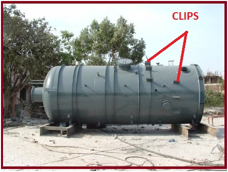
The attachments welded to the equipment by the vendor for bolting the brackets for pipe support are known as Pressure Vessel clips or Cleats. Fig. 1 shows typical clips for a horizontal pressure vessel. Pressure Vessel clips are used mainly for supporting purposes. They are also known as Vessel attachments or Vessel Cleats and form a major pressure vessel attachment part.
Features of Vessel Clips
Equipment requires hydro/ pneumatic testing at the vendors’ workshop to check leakage possibility and after the testing, no welding is permitted on the equipment as it may require stress relieving, radiography, and subsequently re-hydro testing. Also, brackets are not welded directly to the vessel as it is difficult to transport and erect the equipment at the site. So vendors provide clips or cleats in the form of extended attachments from the vessel plate at the required locations specified by the piping team.
Vessel clip information is furnished to the mechanical static equipment department which they forward to the equipment vendor/manufacturer along with nozzle orientation.
The vendor prepares a surface development drawing of the vessel and can check the fouling with weld seam and neighboring nozzles or clips.
Vessel Clip Selection Procedure
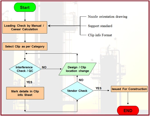
Refer to Fig. 2 for a flow diagram of the Pressure Vessel Clip selection procedure.
Major Considerations for Clip Loading
The Vessel clip should be able to take the worst load combination possible as per stress analysis criteria.
- Operating load: pipe metal weight +pipe component weight like a valve, flanges etc.+ Insulation + fluid + thermal load (at operating/ design conditions).
- Hydrotesting load: clip load during the hydro test ( Without insulation)
- Occasional loads: pipe metal weight + pipe component weight like a valve, flange etc.+ Insulation wt.+ Fluid weight+ thermal load at operating (not at design conditions)+ wind/ seismic load.
Few Salient Points
The following points are to be kept in mind while providing clip-loading information.
If a vapor line is to be hydro-tested and its load is exceeding the vessel cleat/clip allowable: In that case, the line can be hydro-tested (along with the column) at the ground and can be erected with the column.
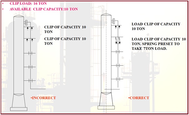
If the operating load is more than the equipment cleat capacity: A second load-taking support (usually spring support) is used as shown in Fig. 3 below.
How to Choose the Location of the Vessel Cleat
Follow the below-mentioned steps while selecting the vessel clip location.
- The first clip should be load-taking support
- As close as possible to the nozzle.
- To reduce the differential thermal expansion between the pipe and the column/ vessel.
- After that guide clip should be provided after the specified span and then based on a guide span for vertical lines guides to be provided.
- There may be high sustained stress at the bend with only one load-taking clip support.
- The requirement for the second load-taking clip should be checked.
- The second load-taking clip may require spring support.
Points to Check while Deciding Vessel Clips
While deciding on clip location and load, always check the following points
- Load Capacity
- Pipe Insulation: bare or insulated pipe
- Width of bracket: based on insulation the width of the bracket
- Bracket length limitations
- Fouling: bracket should not foul with the adjacent bracket, adjacent pipe, weld joint of elbow, the pad of nozzle
How to Avoid Fouling with Vessel Clip
- By staggering the supports
- By changing the orientation of the line
- Choosing the suitable bracket
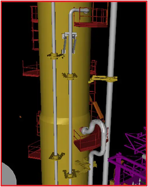
Fig. 4 shows a typical pipe supported by vessel clips.
Usual Equipment having Cleat or Clip Supports
Supporting pipes using clips or cleats is more common for towers or columns. However, sometimes the cleat support is taken from the following equipment to support pipes.
Few more Resources for you..
A short Presentation on Basics of Pressure Vessels
Brief Explanation of Major Pressure Vessel Parts
10 points to keep in mind while using project specific pressure vessel nozzle load tables during stress analysis
Understanding Pressure and Temperature in the context of Pressure Vessel Design
A Video tutorial on “Comprehensive Design Code Coverage for Pressure Vessel and Heat Exchanger Design” by Bentley InstituteOnline Course on Pressure Vessels
If you wish to learn more about Pressure Vessels, their design, fabrication, installation, etc in depth, then the following online courses will surely help you:


A very interesting article.
However, can you please share any C2 model where more than one load taking clip have been used ? My e-mail id is ani_dat@yahoo.co.in
This article is really helpful for me…
Dear sir, I m also an Mechanical Engineer and started working in Pressure vessel design from last 6 months and I want to increased my technical knowledge in this field so what should I do for that ? Can you please suggest?
who will design the cleat?
vendor?
mechanical static?
structural?
piping?
Hi Anup,
There is one requirement of Glue cleat on the Sphere as welding is not permitted. Can you give me some reference for design of the same.
Sir Draughtsman mechanical fresher vacancy available is.. pune
Nice & helpful article.