
Pressure Vessels are one of the most important Static or stationary equipment for any process plant. We can not think about any chemical plants or Refineries or Petrochemical complex which runs Without any Pressure Vessel. Major chemical processes happen inside pressure vessels. These may be vertical or horizontal and are known by various names like column, drum, reactor, exchanger, etc. They can carry or process fluids of various temperatures and pressure ranges. Most of the time these are designed following the ASME BPVC code. In this article, major component vessel parts will be explained in brief.
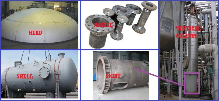
Head (Fig. 1): The end enclosures of a vessel. They can be semi-elliptical, spherical, or dished.
Shell (Fig. 1): The cylindrical walls of a vessel. Sometimes shells can be insulated depending on body temperature or process conditions
Pressure Vessel Nozzle (Fig. 1): The tie-in connection between the vessel or equipment and the piping system. Nozzles are provided in locations where a commodity is either introduced or removed from a vessel or piece of equipment.
Nozzle orientation: The angular arrangement of nozzles around the perimeter of a vessel’s shell.
Nozzle projection: Used to establish the distance from the vessel’s centerline to the nozzle’s face of the flange.
Base plate: A flat, metal ring welded to the bottom of a vessel’s supporting skirt that rests on a concrete foundation. Holes around the perimeter of the metal ring make it possible to position it over anchor bolts and secure it to the foundation.
Skirt (Fig. 1): A cylinder-shaped support for a vertical vessel. One end is welded to the base plate allowing it to rest on the foundation and the other end is welded to the bottom head of a vertical vessel.
Skirt access opening: An 18’’ ID hole 2’-6’’ above the foundation that allows workers entrance for inspection and maintenance.
Skirt vents: Equally spaced holes approximately 3 to 4 in diameter bored near the top of the vessel skirt that allows toxic and explosive gases to escape.
Skirt fireproofing: Generally brick or granite, fireproofing is applied around the interior and exterior walls of a vessel skirt. It is necessary to prevent damage to the vessel skirt in case a fire occurs.
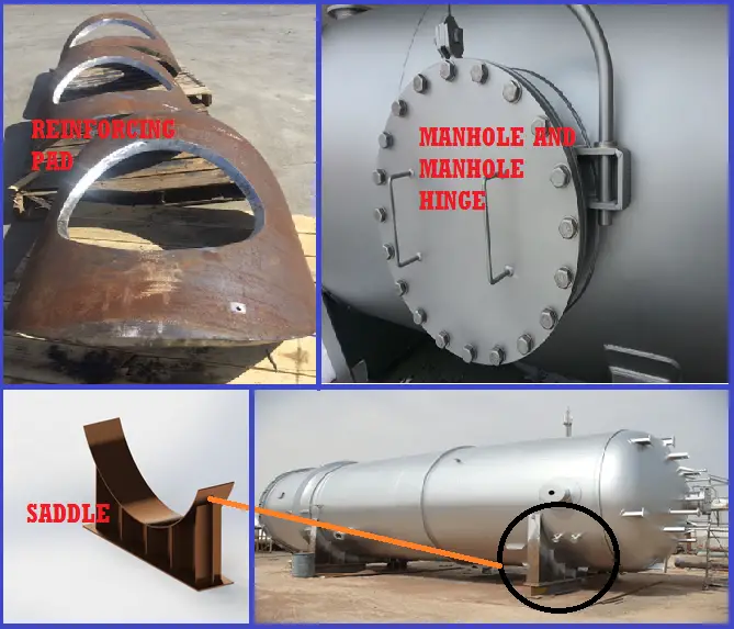
Reinforcing pad (Fig. 2): A plate contoured to the shape of a vessel shell. It is positioned around nozzles and provides additional strength in the areas where metal was removed from the shell.
Manholes (Fig. 2): Similar to large nozzles that allow workers entry points into a vessel. They generally are 18 IDs and are accessible by ladders and platforms. When not in use, the manhole is sealed with a blind flange.
Manhole hinge (Fig. 2): A hinge that creates a pivot point allowing the blind flange attached to the manhole to be easily removed for worker entrance.
Seal pan: A tray installed below the bottom tray in a vessel to prevent liquids from bypassing the trays.
Trays: Flat metal plates spaced approximately 18 to 24 apart inside a vertical vessel. They can be bolted or welded to the vessel shell. Trays are perforated to allow rising vapors and falling liquids to pass through with the aid of a valving mechanism called a cap.
Weir: A dam-like plate welded on a tray that allows a fractionated by-product to collect and be extracted by a nozzle.
Downcomers: Openings adjacent to a tray that allows liquids flowing over a weir plate to fall to the tray below and begin the fractionation process over again.
Insulation rings: Continuous circular rings welded to the exterior of a vertical vessel that supports a vessel’s insulation. They are typically spaced on 12–0 centers.
Saddles (Fig. 2): U-shaped supports welded on horizontal vessels and exchangers. Saddles are bolted to concrete foundations and create cradle-like support in which the vessel can rest.
Lifting lugs: donut-shaped rings welded to the vessel’s shell or head that allow the vessel to be raised and positioned during installation.
Few more Resources for you..
A short Presentation on Basics of Pressure Vessels
A Presentation on VESSEL CLIPS or VESSEL CLEATS
10 points to keep in mind while using project specific pressure vessel nozzle load tables during stress analysis
Understanding Pressure and Temperature in the context of Pressure Vessel Design
A Video tutorial on “Comprehensive Design Code Coverage for Pressure Vessel and Heat Exchanger Design” by Bentley Institute
This article is prepared by Mr. Satish Atmanathan, a senior oil and gas professional with extensive work experience. For a more detailed explanation of all the above parts and visualization, listen directly to him in the following video:
Online Course on Pressure Vessels
If you wish to learn more about Pressure Vessels, their design, fabrication, installation, etc in depth, then the following online courses will surely help you:
according to standard what is the procedure to open inspection door in high pressure vessel head ,thk=40 mm , material carbon steel
Do we need a nozzle at top of vertical Air Receivers which is not connected to any requirement? Is it mandatory to provide a vent or like ?
as of now no query, may be in future i will connect