Piping systems are an integral part of industrial processes. The efficient and safe operation of piping systems depends on a number of factors, one of which is the design and installation of piping vibration isolators. Piping vibration isolators are used to control and reduce the transmission of vibration and noise through piping systems. This article will discuss the importance of piping vibration isolators, their design and installation, and the factors to consider when selecting the appropriate isolators for a particular piping system.
Importance of Piping Vibration Isolators
Piping vibration can cause a number of problems in industrial processes, such as increased wear and tear on equipment, increased maintenance costs, decreased efficiency, and safety hazards. Vibration can be caused by a number of factors, including fluid flow, pressure changes, mechanical equipment, and external sources such as wind and earthquakes. Piping vibration isolators are designed to control and reduce the transmission of these vibrations, protecting the piping system and other equipment from damage and ensuring efficient and safe operation.
Design and Installation of Piping Vibration Isolators
Piping vibration isolators are typically made of elastomeric materials, such as rubber or neoprene, and are designed to provide a flexible connection between the piping system and the supporting structure. The isolators are installed at the points where the piping system is attached to the supporting structure, such as pipe hangers, supports, and anchors. The design and installation of the isolators should be based on the specific requirements of the piping system, taking into consideration factors such as the size and weight of the piping, the type of fluid being transported, the operating temperature and pressure, and the frequency and amplitude of the vibrations.
Types of Vibration Isolators
There are several types of vibration isolators that can be used for piping systems, including:
Spring Isolators: Spring isolators use metal springs to absorb and dampen vibrations. They are typically used in applications where the frequency of vibration is high.
Rubber Isolators: Rubber isolators use elastomeric materials, such as neoprene or natural rubber, to dampen vibrations. They are typically used in applications where the frequency of vibration is low to medium.
Inertia Base Isolators: Inertia base isolators use a heavy mass, such as a concrete block, to provide a stable base for the piping system. They are typically used in applications where the frequency of vibration is low.
Friction Pad Isolators: Friction pad isolators use a pad of material, such as cork or felt, to dampen vibrations. They are typically used in applications where the frequency of vibration is low to medium.
Air Spring Isolators: Air spring isolators use a chamber of air to absorb and dampen vibrations. They are typically used in applications where the frequency of vibration is low to medium.
Wire Rope Isolators: Wire rope isolators use multiple strands of wire rope to provide a flexible connection between the piping system and the supporting structure. They are typically used in applications where the frequency of vibration is high.
The type of vibration isolator used will depend on the specific requirements of the piping system, taking into consideration factors such as the size and weight of the piping, the type of fluid being transported, the operating temperature and pressure, and the frequency and amplitude of the vibrations.
Factors to Consider When Selecting Piping Vibration Isolators
When selecting piping vibration isolators, there are a number of factors to consider. These include:
Material: The material of the isolator should be selected based on the specific requirements of the piping system, taking into consideration factors such as the type of fluid being transported, the operating temperature and pressure, and the frequency and amplitude of the vibrations.
Load capacity: The isolator should be able to support the weight of the piping system and the fluid being transported.
Frequency and amplitude of vibrations: The isolator should be designed to provide sufficient damping of the vibration frequency and amplitude.
Operating temperature and pressure: The isolator should be able to withstand the temperature and pressure of the fluid being transported.
Environmental conditions: The isolator should be able to withstand the environmental conditions of the installation site, such as wind, rain, and temperature fluctuations.
Installation requirements: The isolator should be designed to meet the specific installation requirements of the piping system, such as the type of pipe hanger or support being used.
Components of Piping Vibration Isolators
Piping vibration isolators consist of several components that work together to reduce and control the transmission of vibration and noise through piping systems. The components of piping vibration isolators typically include:
Base Plate: The base plate is the component that attaches the isolator to the supporting structure, such as a pipe hanger or support.
Load Plate: The load plate is the component that attaches the isolator to the piping system.
Isolation Element: The isolation element is the component that provides the flexibility and damping required to reduce the transmission of vibration and noise. The isolation element can be made of different materials, such as rubber, neoprene, or metal springs, depending on the specific requirements of the piping system.
Bolts and Nuts: Bolts and nuts are used to secure the base plate, load plate, and isolation element together.
Washer: Washers are used to distribute the load evenly across the isolation element and to prevent damage to the isolation element.
Lateral Restraint: Lateral restraints are used to prevent the piping system from moving laterally, which can cause damage to the isolation element.
The design and selection of these components will depend on the specific requirements of the piping system, such as the size and weight of the piping, the type of fluid being transported, the operating temperature and pressure, and the frequency and amplitude of the vibrations. Proper selection and installation of these components are essential to ensure that the piping vibration isolators perform effectively and reliably.
Conclusion
Piping vibration isolators are an important component of industrial piping systems, protecting equipment from damage and ensuring efficient and safe operation. The design and installation of piping vibration isolators should be based on the specific requirements of the piping system, taking into consideration factors such as the size and weight of the piping, the type of fluid being transported, the operating temperature and pressure, and the frequency and amplitude of the vibrations. When selecting piping vibration isolators, it is important to consider factors such as material, load capacity, frequency and amplitude of vibrations, operating temperature and pressure, environmental conditions, and installation requirements. By selecting the appropriate piping vibration isolators, industrial processes can operate efficiently and safely, with reduced maintenance costs and increased productivity.
Pipeline cleaning refers to the process of removing contaminants and debris from the inside of pipelines that are used to transport fluids such as water, oil, and gas. Over time, pipelines can accumulate sediment, scale, rust, and other materials that can reduce their efficiency and lifespan.
Pipeline cleaning typically involves the use of specialized equipment and techniques, such as high-pressure water jetting or chemical cleaning agents, to dislodge and remove these materials. The cleaning process is often conducted in stages, with an initial inspection to determine the extent of the buildup, followed by the selection of appropriate cleaning methods and equipment, and finally, a post-cleaning inspection to ensure that the pipeline is free of debris and functioning properly.
Regular pipeline cleaning is an important maintenance activity for ensuring the safe and efficient operation of pipelines and reducing the risk of pipeline failure or environmental damage.
How to Clean Pipelines?
Cleaning pipelines typically involves several steps and may vary depending on the type of pipeline and the materials that need to be removed. Here are some general steps that may be involved in cleaning pipelines:
Inspection: The first step is to inspect the pipeline to determine the extent of buildup or damage. This can be done using various inspection techniques such as video cameras, ultrasonic testing, or magnetic flux leakage.
Select cleaning method: Depending on the type and extent of buildup, the appropriate cleaning method can be selected. Some common cleaning methods include:
Mechanical cleaning: This involves the use of mechanical devices such as scrapers or pigs to remove debris from the pipeline walls.
Chemical cleaning: Chemicals are used to dissolve or loosen buildup and contaminants, which can then be flushed out of the pipeline using water or air.
High-pressure water jetting: This involves the use of high-pressure water to dislodge and remove debris from the pipeline walls.
Cleaning process: Once the cleaning method is selected, the cleaning process can begin. The pipeline is typically isolated and the cleaning equipment is inserted into the pipeline. The cleaning process may involve multiple passes with the equipment, and may also involve the use of chemicals or other cleaning agents.
Inspection: After the cleaning process is complete, the pipeline is inspected again to ensure that all debris has been removed and the pipeline is functioning properly.
Overall, pipeline cleaning is a complex and specialized process that requires careful planning, specialized equipment, and experienced operators. It is important to follow appropriate safety procedures and to work with trained professionals to ensure the safe and effective cleaning of pipelines.
What are the Methods of Industrial Pipeline Cleaning?
There are several methods that can be used for industrial pipeline cleaning, and the selection of the appropriate method depends on the type and extent of buildup or contaminants in the pipeline. Some common methods of industrial pipeline cleaning include:
Mechanical cleaning: This method involves the use of mechanical devices such as pigs, scrapers, or brushes to physically remove buildup and debris from the pipeline walls. Mechanical cleaning is often used in pipelines with heavy deposits or hard-to-remove materials.
Chemical cleaning: Chemical cleaning involves the use of cleaning agents, such as acids or solvents, to dissolve or loosen buildup and contaminants, which can then be flushed out of the pipeline using water or air. This method is often used for pipelines with organic or inorganic deposits, such as scale or rust.
High-pressure water jetting: This method uses high-pressure water to dislodge and remove debris from the pipeline walls. Water jetting is effective for removing soft deposits, such as sludge or mud, and can be used for cleaning pipes of various sizes and materials.
Ultra-high-pressure water jetting: This method uses even higher-pressure water (typically above 20,000 psi) to remove very hard and stubborn deposits, such as concrete or hardened scale. This method requires specialized equipment and trained operators.
Vacuum cleaning: This method uses a vacuum truck or other suction device to remove debris and contaminants from the pipeline. Vacuum cleaning is often used for pipelines with loose or granular materials, such as sand or gravel.
Foam cleaning: This method involves the use of a cleaning foam that is injected into the pipeline to loosen and remove buildup and contaminants. The foam is then flushed out of the pipeline using water or air.
Overall, the selection of the appropriate pipeline cleaning method depends on several factors, including the type and extent of buildup or contaminants, the size and material of the pipeline, and the desired cleaning outcome. It is important to work with trained professionals to ensure the safe and effective cleaning of industrial pipelines.
How to Choose a Pipeline Cleaning Method?
Choosing the right pipeline cleaning method is important for effective and efficient cleaning, and the selection of the appropriate method depends on several factors. Here are some considerations when choosing a pipeline cleaning method:
Type of buildup: The type of buildup or contaminants in the pipeline will determine the most effective cleaning method. For example, mechanical cleaning may be appropriate for hard deposits like scale, while chemical cleaning may be best for organic materials like oil or grease.
Pipeline size and material: The size and material of the pipeline will also influence the choice of cleaning method. For example, high-pressure water jetting may be suitable for small-diameter pipes made of soft materials like plastic or rubber, while ultra-high-pressure water jetting may be required for larger-diameter pipes made of hard materials like steel.
Environmental considerations: Considerations such as water availability, wastewater treatment, and potential environmental impact should also be taken into account when choosing a pipeline cleaning method.
Safety considerations: Pipeline cleaning can be a hazardous process, and safety should always be a top priority. Considerations such as operator training, personal protective equipment, and safe handling of chemicals or high-pressure equipment should be taken into account when choosing a pipeline cleaning method.
Cost and time considerations: The cost and time required for pipeline cleaning should also be considered when choosing a cleaning method. For example, some methods may require more equipment or specialized operators, which can increase the cost of cleaning.
Overall, the selection of the appropriate pipeline cleaning method requires careful consideration of several factors. It is important to work with experienced professionals who can help determine the best method for your specific pipeline cleaning needs.
Is Pigging the most efficient method for Pipeline Cleaning?
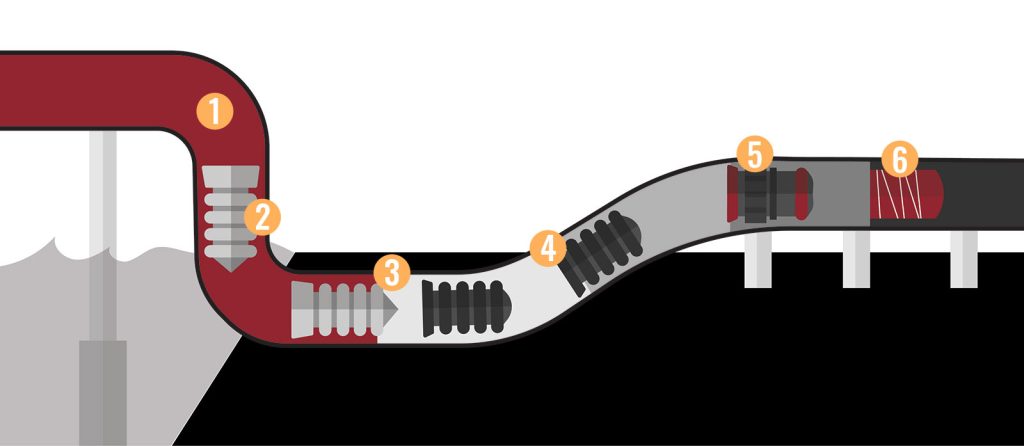
Pigging can be a highly efficient method for pipeline cleaning, especially for pipelines with heavy deposits or hard-to-remove materials. The use of pigs, which are cylindrical or spherical devices that are inserted into the pipeline and propelled by fluid flow, can help remove debris and buildup from the pipeline walls.
One advantage of pigging is that it can be used for both cleaning and inspection, as some pigs are equipped with cameras or sensors that can detect pipeline defects or damage. Pigging is also a relatively fast method of cleaning, as it can be performed while the pipeline is still in operation.
However, pigging may not be suitable for all pipeline cleaning needs. For example, pigging may not be effective for removing soft deposits like sludge or mud, and may not be appropriate for pipelines with complex geometry or multiple bends. Additionally, pigging requires specialized equipment and trained operators, which can increase the cost of cleaning.
Overall, while pigging can be an efficient method for pipeline cleaning in certain situations, the selection of the appropriate cleaning method depends on several factors, including the type and extent of buildup, the size and material of the pipeline, and the desired cleaning outcome. It is important to work with experienced professionals to determine the best method for your specific pipeline cleaning needs. Fig. 1 (Image Credit: https://internalpipeline.com/pipeline-cleaning/ )below shows a typical schematic of pipeline cleaning using PIGs.
Fig. 1: Cleaning Pipeline Using PIGs
What is swabbing in pipeline cleaning?
Swabbing is a pipeline cleaning method that involves using a soft, flexible cylinder (known as a “swab”) to remove debris, liquids, or other contaminants from the inside of a pipeline. The swab is typically made of foam, rubber, or other materials that are compatible with the pipeline contents.
The swabbing process involves inserting the swab into the pipeline and then using pressure to propel it through the pipeline, either by pumping it or by using the pipeline’s own fluid flow. As the swab moves through the pipeline, it picks up and removes debris and liquids from the walls of the pipeline.
Swabbing is often used in pipelines where other cleaning methods, such as pigging or flushing, are not effective or practical. It is also used as a pre-cleaning method prior to pigging or flushing to remove large debris or obstructions that could damage the pig or block the flushing process.
Swabbing can be used in pipelines that transport a variety of materials, including oil, gas, water, and chemicals. It is a relatively low-cost and simple method of pipeline cleaning that can be performed quickly with minimal disruption to the pipeline’s operations. However, it may not be as effective as other cleaning methods for removing stubborn deposits or for cleaning long or complex pipelines.
What is Ice Pigging?
Ice pigging is a pipeline cleaning method that uses a slush of ice and water to remove debris and contaminants from the inside of a pipeline. The ice slurry is pumped into the pipeline and propelled through it by the flow of water. As the slurry moves through the pipeline, it scrubs the walls and removes debris, leaving the pipeline clean.
Ice pigging is particularly effective for removing soft or sticky deposits, such as biofilms, fats, and oils, which can be difficult to remove with other cleaning methods. It can also be used to remove hard deposits, such as scale and mineral build-up, although multiple passes may be required to fully clean the pipeline.
The ice slurry used in ice pigging is typically made by freezing water and then crushing the ice into small pieces. The ice is mixed with water to create a slushy mixture that is pumped into the pipeline. The ice melts as it moves through the pipeline, leaving behind a small amount of water that can be easily removed.
Ice pigging is a relatively new and innovative pipeline cleaning technique that has several advantages over traditional cleaning methods, such as pigging and flushing. It is a low-risk, non-intrusive method that does not require the use of chemicals or abrasive materials. It is also a highly efficient method that can clean pipelines more thoroughly and in less time than other methods.
Ice pigging has been successfully used in a variety of industries, including water treatment, oil and gas, and food and beverage production. It is especially useful for cleaning pipelines in sensitive environments where the use of chemicals or abrasive materials is not allowed.
What is Pipeline Cleaning Service?
Pipeline cleaning services refer to a range of specialized services that are focused on cleaning and maintaining pipelines used in various industries such as oil and gas, petrochemicals, food and beverage, water and wastewater, and others.
Pipeline cleaning services involve the use of various techniques, equipment, and cleaning agents to remove debris, buildup, and other contaminants from the pipeline walls and internal surfaces. The main goal of pipeline cleaning services is to ensure that pipelines remain free of obstruction and buildup, which can cause reduced flow rates, decreased efficiency, and other operational issues.
Pipeline Cleaning Service Companies
There are several reputed companies that offer pipeline cleaning services, including:
Baker Hughes – a leading provider of oilfield services, Baker Hughes offers pipeline cleaning services for the oil and gas industry, using a range of methods including chemical cleaning, high-pressure water jetting, and pigging.
SUEZ – a global environmental services company, SUEZ provides pipeline cleaning services for the water and wastewater industry, using methods such as high-pressure water jetting and vacuum cleaning.
Clean Harbors – a provider of environmental, energy, and industrial services, Clean Harbors offers pipeline cleaning services for various industries, including oil and gas, petrochemicals, and pharmaceuticals.
MPW Industrial Services – a provider of industrial cleaning and maintenance services, MPW offers pipeline cleaning services using a range of methods such as chemical cleaning, high-pressure water jetting, and pigging.
Envirosystems – a provider of environmental and industrial services, Envirosystems offers pipeline cleaning services using methods such as chemical cleaning, high-pressure water jetting, and vacuum cleaning.
HydroChemPSC – a provider of industrial cleaning and environmental services, HydroChemPSC offers pipeline cleaning services using a range of methods such as chemical cleaning, high-pressure water jetting, and pigging.
These are just a few examples of companies that offer pipeline cleaning services. It is important to research and evaluate potential service providers to ensure that they have the experience, expertise, and equipment necessary to meet your specific pipeline cleaning needs.
The National Fire Protection Association (NFPA) has developed a set of standards for fire protection, life safety, and building codes. One of these standards is NFPA 37: Standard for the Installation and Use of Stationary Combustion Engines and Gas Turbines. This standard provides guidelines for the installation, operation, and maintenance of stationary combustion engines and gas turbines to prevent fires, explosions, and other hazards.
Stationary combustion engines and gas turbines are widely used in industrial and commercial settings to provide reliable and efficient power generation. However, the operation and maintenance of these machines come with inherent risks, such as fires, explosions, and toxic gas releases. To mitigate these hazards, the National Fire Protection Association (NFPA) developed a standard, NFPA 37, for the installation and use of stationary combustion engines and gas turbines. This article will provide an overview of NFPA 37, its scope, requirements, and how it helps ensure the safe and reliable operation of stationary combustion engines and gas turbines.
Scope of NFPA 37
NFPA 37 covers the installation, operation, and maintenance of stationary combustion engines and gas turbines that are fueled by natural gas, diesel, or other liquid or gaseous fuels. The standard applies to both new installations and existing ones that undergo modifications or repairs. It also covers both indoor and outdoor installations and equipment that are connected to a building’s electrical and mechanical systems. The current edition of NFPA 37 is NFPA 37-2021.
Requirements of NFPA 37
NFPA 37 sets forth specific requirements to ensure the safe operation of stationary combustion engines and gas turbines. Some of the key requirements include:
Design and Installation: NFPA 37 requires that stationary combustion engines and gas turbines be designed and installed in accordance with recognized engineering standards and codes. This includes compliance with applicable codes such as the National Electric Code (NEC) and the International Building Code (IBC). The standard also provides specific guidelines for the installation of fuel storage and handling systems.
For example, fuel storage tanks must be located outside of buildings or installed in fire-rated enclosures. Piping and tubing used for fuel delivery must be properly grounded, supported, and protected from physical damage.
Location and Clearance: Stationary combustion engines and gas turbines must be located in an area that provides adequate clearance from combustible materials and sources of ignition. The standard specifies minimum clearance distances based on the engine’s power output and fuel type.
Fuel Storage and Handling: The standard provides guidelines for the storage and handling of fuels used in stationary combustion engines and gas turbines. It covers the design, construction, and operation of fuel storage tanks, piping, and associated equipment.
Ventilation: Adequate ventilation is essential for the safe operation of stationary combustion engines and gas turbines. The standard specifies requirements for the design, installation, and operation of ventilation systems that can effectively remove exhaust gases and prevent the buildup of explosive or toxic concentrations.
Electrical Systems: Stationary combustion engines and gas turbines must be equipped with electrical systems that meet the requirements of the National Electric Code (NEC) and other applicable standards. The standard covers the installation, grounding, and bonding of electrical equipment used in these machines.
For example, electrical equipment must be installed in accordance with the NEC and must be properly grounded. Electrical panels and disconnect switches must be located outside of the engine room or turbine enclosure.
Fire Protection: NFPA 37 requires the installation of fire protection systems that can detect and suppress fires that may occur in stationary combustion engines and gas turbines. The standard specifies requirements for fire detection systems, fire suppression systems, and portable fire extinguishers.
For example, fire extinguishers must be located near the engine or turbine and must be easily accessible. Automatic sprinkler systems must be installed in accordance with NFPA 13: Standard for the Installation of Sprinkler Systems.
Maintenance and Testing: To ensure the safe and reliable operation of stationary combustion engines and gas turbines, the standard requires regular maintenance and testing of these machines. It covers the inspection, cleaning, and repair of engine components, as well as the testing and calibration of safety devices and systems.
Training and Documentation: Finally, NFPA 37 requires that personnel who operate or maintain stationary combustion engines and gas turbines be properly trained in their safe operation and maintenance. The standard also requires that documentation be maintained to verify compliance with the standard and to track maintenance and testing activities.
Benefits of NFPA 37
Compliance with NFPA 37 provides several benefits to building owners, operators, and occupants. Some of these benefits include:
Increased Safety: The primary benefit of NFPA 37 is the increased safety of stationary combustion engines and gas turbines. The standard sets forth specific requirements that help prevent fires, explosions, and toxic gas releases, which can cause significant property damage and loss of life.
Compliance with Regulations: Compliance with NFPA 37 ensures that building owners and operators meet the regulatory requirements for the installation and use of stationary combustion engines and gas turbines. Many jurisdictions require compliance with NFPA 37 as a condition for obtaining permits and approvals for these installations.
Protection of Assets: Stationary combustion engines and gas turbines are significant investments for building owners and operators. Compliance with NFPA 37 helps protect these assets by reducing the risk of equipment damage and downtime due to fires, explosions, or other hazardous events.
Improved Efficiency: Compliance with NFPA 37 helps improve the efficiency of stationary combustion engines and gas turbines.
Difference Between NFPA 37 and NFPA 110
NFPA 37 and NFPA 110 are two distinct standards developed by the National Fire Protection Association (NFPA) for different purposes. While both standards relate to emergency power supply systems, they apply to different types of equipment and have different requirements. Here are the key differences between NFPA 37 and NFPA 110:
Scope: NFPA 37 applies to the installation and use of stationary combustion engines and gas turbines, while NFPA 110 applies to emergency and standby power supply systems that provide backup power to buildings and facilities during power outages.
Equipment Types: NFPA 37 applies specifically to stationary combustion engines and gas turbines used for power generation, while NFPA 110 applies to a range of equipment used in emergency power supply systems, including generators, batteries, inverters, and transfer switches.
Fuel Type: NFPA 37 covers stationary combustion engines and gas turbines that are fueled by natural gas, diesel, or other liquid or gaseous fuels, while NFPA 110 applies to emergency and standby power supply systems that can use a range of fuels, including diesel, natural gas, propane, and gasoline.
Installation and Maintenance: NFPA 37 focuses on the installation and maintenance of stationary combustion engines and gas turbines, while NFPA 110 covers the design, installation, testing, operation, and maintenance of emergency and standby power supply systems.
Testing Requirements: NFPA 37 requires regular testing and maintenance of stationary combustion engines and gas turbines, while NFPA 110 sets forth specific testing requirements for emergency power supply systems, such as load testing, transfer switch testing, and fuel system testing.
In summary, while both NFPA 37 and NFPA 110 relate to emergency power supply systems, they cover different types of equipment and have different requirements. NFPA 37 focuses on stationary combustion engines and gas turbines, while NFPA 110 applies to a range of equipment used in emergency and standby power supply systems.
Rust is the bane of metal objects, and it’s especially problematic when it comes to pipes. Rusting pipes can cause water damage, decrease water pressure, and even lead to health problems. In this article, we will discuss the causes of rusting pipes, ways to avoid rust in pipes, how to fix rusty pipes, how to remove rust from pipes, and whether rust in water pipes is harmful.
What is a Rusting Pipe?
Rusting pipes are simply metal pipes that have started to corrode due to exposure to water and oxygen. The corrosion process leads to the formation of iron oxide, also known as rust, which can accumulate inside the pipes, causing blockages and other problems. Rust can also cause the pipes to weaken and eventually leak, leading to significant water damage in your home or business.
Why Do Pipes Rust?
Pipes rust due to a chemical reaction between the metal in the pipes and the oxygen in the water. This process is called oxidation. It is more likely to occur in older pipes that have been in use for a long time. Pipes made of iron or steel are more prone to rusting than other materials such as copper or plastic. Other factors that can contribute to rusting pipes include hard water, pH levels, and the presence of certain minerals in the water.
Pipes rust for a variety of reasons, including the quality of the water, the age of the pipes, and the presence of chemicals in the water. The following are some of the most common causes of rusting pipes:
Water Quality: If the water in your area is hard or has a high mineral content, it can cause rusting in pipes. Hard water contains high levels of dissolved minerals, such as calcium and magnesium, which can build up inside the pipes and cause corrosion.
Age of Pipes: Over time, all metal pipes will rust and corrode. If your pipes are old, they may be more susceptible to rusting and breaking down.
Chemicals in Water: Chemicals such as chlorine, which is commonly added to municipal water supplies, can react with the metal in pipes and cause rusting.
Pipe Material: Some types of metal pipes, such as galvanized steel, are more prone to rusting than others.
Ways to Avoid Rust in Pipes
There are several ways to prevent pipes from rusting and corroding:
Replace Old Pipes: If your pipes are old and rusting, it’s time to replace them. Copper and plastic pipes are less prone to rusting than metal pipes and are a good replacement option.
Water Softener: Installing a water softener can help reduce the mineral content of the water, which can reduce the risk of rusting in pipes.
Pipe Coating: Applying a pipe coating can help protect the metal from the corrosive effects of water and oxygen. Epoxy coatings are particularly effective in preventing rust.
Regular Maintenance: Regular maintenance can help prevent rusting in pipes. Flushing the pipes with water regularly can remove mineral buildup and prevent corrosion.
Use plastic pipes: Plastic pipes are less likely to rust than metal pipes. They are also more durable and easier to install.
Check the pH levels: High pH levels can cause rusting pipes. Regularly checking the pH levels in the water can help prevent rusting.
How to Fix Rusty Pipes?
If your pipes have already started to rust, it’s important to fix the problem as soon as possible to prevent further damage. Here are some steps to take to fix rusty pipes:
Assess the Damage: Before you start any repairs, you need to assess the damage. If the damage is extensive, it may be best to replace the affected pipes.
Shut Off Water: Shut off the water supply to the affected pipes to prevent further damage.
Remove Rust: Use a wire brush or sandpaper to remove any visible rust from the affected pipes.
Apply Coating: Apply a pipe coating to protect the pipes from further rusting.
Apply a rust inhibitor: Applying a rust inhibitor can help prevent rust from forming in the future.
Patch the pipes: Patching the pipes can help fix any leaks or holes in the pipes.
Reconnect Pipes: Reconnect the pipes and turn the water supply back on.
How to Remove Rust from Pipes
Removing rust from pipes is important to prevent further corrosion and damage to the plumbing system. If you want to remove rust from pipes, there are several methods you can use:
Vinegar and Baking Soda: Mix equal parts of vinegar and baking soda and apply the mixture to the affected area. Let it sit for several hours, then rinse it with water.
Lemon Juice and Salt: Mix lemon juice and salt and apply.
Commercial Rust Removers: You can purchase commercial rust removers from your local hardware store. Follow the instructions on the package carefully, and make sure to wear protective gear.
Wire Brush or Sandpaper: Use a wire brush or sandpaper to remove any visible rust from the affected pipes. This method may not be as effective as other methods, but it can help remove surface rust.
Pressure Washing: A pressure washer can help remove rust from pipes, but it should be used with caution. High pressure can damage pipes, so use the lowest pressure possible and keep the nozzle at least 6 inches away from the pipe.
It’s important to note that some of these methods can be harmful to pipes and may even cause more damage. If you’re unsure about how to remove rust from pipes, it’s best to consult with a professional plumber.
Is Rust in Water Pipes Harmful?
Rust in water pipes can be harmful, especially if it’s ingested. Rust can contain harmful bacteria and metals, such as lead, which can cause health problems. Some of the health problems associated with rust in water pipes include:
Digestive Issues: Ingesting rust can cause digestive issues, such as nausea, vomiting, and diarrhea.
Skin Irritation: Rust can cause skin irritation and rashes, especially if you have sensitive skin.
Respiratory Problems: Inhaling rust particles can cause respiratory problems, such as coughing, wheezing, and shortness of breath.
Lead Poisoning: If your pipes contain lead, rust can cause the lead to leach into the water. Lead poisoning can cause a range of health problems, including developmental delays, learning difficulties, and behavioral problems.
To avoid health problems associated with rust in water pipes, it’s important to have your water tested regularly and to replace rusted pipes as soon as possible.
Other Important Points
Here are some additional important points to keep in mind when dealing with rusting pipes:
Prevention is Key: The best way to deal with rusting pipes is to prevent them from rusting in the first place. Regular maintenance and water softeners can help prevent rusting and prolong the life of your pipes.
Rust Can Spread: If you have rusted pipes, the rust can spread to other areas of your plumbing system. It’s important to fix the problem as soon as possible to prevent further damage.
Professional Help: Dealing with rusted pipes can be a complicated and dangerous process. It’s important to consult with a professional plumber if you’re unsure about how to fix the problem.
Water Damage: If you have rusty pipes, it’s important to be aware of the potential for water damage. Make sure to check for leaks and signs of water damage regularly.
Conclusion
Rusting pipes can be a frustrating and potentially dangerous problem. Fortunately, there are ways to prevent rusting and fix the problem when it occurs. By following the tips outlined in this article, you can keep your pipes rust-free and avoid the associated health and financial problems. Remember, prevention is key, so make sure to take steps to prevent rusting in your pipes before the problem occurs
Thermocouples: Definition, Applications, Parts, Working, Types, and Selection
A thermocouple is a type of temperature sensor that measures temperature through the voltage generated when two different metals are joined together. The two metals are usually referred to as thermoelements, and they are typically made of different types of metals or alloys, such as copper and constantan, or iron and constantan.
When one end of the thermocouple is exposed to a higher temperature than the other, a temperature gradient is created across the two thermoelements, causing a voltage to be generated. This voltage is proportional to the temperature difference between the two ends of the thermocouple and can be measured with a voltmeter.
Thermocouples are commonly used in industrial applications to measure temperature in harsh environments, such as high-temperature furnaces, where other types of temperature sensors may fail. They are also used in household appliances like ovens and water heaters.
Applications of a Thermocouple
Thermocouples have a wide range of applications across various industries, including:
Temperature measurement in industrial processes: Thermocouples are commonly used for temperature measurement in a wide range of industrial processes, including metallurgy, power generation, chemical processing, and food processing.
Automotive industry: Thermocouples are used in automotive engines to monitor temperature and ensure that the engine is operating at the correct temperature range.
Aerospace industry: Thermocouples are used in aircraft engines, rockets, and space vehicles to monitor temperature and ensure that critical components are not overheating.
Medical equipment: Thermocouples are used in medical equipment to monitor the temperature of patients during surgery, and to measure the temperature of incubators for newborns.
Household appliances: Thermocouples are used in gas-powered household appliances, such as ovens, water heaters, and furnaces, to monitor temperature and ensure safe operation.
Environmental monitoring: Thermocouples are used in weather stations and environmental monitoring equipment to measure temperature in the air, water, and soil.
Other applications include
Food Production
Extruders
Furnace
Gas Appliances
High-Pressure Boiler
Overall, thermocouples are widely used because of their durability, accuracy, and ability to measure temperature in harsh environments.
How Does a Thermocouple Work?
A thermocouple works on the principle of the Seebeck effect, which states that when two different metals are joined together at two different temperatures, a voltage is produced that is proportional to the temperature difference.
A thermocouple consists of two dissimilar metal wires, or thermoelements, that are joined at one end to form a junction. When the junction is exposed to a temperature difference, a voltage is generated across the length of the thermocouple wire. This voltage is measured using a voltmeter and is related to the temperature difference between the hot and cold junctions by a mathematical formula that varies depending on the types of metals used in the thermocouple.
The accuracy of a thermocouple depends on several factors, including the types of metals used, the temperature range being measured, and the sensitivity of the measuring instrument. To improve accuracy, the thermocouple wires are typically calibrated against a known temperature reference.
Thermocouples are commonly used in industrial applications where they need to operate in high-temperature environments, such as furnaces, kilns, and gas turbines. They are also used in household appliances, such as ovens and water heaters, to monitor temperature and ensure safe operation.
Selection of a Thermocouple
Selecting the right thermocouple for a specific application depends on several factors, including the temperature range of the application, the environment in which the thermocouple will be used, the accuracy required, and the cost.
Here are some important considerations to help select a thermocouple for a specific application:
Temperature range: The temperature range of the application will determine which types of thermocouples are suitable. For example, Type K thermocouples can measure temperatures up to 1,200°C, while Type S thermocouples can measure temperatures up to 1,600°C.
Environmental conditions: The environment in which the thermocouple will be used is also an important consideration. For example, if the thermocouple will be exposed to corrosive materials or moisture, a thermocouple with a protective sheath may be needed.
Accuracy requirements: The level of accuracy required for the application will also determine which type of thermocouple is suitable. For applications that require high accuracy, a Type R or Type S thermocouple may be necessary.
Response time: The response time of the thermocouple is important in applications where temperature changes rapidly. For example, a fast-responding thermocouple may be necessary for a furnace where the temperature changes quickly.
Cost: The cost of the thermocouple is also an important consideration. Some types of thermocouples are more expensive than others, so the cost must be balanced against the other factors when selecting a thermocouple for a specific application.
Overall, selecting the right thermocouple for a specific application requires careful consideration of several factors. Consulting with a thermocouple supplier or manufacturer can help ensure that the best thermocouple is selected for the application.
Components of a Thermocouple
The main components of a thermocouple are:
Thermoelements: These are the two dissimilar metal wires that are joined together at one end to form the measuring junction of the thermocouple. The thermoelements generate a voltage that is proportional to the temperature difference between the hot and cold junctions.
Protective sheath: This is an optional component that encloses the thermoelements and protects them from the environment. The sheath can be made of a variety of materials depending on the application, such as stainless steel, Inconel, or ceramic.
Connection head: This is the enclosure that connects the thermocouple to the instrumentation. It is usually made of aluminum or cast iron and provides a terminal block for connecting the thermocouple wires to the instrumentation wires.
Extension wires: These are the wires that connect the thermocouple to the measuring instrument. The wires are made of the same materials as the thermocouple thermoelements but can be less expensive and less accurate than the thermocouple itself.
Measuring instrument: This is the device that measures the voltage generated by the thermocouple and converts it into a temperature reading. The measuring instrument can be a digital multimeter, a temperature controller, or a data logger, depending on the application.
Overall, the components of a thermocouple work together to accurately measure temperature in a variety of industrial and scientific applications.
Types of Thermocouples
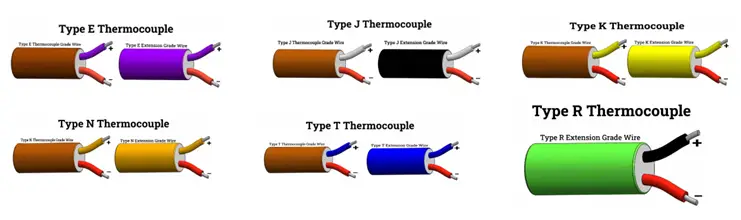
There are several types of thermocouples, each with different temperature ranges and characteristics. The most common types of thermocouples (Refer to Fig. 1 below) are:
Type K Thermocouple
Type K thermocouple is a type of thermocouple that is commonly used for temperature measurement in a variety of applications. It consists of two wires made of different alloys, chromel (90% nickel and 10% chromium) and alumel (95% nickel, 2% manganese, 2% aluminum, and 1% silicon), that are joined together at one end to form a junction. The junction is typically enclosed in a protective sheath made of metal or ceramic material.
Type K thermocouples have a wide temperature range of approximately -200°C to 1,372°C (-328°F to 2,502°F) and are commonly used in applications such as furnace and oven temperature control, gas turbine exhaust monitoring, and in the automotive industry. They have a sensitivity of approximately 41 µV/°C and are known for their high accuracy and stability over a wide temperature range.
One of the advantages of Type K thermocouples is their low cost and widespread availability, which makes them a popular choice for many industrial and scientific applications. However, they may not be suitable for use in certain extreme environments, such as high-temperature applications above 1,000°C (1,832°F), or in corrosive or high-pressure environments, where other types of thermocouples may be more suitable.
Fig. 1: Types of Thermocouples
Type J Thermocouple
Type J thermocouple is a type of thermocouple that is commonly used for temperature measurement in a variety of applications. It consists of two wires made of different alloys, iron, and constantan (55% copper and 45% nickel), that are joined together at one end to form a junction. The junction is typically enclosed in a protective sheath made of metal or ceramic material.
Type J thermocouples have a temperature range of approximately -210°C to 760°C (-346°F to 1,400°F) and are commonly used in applications such as food processing, industrial heating and cooling, and scientific research. They have a sensitivity of approximately 50 µV/°C and are known for their high accuracy and stability over a wide temperature range.
One of the advantages of Type J thermocouples is their high output voltage, which makes them a popular choice for low-temperature applications such as cryogenics and refrigeration. They are also resistant to oxidation and have a long lifespan, making them a reliable choice for many industrial and scientific applications.
The color coding for Type J thermocouples is white for the positive wire and red for the negative wire. It is important to note that the color coding for thermocouples may vary slightly depending on the country or region, and it is recommended to refer to the manufacturer’s documentation or industry standards to ensure proper identification and use of the thermocouple.
Type T Thermocouple
This thermocouple is suitable for use in low-temperature applications, with a temperature range of -270°C to +400°C. It has good accuracy but is less commonly used than Type K and Type J.
Type T thermocouples have a temperature range of approximately -270°C to 400°C (-454°F to 752°F) and are commonly used in applications such as cryogenics, food processing, and pharmaceutical industries. They have a sensitivity of approximately 43 µV/°C and are known for their high accuracy and stability over a wide temperature range.
One of the advantages of Type T thermocouples is their high stability and low drift, making them a popular choice for high-precision temperature measurements. They are also relatively immune to the effects of thermal shock, vibration, and corrosion, making them a reliable choice for many industrial and scientific applications.
The color coding for Type T thermocouples is blue for the positive wire and red for the negative wire. It is important to note that the color coding for thermocouples may vary slightly depending on the country or region, and it is recommended to refer to the manufacturer’s documentation or industry standards to ensure proper identification and use of the thermocouple.
Type E Thermocouple
Type E thermocouple is a type of thermocouple that is commonly used for temperature measurement in a variety of applications. It consists of two wires made of different alloys, chromel (90% nickel and 10% chromium) and constantan (55% copper and 45% nickel), that are joined together at one end to form a junction. The junction is typically enclosed in a protective sheath made of metal or ceramic material.
Type E thermocouples have a temperature range of approximately -270°C to 1,000°C (-454°F to 1,832°F) and are commonly used in applications such as food processing, scientific research, and environmental monitoring. They have a sensitivity of approximately 68 µV/°C and are known for their high accuracy and stability over a wide temperature range.
One of the advantages of Type E thermocouples is their high accuracy at low temperatures, which makes them a popular choice for low-temperature applications such as cryogenics and refrigeration. They are also resistant to oxidation and have a long lifespan, making them a reliable choice for many industrial and scientific applications.
The color coding for Type E thermocouples is purple for the positive wire and red for the negative wire. It is important to note that the color coding for thermocouples may vary slightly depending on the country or region, and it is recommended to refer to the manufacturer’s documentation or industry standards to ensure proper identification and use of the thermocouple.
Type N Thermocouple
This thermocouple is suitable for use in high-temperature applications. It has good accuracy and is often used in aerospace and nuclear applications. It consists of two wires made of different alloys, Nicrosil (84% nickel, 14.2% chromium, and 1.4% silicon) and Nisil (95% nickel and 5% silicon), that are joined together at one end to form a junction. The junction is typically enclosed in a protective sheath made of metal or ceramic material.
Type N thermocouples have a temperature range of approximately -270°C to 1,300°C (-454°F to 2,372°F) and are commonly used in applications such as furnace temperature monitoring, aerospace, and automotive industries. They have a sensitivity of approximately 39 µV/°C and are known for their high accuracy and stability over a wide temperature range.
One of the advantages of Type N thermocouples is their resistance to oxidation at high temperatures, which makes them a popular choice for high-temperature applications. They are also relatively immune to the effects of thermal shock, vibration, and corrosion, making them a reliable choice for many industrial and scientific applications.
The color coding for Type N thermocouples is orange for the positive wire and red for the negative wire. It is important to note that the color coding for thermocouples may vary slightly depending on the country or region, and it is recommended to refer to the manufacturer’s documentation or industry standards to ensure proper identification and use of the thermocouple.
Type R Thermocouple
It consists of two wires made of different alloys, platinum, and rhodium, that are joined together at one end to form a junction. The junction is typically enclosed in a protective sheath made of metal or ceramic material.
Type R thermocouples have a temperature range of approximately 0°C to 1600°C (32°F to 2912°F) and are commonly used in applications such as furnaces, gas turbine exhaust, and other high-temperature environments. They have a sensitivity of approximately 10 µV/°C and are known for their high accuracy and stability over a wide temperature range.
One of the advantages of Type R thermocouples is their high-temperature stability, which makes them suitable for use in harsh and extreme environments. They also have a high resistance to oxidation at high temperatures, which makes them suitable for use in applications where other thermocouples may fail due to oxidation.
The color coding for Type R thermocouples is black for the positive wire and green for the negative wire. It is important to note that the color coding for thermocouples may vary slightly depending on the country or region, and it is recommended to refer to the manufacturer’s documentation or industry standards to ensure proper identification and use of the thermocouple.
Type S Thermocouple
Type S thermocouple is a type of thermocouple that is similar to Type R thermocouple, but is typically used in even higher-temperature applications. It consists of two wires made of different alloys, platinum, and rhodium, that are joined together at one end to form a junction. The junction is typically enclosed in a protective sheath made of metal or ceramic material.
Type S thermocouples have a temperature range of approximately 0°C to 1600°C (32°F to 2912°F) and are commonly used in applications such as aerospace, furnace control, and power plant boilers. They have a sensitivity of approximately 10 µV/°C and are known for their high accuracy and stability over a wide temperature range.
One of the advantages of Type S thermocouples is their high-temperature stability and accuracy, which makes them suitable for use in harsh and extreme environments. They also have a high resistance to oxidation at high temperatures, which makes them suitable for use in applications where other thermocouples may fail due to oxidation.
The color coding for Type S thermocouples is black for the positive wire and orange for the negative wire. It is important to note that the color coding for thermocouples may vary slightly depending on the country or region, and it is recommended to refer to the manufacturer’s documentation or industry standards to ensure proper identification and use of the thermocouple.
Type B Thermocouple
Type B thermocouple is a type of thermocouple that is composed of two different alloys, platinum-rhodium, and platinum-rhodium (30% Rh-6% Rh and 94% Pt-6% Rh), which are joined together to form a junction. This type of thermocouple is commonly used in high-temperature applications, such as in the chemical and petrochemical industries, power plants, and furnaces, where temperatures can exceed 1700°C (3092°F).
Type B thermocouples have a very high-temperature range and are known for their high accuracy and stability at high temperatures. They are also highly resistant to oxidation, which makes them suitable for use in harsh and corrosive environments. However, they are relatively expensive compared to other types of thermocouples, and their sensitivity is lower than other types.
The color coding for Type B thermocouples is white for the positive wire and red for the negative wire. It is important to note that the color coding for thermocouples may vary slightly depending on the country or region, and it is recommended to refer to the manufacturer’s documentation or industry standards to ensure proper identification and use of the thermocouple.
Type C Thermocouple
“Type C” refers to a tungsten-rhenium thermocouple. This type of thermocouple is not commonly used in industrial or commercial applications but is sometimes used in high-temperature research and in laboratory equipment.
Tungsten-rhenium thermocouples have a temperature range of approximately 0°C to 2,300°C (32°F to 4,172°F) and are known for their high accuracy and stability at high temperatures. They are often used in applications such as materials testing, vacuum furnace temperature measurement, and high-temperature research.
The wires of a tungsten-rhenium thermocouple are usually made of tungsten-rhenium alloy and are joined at the measurement junction. The thermocouple wires are often encased in a ceramic or metal sheath for protection. It is important to note that tungsten-rhenium thermocouples are not interchangeable with other types of thermocouples and require special handling and calibration procedures.
Overall, the selection of the appropriate thermocouple type for a particular application depends on several factors, including temperature range, accuracy, and cost.
Color Coding of Thermocouples
Color coding is a standardized method of identifying and distinguishing different types of thermocouples based on the color of the wires used in their construction. The color coding system varies depending on the type of thermocouple but typically consists of a pair of wires, one of which is positive and the other negative. The colors of the wires are used to identify the type of thermocouple, as well as to indicate which wire is positive and which is negative.
Here is a summary of the color coding for some of the most common types of thermocouples:
Type K: Positive wire: Yellow Negative wire: Red
Type J: Positive wire: White Negative wire: Red
Type T: Positive wire: Blue Negative wire: Red
Type E: Positive wire: Purple Negative wire: Red
Type R: Positive wire: Orange Negative wire: Green
Type S: Positive wire: Orange Negative wire: Red
Type B: Positive wire: Red Negative wire: Blue
It is important to note that the color coding for thermocouples may vary slightly depending on the country or region. It is also recommended to refer to the manufacturer’s documentation or industry standards to ensure proper identification and use of the thermocouple.
Uses of Thermocouples in the Oil and Gas Industry
Thermocouples have several important applications in the oil and gas industry, including:
Temperature monitoring in refineries: Thermocouples are used to monitor the temperature of various processes in refineries, such as distillation, cracking, and hydrotreating. Accurate temperature measurement is important for optimizing process efficiency and ensuring product quality.
Downhole temperature measurement: Thermocouples are used in oil and gas wells to monitor the downhole temperature. This information can be used to optimize production and improve recovery rates.
Gas turbine exhaust temperature monitoring: Thermocouples are used to monitor the exhaust temperature of gas turbines used in oil and gas production. Accurate temperature measurement is important for optimizing turbine efficiency and reducing emissions.
Oil and gas pipeline temperature monitoring: Thermocouples are used to monitor the temperature of oil and gas pipelines to ensure that the product is flowing within safe temperature limits. This is important for maintaining pipeline integrity and preventing accidents.
Flare stack temperature monitoring: Thermocouples are used to monitor the temperature of flare stacks used in oil and gas production. Accurate temperature measurement is important for ensuring safe operation and compliance with environmental regulations.
Overall, thermocouples are critical for accurate temperature measurement in various processes and equipment used in the oil and gas industry.
Design Codes and Standards for Thermocouples
There are several design codes and standards that govern the use and design of thermocouples. Some of the most commonly used standards are:
ASTM E230-03: This standard specifies the tolerances for thermocouple wires, which are used to manufacture thermocouples.
ASTM E1129: This standard provides guidelines for the calibration of thermocouples, including methods for determining the temperature-emf relationship and the uncertainty associated with the calibration process.
ANSI/ISA-51.1: This standard provides guidelines for the selection, installation, and use of thermocouples in industrial applications.
IEC 60584: This standard provides guidelines for the selection, installation, and use of thermocouples in a variety of applications.
ASME PTC 19.3 TW: This standard provides guidelines for the use of thermocouples in power plant applications, including design, installation, and calibration.
NIST SP 250-23: This standard provides guidelines for the calibration of thermocouples using fixed-point cells and interpolation techniques.
Overall, the design codes and standards for thermocouples provide guidelines for the selection, installation, calibration, and use of these devices in a variety of industrial and scientific applications. Adhering to these standards helps ensure that thermocouples are accurate, reliable, and safe to use.
Thermocouple Failures
There are several factors that can cause a thermocouple to fail, including:
Oxidation and corrosion: The thermocouple wires are usually made of different metals, which can corrode or oxidize over time, especially in harsh environments. This can cause a reduction in the thermocouple’s output voltage, leading to inaccurate temperature readings.
Contamination: If the thermocouple junction or wires are contaminated with foreign materials, such as dirt or oil, this can affect the accuracy of the temperature reading.
Mechanical stress: If the thermocouple wires or junction are subjected to excessive mechanical stress, such as bending or twisting, this can cause the wires to break or the junction to shift, leading to inaccurate temperature readings.
High temperatures: If the thermocouple is exposed to temperatures higher than its maximum operating range, this can cause the wires to melt or the insulation to break down, leading to failure.
Aging: Over time, the thermocouple wires can age and become more brittle, which can cause them to break or degrade, leading to a loss in accuracy.
Electrical interference: If the thermocouple wires are exposed to electrical interference, such as from nearby power lines or equipment, this can cause interference in the thermocouple’s output signal, leading to inaccurate temperature readings.
Overall, proper installation, use, and maintenance of the thermocouple can help to minimize these failure factors and extend the lifespan and accuracy of the device.
How to Read a Thermocouple?
To read a thermocouple, you will need a thermocouple meter or a device that is capable of measuring the small voltage produced by the thermocouple. Here are the steps to read a thermocouple:
Turn on the thermocouple meter or device and allow it to warm up for a few minutes before taking measurements.
Connect the thermocouple to the meter or device according to the manufacturer’s instructions. The positive and negative wires must be connected correctly, or the readings may be inaccurate.
Insert the thermocouple probe into the material or environment that you want to measure the temperature of. Make sure that the probe is in good contact with the surface of the material or environment.
Wait for a few seconds to allow the thermocouple to stabilize and take a reading from the meter or device. The reading will display the temperature in the units of your choice, such as Celsius or Fahrenheit.
Record the reading and repeat the process as necessary to obtain multiple readings or to monitor changes in temperature over time.
It is important to note that thermocouples may require calibration periodically to ensure accurate readings. Calibration should be performed by a qualified technician or calibration laboratory. Additionally, it is important to follow safety precautions when using thermocouples, especially in high-temperature environments, to avoid injury or damage to equipment.
What is the meaning of the Thermocouple Reference Table?
A thermocouple reference table is a chart or table that provides a list of the temperature-to-voltage conversion values for a specific type of thermocouple at different temperatures. The reference table is based on the thermoelectric properties of the two metals used in the thermocouple, which produce a voltage that is proportional to the temperature difference between the hot junction and the cold junction.
The reference table is essential for accurately measuring temperatures using a thermocouple because it allows the user to convert the voltage output of the thermocouple into a temperature reading. The table typically includes the voltage output for the thermocouple at various temperatures, along with the corresponding temperature values in Celsius or Fahrenheit.
Different types of thermocouples have different reference tables, as the voltage output of each type of thermocouple varies based on the specific metals used in its construction. It is important to use the correct reference table for the specific type of thermocouple being used to ensure accurate temperature measurements. Fig. 2 provides a typical thermocouple reference table for type-k thermocouples.
Fig. 2: Typical Thermocouple Reference Table
Thermocouple for Water Heater
Type J thermocouples are commonly used for water heaters. This is because Type J thermocouples have a relatively low-temperature range and can measure temperatures up to around 750°C (1382°F), which is sufficient for most water heater applications. They also have good accuracy and stability at low temperatures, which is important for measuring the temperature of the water.
In addition, Type J thermocouples are inexpensive, widely available, and easy to replace if necessary, making them a popular choice for water heater manufacturers and maintenance professionals.
It is important to note that other types of thermocouples, such as Type K or Type T, may also be used for water heater applications depending on the specific requirements of the application. It is always recommended to consult the manufacturer’s documentation or industry standards to ensure proper selection and use of the thermocouple for a specific application.
A pipe fabrication shop is a manufacturing facility that specializes in the fabrication of various types of pipes for use in industrial, commercial, and residential applications. These shops typically have a team of skilled fabricators who use various tools and equipment to cut, bend, weld, and shape pipes to specific dimensions and configurations.
Pipe fabrication shops may work with a variety of materials, including steel, stainless steel, aluminum, copper, and other alloys. They may also work with pipes of various sizes and thicknesses, depending on the requirements of the project.
The types of products produced by a pipe fabrication shop can include pipe fittings, flanges, valves, and other components used in piping systems. These products are typically used in industries such as oil and gas, petrochemical, power generation, and water treatment.
Pipe fabrication shops play an important role in the construction and maintenance of various types of infrastructure, and their products are critical components of many industrial processes.
Location of Pipe Fabrication Shop
Pipe fabrication shops can be located in various places depending on the needs of the industry and the clients they serve. They can be found in urban or suburban areas close to industrial parks, ports, or other transportation hubs for easy shipment of the finished products.
Pipe fabrication shops may also be located close to the end-users, such as in oil and gas fields, power plants, or refineries, to facilitate the timely delivery of products and services.
In some cases, pipe fabrication shops are also mobile and can be brought to the job site for on-site fabrication and installation. This approach is often used for large-scale construction projects where the pipes need to be installed quickly and efficiently.
Overall, the location of a pipe fabrication shop will depend on the needs of the industry it serves and the services it provides.
Importance of Pipe Fabrication Shops
Pipe fabrication shops play a critical role in piping construction for the oil and gas industries. They are responsible for producing the necessary components for piping systems, including pipes, fittings, and valves. Here are some of the specific roles that pipe fabrication shops play:
Fabrication of pipes: Pipe fabrication shops are responsible for fabricating pipes of various materials, sizes, and thicknesses. They use specialized equipment, such as pipe-cutting and bending machines, to produce the required pipe sections.
Fabrication of fittings: Pipe fabrication shops also produce pipe fittings, such as elbows, tees, reducers, and flanges. These components are necessary for connecting pipe sections and ensuring that the piping system is properly sealed.
Welding: Pipe fabrication shops employ skilled welders who are responsible for welding the pipes and fittings together. Welding is a critical process that ensures the structural integrity and safety of the piping system.
Quality control: Pipe fabrication shops have quality control processes in place to ensure that the finished products meet the required standards and specifications. This includes testing the welds and performing non-destructive testing to identify any defects.
On-time delivery: Pipe fabrication shops work closely with contractors and construction firms to ensure that the required components are delivered on time. This is critical for the timely completion of construction projects and for minimizing downtime in the oil and gas industry.
Overall, pipe fabrication shops are an essential part of the piping construction process for the oil and gas industries. They provide the necessary components and services to ensure that piping systems are safe, reliable, and meet the required specifications.
Common Fabrication Processes in a Pipe Fabrication Shop
A pipe fabrication shop performs several processes to fabricate pipes and other components used in various industrial, commercial, and residential applications. Here are some of the common processes performed inside a pipe fabrication shop:
Cutting: The first step in pipe fabrication is cutting the pipes to the required lengths. Pipe fabrication shops use various cutting tools, such as band saws, abrasive saws, and plasma cutters, to cut pipes of different sizes and thicknesses.
Bending: Once the pipes are cut to length, they may need to be bent to specific angles and radii. Pipe fabrication shops use specialized bending machines to bend pipes accurately and uniformly.
Welding: Welding is a critical process in pipe fabrication. Skilled welders use various welding techniques, such as stick welding, TIG welding, and MIG welding, to join pipes and fittings together.
Fitting assembly: After the pipes are cut, bent, and welded, they need to be assembled with fittings, flanges, and valves. Pipe fabrication shops use specialized assembly fixtures to ensure that the fittings are properly aligned and secured.
Surface preparation: Surface preparation is an essential step in pipe fabrication, particularly for pipes that will be used in corrosive environments. Pipe fabrication shops may use techniques such as sandblasting or chemical cleaning to remove rust, scale, and other contaminants from the pipes.
Quality control: Pipe fabrication shops have quality control processes in place to ensure that the finished products meet the required standards and specifications. This includes testing the welds and performing non-destructive testing to identify any defects.
Overall, pipe fabrication shops use a combination of cutting, bending, welding, fitting assembly, surface preparation, and quality control processes to fabricate pipes and other components used in various applications.
Shop Fabrication vs Site Fabrication
Shop fabrication and site fabrication are two methods used in the construction of piping systems. Here are the differences between the two:
Location: Shop fabrication takes place in a controlled environment, typically in a dedicated fabrication facility, while site fabrication takes place on the job site where the piping system is being installed.
Process: Shop fabrication involves pre-fabricating components such as pipes, fittings, and spools in the fabrication facility before transporting them to the job site. Site fabrication, on the other hand, involves fabricating components on the job site itself.
Quality Control: Shop fabrication offers better quality control as the fabrication process is carried out in a controlled environment, under strict quality control procedures. Site fabrication, on the other hand, may be subject to varying environmental conditions that can impact the quality of the work.
Cost: Shop fabrication is typically more expensive than site fabrication as it involves the use of specialized equipment and skilled labor. Site fabrication, on the other hand, maybe less expensive as it can be carried out using less specialized equipment and less skilled labor.
Logistics: Shop fabrication allows for better planning and coordination of the construction process as components are fabricated off-site and transported to the job site as required. Site fabrication, on the other hand, may be subject to delays due to weather or other factors that can impact the ability to carry out the work.
Overall, both shop fabrication and site fabrication have their advantages and disadvantages. The decision to use one method over the other depends on the specific requirements of the project and the available resources.
The decision to shop fabricate or site fabricate components of a piping system depends on various factors such as project requirements, cost, schedule, and logistics. Here are some common components that are shop-fabricated and site fabricated in the piping construction process:
Shop Fabricated:
Pipes: Pipes are typically shop fabricated to the required lengths, with the necessary bends and fittings welded in place before they are transported to the job site.
Pipe fittings: Pipe fittings, such as elbows, tees, reducers, and flanges, are usually fabricated in the shop to ensure that they are properly aligned and welded together.
Spools: Spools are pre-fabricated assemblies of pipes and fittings that are joined together in the shop and transported to the job site.
Pipe supports: Pipe supports, such as hangers and clamps, are typically shop fabricated to the required specifications.
Site Fabricated:
Field joints: Field joints are the connections made between the pipes on the job site, and are typically site fabricated using welding or mechanical jointing techniques.
Field fittings: In some cases, fittings may need to be fabricated on the job site to accommodate specific field conditions.
Tie-ins: Tie-ins are connections between the piping system and other components of the facility, such as equipment or other piping systems. Tie-ins are typically site fabricated to ensure proper alignment and fit.
Repairs and modifications: Repairs and modifications to the piping system may also be site fabricated to ensure that they are properly integrated into the existing system.
Overall, the decision to shop fabricate or site fabricate components of a piping system depends on the specific requirements of the project and the logistics involved in transporting and installing the components.